Gira KNX 5062 00 Manuale utente


Switching actuator 2-gang / blind actuator, 1-gang 16 A with binary input, 3-gang
Table of Contents
1 Safety instructions.............................................................................................................3
2 Device components...........................................................................................................4
3 Function ............................................................................................................................5
4 Information for electrically skilled persons ........................................................................7
4.1 Mounting and electrical connection........................................................................ 7
4.2 Commissioning ...................................................................................................... 9
5 Technical data.................................................................................................................11
6 Accessories.....................................................................................................................13
7 Warranty..........................................................................................................................13
2 / 13
82404232 29.11.2022

1 Safety instructions
Electrical devices may only be mounted and connected by electrically skilled
persons.
Serious injuries, fire or property damage possible. Please read and follow manual
fully.
Danger of electric shock. Device is not suitable for disconnection from supply
voltage.
Danger of electric shock. Make sure during the installation that there is always suffi-
cient insulation between the mains voltage and the bus. A minimum distance of at
least 4 mm must be maintained between bus conductors and mains voltage cores.
Danger of electric shock on the KNX installation. Do not connect any external voltage
to the inputs. The device might be damaged, and the SELV potential on the KNX bus
line will no longer be available.
For parallel connection of several motors to an output it is essential to observe the
corresponding instructions of the manufacturers, and to use a cut-off relay if neces-
sary. The motors may be destroyed.
Use only Venetian blind motors with mechanical or electronic limit switches. Check
the limit switches for correct adjustment. Observe the specifications of the motor
manufacturers. Device can be damaged.
This manual is an integral part of the product, and must remain with the end cus-
tomer.
3 / 13
82404232 29.11.2022
Switching actuator 2-gang / blind actuator, 1-gang 16 A with binary input, 3-gang

2 Device components
Image1: Device components
(1) Programming LED
(2) Programming button
(3) Control cable (KNX connection and extension inputs)
(4) Connection of load (relay outputs)
Image2: Connection assignment of control cable (example)
red (RD) KNX +
black (BK) KNX -
green (GN) Input 1 (push-button, switch, contact, condensation/leakage sensor)
yellow (YE) Input 2 (push-button, switch, contact, condensation/leakage sensor)
white (WH) Input 3 (push-button, switch, contact, condensation/leakage sensor,
NTC temperature sensor)
brown (BN) COM inputs 1...3
4 / 13
82404232 29.11.2022
Switching actuator 2-gang / blind actuator, 1-gang 16 A with binary input, 3-gang

3 Function
System information
This device is a product of the KNX system and complies with the KNX directives.
Detailed technical knowledge obtained in KNX training courses is a prerequisite to
proper understanding.
The function of this device depends upon the software. Detailed information on load-
able software and attainable functionality as well as the software itself can be ob-
tained from the manufacturer´s product database.
The device can be updated. Firmware can be easily updated with the Gira ETS Ser-
vice App (additional software).
The device is KNX Data Secure capable. KNX Data Secure offers protection against
manipulation in building automation and can be configured in the ETS project. De-
tailed specialist knowledge is required. A device certificate, which is attached to the
device, is required for safe commissioning. During mounting, the device certificate
must be removed from the device and stored securely.
Planning, installation and commissioning of the device are carried out with the aid of
the ETS, version 5.7.3 and above.
Intended use
– Operating in KNX systems
– Switching electrical loads via relay contacts with common reference potential
– Switching of electrically-driven Venetian blinds, roller shutters, awnings and
similar hangings
– Reading in switching states of installation switches or push-buttons and other
potential-free contacts at inputs 1...3
– Signal evaluation of condensation and leakage sensors at inputs 1...3 (see ac-
cessory).
– Acquisition of temperature values via NTC temperature sensor at input 3 (see
accessories)
– Mounting in appliance boxes according to DIN 49073
Product characteristics
– Outputs can be operated via KNX telegrams or extension inputs
– Three extension inputs for connecting potential-free contacts or dew/leakage
sensors. NTC temperature sensor can be connected to input 3.
– Supply via KNX, no additional power supply necessary
– KNX Data Secure compatible
– Updatable with Gira ETS Service App
5 / 13
82404232 29.11.2022
Switching actuator 2-gang / blind actuator, 1-gang 16 A with binary input, 3-gang

Characteristics switch operation
– Operation as NO or NC contacts
– Feedback function
– Logic and restraint function
– Central switching functions with collective feedback
– Time functions: switch-on delay, switch-off delay, staircase lighting timer with
run-on time
– Scene function
– Operating hours counter
Characteristics blinds operation
– Operating modes "Venetian blind with slats", "Roller shutter/awning", "Venting
louvre/roof window"
– Blind/shutter position directly controllable
– Slat position directly controllable
– Feedback of movement status, blind/shutter position and slat position
– Forced position through higher-level controller
– Safety function: 3 independent wind alarms, rain alarm, frost alarm
– Sun protection function with heating/cooling operation
– Disabling function (lock-out protection)
– Scene function
Extension input characteristics
– Switching operating function
– Dimming operating function (incl. colour temperature dimming)
– Shutter/Venetian blinds operating function
– Value transmitter operating function (1-byte, 2-byte, 3-byte and 6-byte incl.
RGBW and colour temperature presets)
– Scene extension operating function
– 2-channel operation operating function
– Controller extension operating function
– Disabling functions
– Debounce time adjustable
Logic function characteristics
– Logic gate
– Transformer (conversion)
– Disabling element
– Comparator
6 / 13
82404232 29.11.2022
Switching actuator 2-gang / blind actuator, 1-gang 16 A with binary input, 3-gang

– Limit value switch
4 Information for electrically skilled persons
DANGER!
Mortal danger of electric shock.
Disconnect the device. Cover up live parts.
4.1 Mounting and electrical connection
DANGER!
When connecting the bus/extensions and mains voltage wires in a shared appliance
box, the KNX bus line may come into contact with the mains voltage.
This endangers the safety of the entire KNX installation. People at remote devices
may also receive an electric shock.
Do not place bus/extensions and mains voltage terminals in a shared connection
compartment. Use an appliance box with a fixed partition wall or separate appliance
boxes.
Connecting and fitting the device
In secure operation (preconditions):
– Secure commissioning is activated in the ETS.
– Device certificate entered/scanned or added to the ETS project. A high resolu-
tion camera should be used to scan the QR code.
– Document all passwords and keep them safe.
Mounting in suitable appliance box (recommendation: electronic device box with par-
tition). Observe cable routing and spacing (see figure 3)!
7 / 13
82404232 29.11.2022
Switching actuator 2-gang / blind actuator, 1-gang 16 A with binary input, 3-gang

Image3: Mounting example in electronic appliance box with partition wall, series
push-button and NTC temperature sensor
(5) Appliance box
(6) Partition
(7) potential-free contacts (e.g. series push-button)
(8) NTC temperature sensor (optional)
Image4: Cable spacing
Minimum spacing between the mains voltage and bus/extension wires: 4 mm
(see figure 4)
8 / 13
82404232 29.11.2022
Switching actuator 2-gang / blind actuator, 1-gang 16 A with binary input, 3-gang

Image5: Connection of load
Observe ambient temperature. Ensure adequate cooling.
■ Connect bus line, observing the correct polarity.
■ Connect load as shown in the connection example (see figure 5).
■ If required, connect potential-free contacts or condensation/leakage sensors to
inputs 1...3, or NTC temperature sensors to input 3 (see figure 2).
■ Install the device in the appliance box.
■ In secure operation: The device certificate must be removed from the device
and stored securely.
The COM reference potential must not be connected together with COM con-
nections of other devices!
4.2 Commissioning
Commissioning the device
NOTICE!
Incorrect load control due to undefined relay state at delivery.
Risk of destruction of connected drive motors.
During commissioning, before switching on the load, ensure that all relay contacts
are open by applying the KNX bus voltage. Observe commissioning sequence!
9 / 13
82404232 29.11.2022
Switching actuator 2-gang / blind actuator, 1-gang 16 A with binary input, 3-gang
■ Switch on the KNX bus voltage.
■ Wait about 10 s.
■ Connect the load circuit.
Delivery state: The output is set as a Venetian blind output. Operation of the
blind output possible via input 1 (UP) and input 2 (DOWN). Input 3 has no
function.
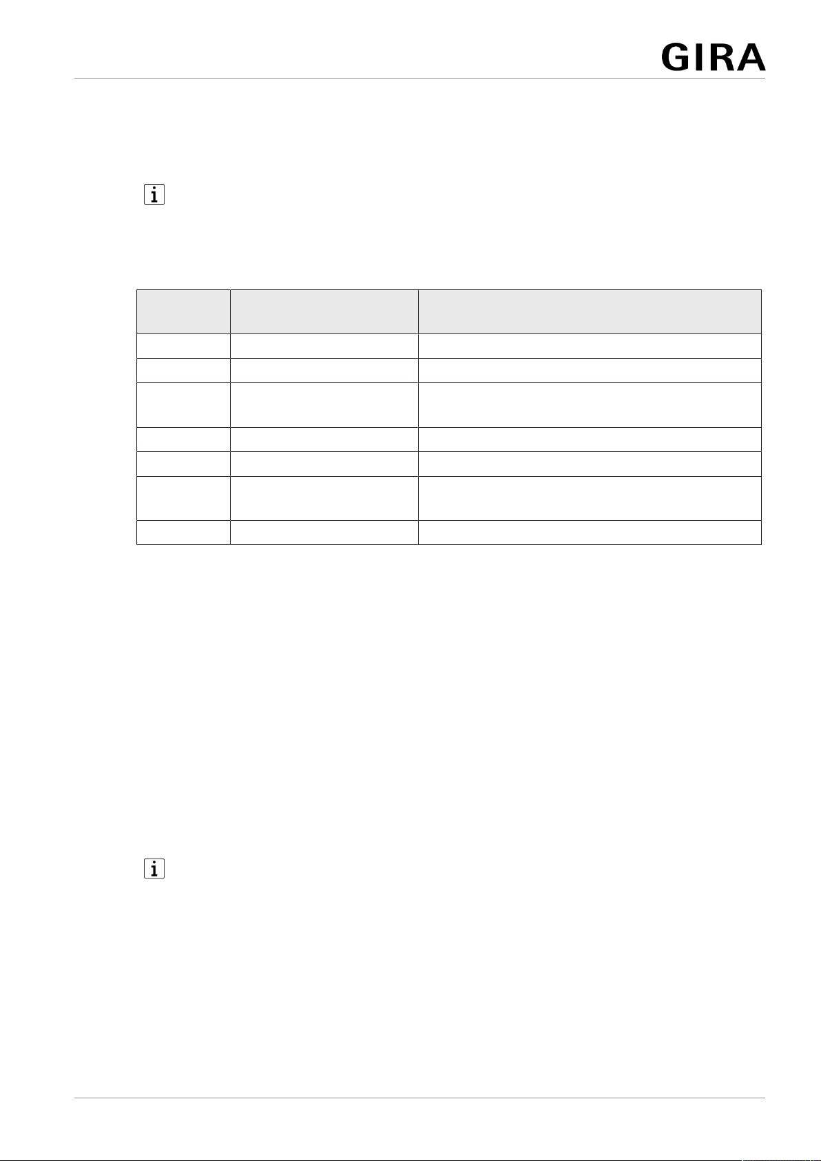
Function of Inputs in the as-delivered state
Input Push-button (NO con-
tact)
Function
1 Press briefly (< 0.4 s) Stop
1 Press briefly (< 0.9 s) Adjusting the slats UP
1 Press for a long time (>
0.9 s)
Raise
2 Press briefly (< 0.4 s) Stop
2 Press briefly (< 0.9 s) Adjusting the slats DOWN
2 Press for a long time (>
0.9 s)
Lower
3 --- ---
Load physical address and application program
■ For switched loads, configure the outputs as a switching output.
■ For Venetian blind operation, configure the outputs as a Venetian blind output.
■ In Venetian blind operation: measure blind/shutter and slat travel times and
enter them in the parameter setting.
■ Press the programming button.
The programming LED lights up.
■ Load physical address and application program using the ETS.
Safe-state mode
The safe-state mode stops the execution of the loaded application program.
Only the system software of the device is still functional. ETS diagnosis func-
tions and programming of the device are possible.
Activating safe-state mode
■ Switch off the bus voltage or disconnect the device from the KNX.
■ Wait about 10 s.
■ Press and hold down the programming button.
■ Switch on the bus voltage or connect the device to KNX. Release the pro-
gramming button only after the programming LED starts flashing slowly.
10 / 13
82404232 29.11.2022
Switching actuator 2-gang / blind actuator, 1-gang 16 A with binary input, 3-gang
Indice
Altri manuali Gira Controllori

Gira
Gira 0399 00 Manuale utente

Gira
Gira 5423 00 Manuale utente

Gira
Gira 0570 00 Manuale utente

Gira
Gira Powernet Switchactuator 2fold Manuale utente

Gira
Gira One 5062 00 Manuale utente

Gira
Gira 1289 00 Manuale utente

Gira
Gira 2101 Series Manuale utente

Gira
Gira KNX 1039 00 Manuale utente

Gira
Gira One Manuale utente

Gira
Gira One 5061 00 Manuale utente

Gira
Gira 5431 00 Manuale utente

Gira
Gira System 3000 Manuale utente

Gira
Gira 2100 Series Manuale utente

Gira
Gira 1288 Series Manuale utente

Gira
Gira G1 Manuale utente

Gira
Gira 5023 00 Manuale utente

Gira
Gira KNX 213900 Manuale utente

Gira
Gira 0566 Series Manuale utente

Gira
Gira Powernet Single Switching Actuator Manuale utente

Gira
Gira 2164 00 Manuale utente


