
Gree GMV5 Series Manuale utente
Gree Intelligent Remote System
Service Manual

Safety Notices
Dear users:
Before installation and operation, please read this manual carefully, and install and operate
the unit according to the procedures specified in the instruction manual. Please pay attention to the
meaning of the marks as below:
Warning
This sign indicates that improper operation may cause damage death to people or severe
damage.
Notice
This sign indicates that improper operation may cause damage to the unit.
Warning
1. Be sure to ask professional person to install the unit. Improper installation may result in fire
or electric shock.
2. Confirm the power plug is dry after cleaning before inserting it into the socket.
3. Before touch the electrical components, please make sure that the unit is disconnected with
the power.
4. Do not touch this unit with wet hands; otherwise, it may cause electric shock.
5. Be sure to use the power cord with specified specifications. Poor contact or improper
installation may result in a fire.
6. Power cord is connected reversely or input power is beyond the allowable range, it may lead
to fire, and cause damage to the device.
7. Please be sure to install this unit at the indoor locked electrical control cabinet which is
difficult to reach.
8. Please install the unit at the place where is not affected by electromagnetic interference or
there’s no dust.
Notice
1. Please make sure the specification of the power adapter; otherwise, the unit will not work
properly or even be damaged.
2. Make sure that the device is assembled at the right place; otherwise it will cause

communication failures.
3. Make sure that the communication lines are connected to the correct interface; otherwise it
will cause communication failures.
4. Once wires are connected, protect them with insulating tapes to prevent lest oxidation and
short circuit.
5. The normal working environmental requirements of the Controller:
(1)temperature: - 20 ~ + 60 ℃.
(2)the humidity is less than or equal to 85% ,except frosting.
(3)installed in indoor electrical control cabinet, avoid direct sunlight, rain, snow and so on.

Content
1 Summary..............................................................................................................................1
1.1 Components....................................................................................................................1
1.2 Network Topological Diagram.........................................................................................1
2 Details of Gree Intelligent Remote System.......................................................................1
2.1 Controller ........................................................................................................................3
2.2 Router.............................................................................................................................7
2.3 Intelligent Remote Eudemon...........................................................................................7
3 Product Installation.............................................................................................................8
3.1 Controller Dimensions and Installation Dimensions for Electric Control Cabinet............8
3.2 Installation and Configuration of Router..........................................................................9
3.3 Installation of Intelligent Remote Eudemon ..................................................................10
3.4 Communication Connection..........................................................................................10
3.5 Communication Connection Configuration ...................................................................12
4 Product Debugging Instruction .......................................................................................13
4.1 Debugging of Air Conditioner........................................................................................13
4.2 Debugging of Controller................................................................................................14
4.3 Debugging of Software .................................................................................................17
Appendix A: COMMON TROUBLESHOOTING OF INTELLIGENT REMOTE EUDEMON
SYSTEM.................................................................................................................................18
Appendix B: TCP/IP Setting ................................................................................................19

Gree Gree Intelligent Remote System
1
1 Summary
Intelligent Remote Eudemon System is composed of Intelligent Remote Eudemon and
Intelligent Controller, to realize the intelligent remote Eudemon system to monitor and control VRF.
Through Intelligent Remote Eudemon System, it can conduct data collection, monitor and
control to the operation status of GMV air conditioner in long distance and timely give an alarm
once malfunction occur. The air conditioning maintenance staffs do not need to conduct setting and
management to every unit on site in person, instead, they can check the operation status, start and
operation, and have temperature setting of building air conditioning system by just sitting in front of
the computer, which not only greatly enhances work efficiency, but also decreases human cost and
lower management cost.
Detailed models applicable for this system include: GMV5(3PH), GMV5C(3PH), GMV5
MAX(3PH), GMV5 HR(3PH), GMV5 SLIM(3PH), GMV5 MINI(3PH),GMV6.
1.1 Components
This system shall use the components as shown below. Please check before installation.
Component name Quantity Availability
Intelligent Remote Eudemon 1 set Standard
Router Several Self-equipped
ME20-24/D1(T) Several Standard
1.2 Network Topological Diagram
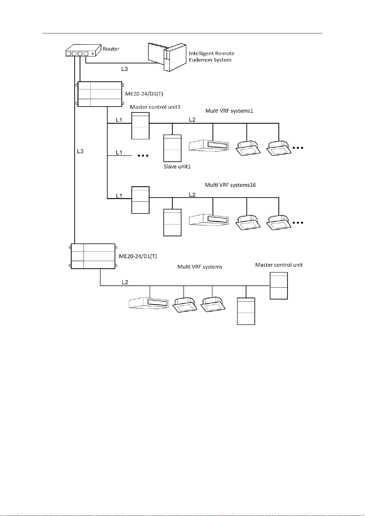
One set of Gree Intelligent Remote System consists of one Intelligent Remote Eudemon
(computer software), 32 controllers in maximum. One controller can be connected to 32 systems
and 255 indoor units in maximum. User can determine the number of controller in a Remote system
according to the number of units in a project.
Network Topological Structure of Gree Intelligent Remote System is as follows:
Instructions of network topological diagram:
Gree Gree Intelligent Remote System
2
Fig. 1.1 Network topology
topological graph statement:
CAN2 bus network: L1 shown in Fig. 1.1 is CAN2 bus, which consists of controller and master
outdoor unit of system; one CAN2 network can connect to 16 sets of outdoor units and 255 sets of
indoor units. When the quantity of outdoor units exceeds 16 or the quantity of indoor units exceeds
255, it should be divided into two CAN2 networks.
CAN1 bus network: L2 shown in Fig. 1.1 is CAN1 bus, which consists of network and all the
outdoor units and indoor units of system; one CAN1 network can connect to 80 sets of indoor units
at most.
Network table: L3 shown in Fig. 1.1 is general network cable, the controller can connect to

Gree Gree Intelligent Remote System
3
Intelligent Remote Eudemon via the network cable.
System: one system consists of one set of outdoor units (one set of outdoor unit is a module
set, can consist 1~4 modules, that is, 1~4 sets of outdoor units) and its indoor units.
Quantity of units can be connected to Intelligent Controller: one Intelligent Controller supports
one CAN2 network, can connect to 16 sets of systems or 255 sets of indoor units.
Note: L3 in Fig. 1.1 is standard netting twine, L1 and L2 are twisted-pairs.
2 Details of Gree Intelligent Remote System
2.1 Controller
2.1.1 Diagram of Ports
Fig. 2.1 Schematic of interfaces
2.1.2 Power Supply
The input power supply is 24V DC, there are two power supply input interfaces, only one is
needed during operation; the power supply output is not applicable in this device, please do not
connect to electric appliance, otherwise it may cause malfunction of Controller.
Gree Gree Intelligent Remote System
4
2.1.3 Communication Port
CAN communication port: Connect to air conditioners via two-core communication cable to
obtain data from air conditioners.
RS485-1 communication port: currently not available for this device.
RS485-2 communication port: currently not available for this device.
USB, DEBUG, MICRO SD card ports: currently not available for this device.
Ethernet port ETH0: Connect via network cable to the computer that is installed with
Intelligent Remote Eudemon.
Ethernet port CONFIG: currently not available for this device.
2.1.4 LED
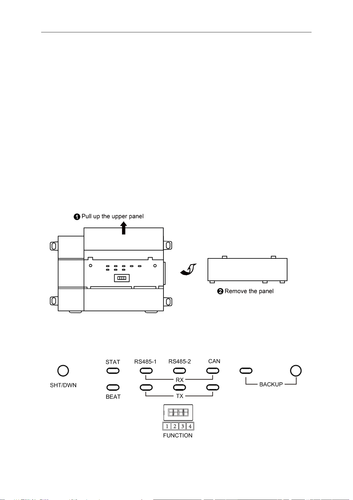
As shown in the picture below, open the black transparent front panel.
Fig 2.2 Schematic diagram of opening the black transparent board
Indicators, buttons and DIP switch are as shown below.
Gree Gree Intelligent Remote System
5
CAN RX When data is received, this LED indicator will be flickering.
TX When data is sent, this LED indicator will be flickering.
RS485-1 RX currently not available for this device.
TX currently not available for this device.
RS485-2 RX This LED display is not applicable to this device.
TX This LED display is not applicable to this device.
STAT If power supply of controller is normal, this indicator will be on.
BEAT If controller is operating normally, this indicator will be flickering.
BACKUP This LED display is not applicable to this device.
2.1.5 Button
SHT/DWN When the fourth digit of DIP switch code is “1”, hold the button for 5s and all
indicators will be on. Reset the Controller controller.
BACKUP Not use this button for this device temporarily.
2.1.6 DIP Switch
※Before using this device, set the DIP switch first. otherwise the device will not work.
Controller DIP switch code setting area is composed of function DIP switch code.
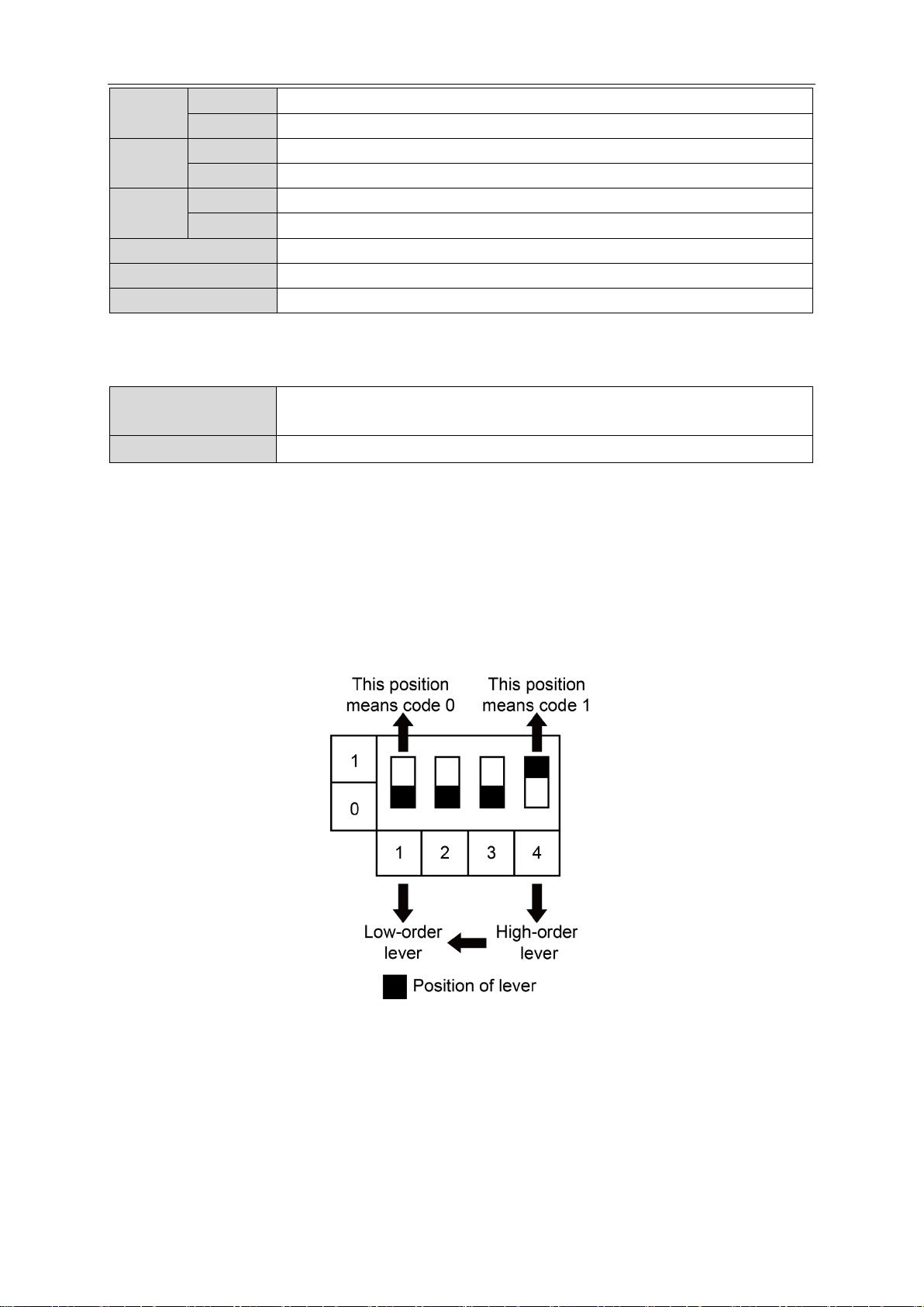
2.1.6.1 Diagram of DIP Switch
2.1.6.2 The 1st Lever of Functional DIP Switch—CAN2 Bus Matched Resistance
Setting
The master outdoor unit or controller at the beginning or ending place of CAN2 bus must be
set with matched resistance. otherwise communication will not work!
※CAN2 bus: please refer to 1.2 Network Topological Diagram for its specific meaning.

Gree Gree Intelligent Remote System
6
The 1st lever of the functional DIP switch is used for setting matched resistance for controller
in CAN2 bus.
If controller is at the beginning / ending place of CAN2 bus, it should be set with matched
resistance, which means the 1st lever should be switched to 1.
If the controller is not at the beginning / ending place of CAN2 bus, it should be set without
matched resistance, which means the 1st lever should be switched to 0.
Fig. 2.3 Controller access CAN2 network matching resistance setting
n refers to the number of outdoor systems, n≤16.
Diagram of Matched Resistance DIP Switch:
Fig. 2.4 Schematic of dial code
2.1.6.3 The 4th Lever of Functional DIP Switch—Controller Reset Selection Bits
When there’s an error in configuring Controller IP address, subnet mask, default Controller,
Altri manuali per GMV5 Series
6
Questo manuale è adatto per i seguenti modelli
7
Indice
Altri manuali Gree Telecomando


