Growatt ARK 2.5H-A1 Manuale utente

ARK High Voltage Battery System
User Manual (V1.0)

2 / 28
About this Document
This document describes the installation, electrical connection, operation, commission, maintenance and troubleshooting of ARK
High Voltage Battery System. Before installing and operating ARK High Voltage Battery System, ensure that you are familiar with
product features, functions, and safety precautions provided in this document.
Symbol Description
Indicates a potentially hazardous situation, if not avoided, could result in
serious injury or death.

3 / 28
Table of Contents
1. Product Overview ................................................................................................................................................. 4
1.1 Intended Use ................................................................................................................................................... 4
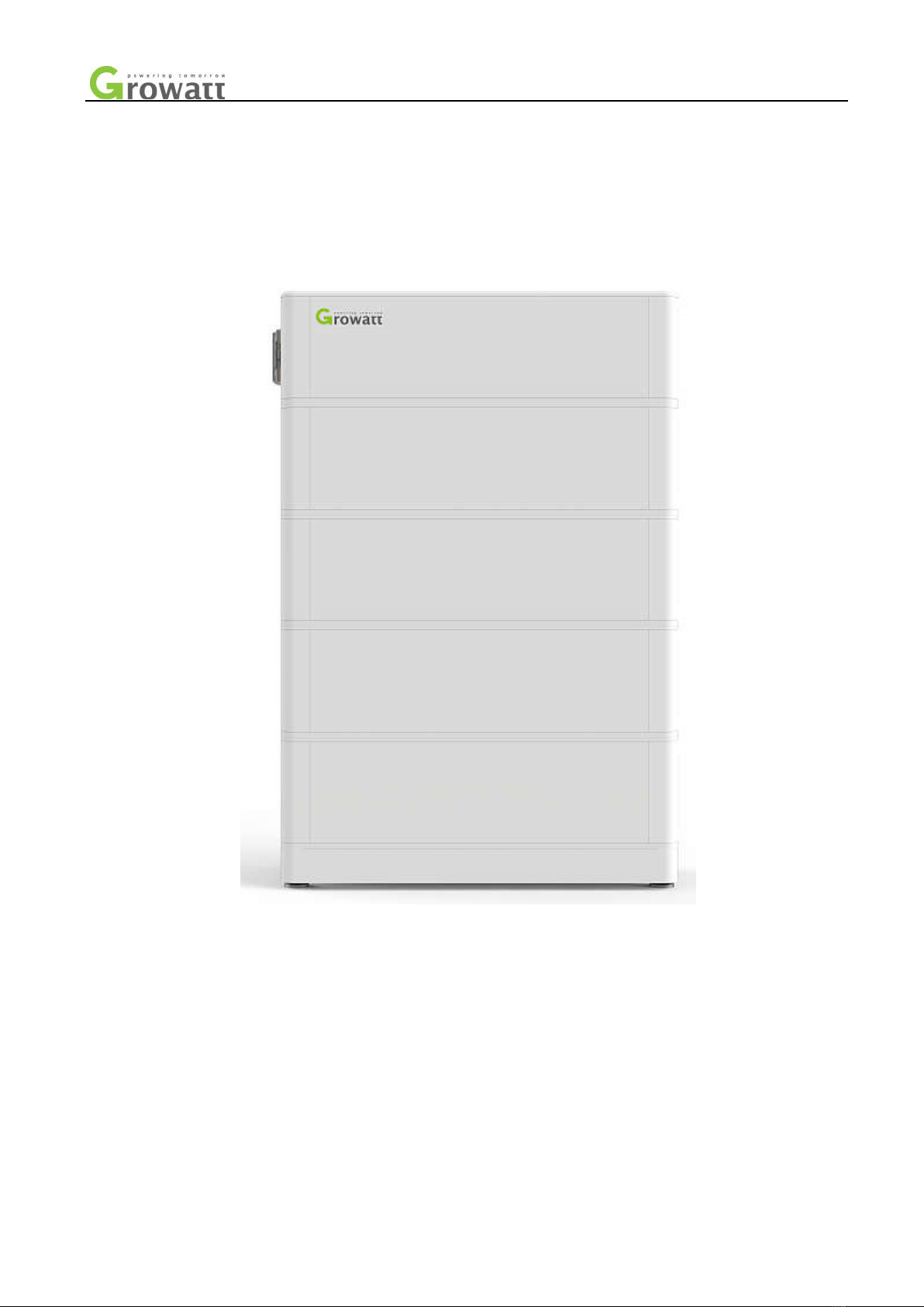
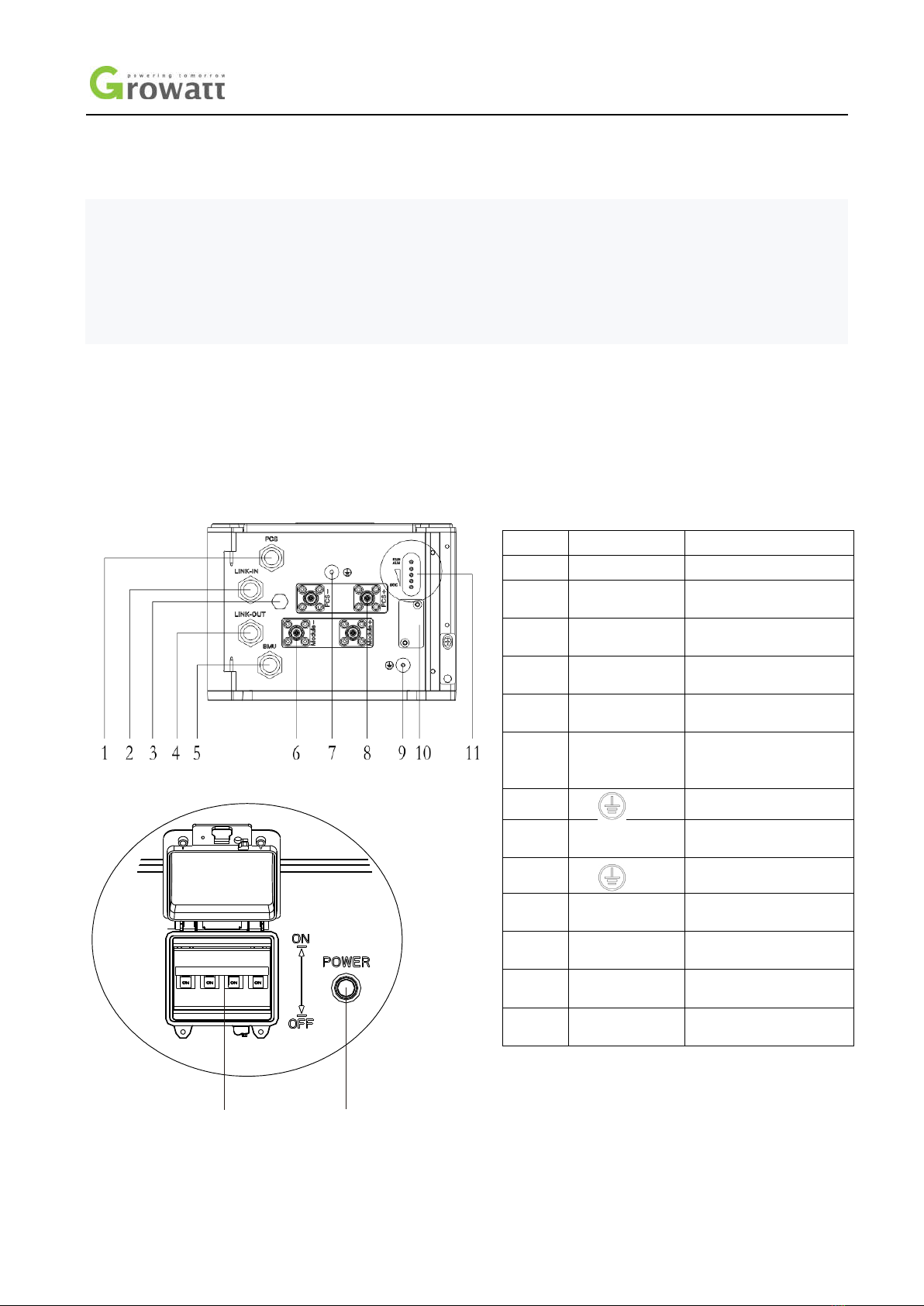
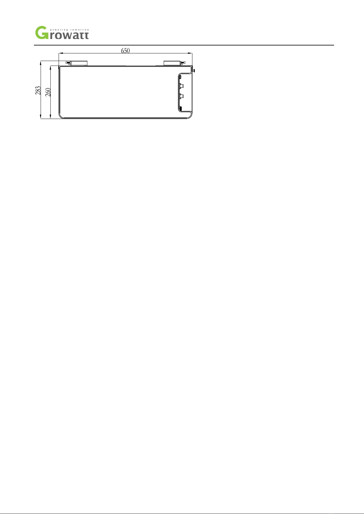
1.2 Appearance ..................................................................................................................................................... 4
1.3 Working Principle and Function ...................................................................................................................... 6
2. Safety .................................................................................................................................................................... 6
2.1 Basic security .................................................................................................................................................. 6
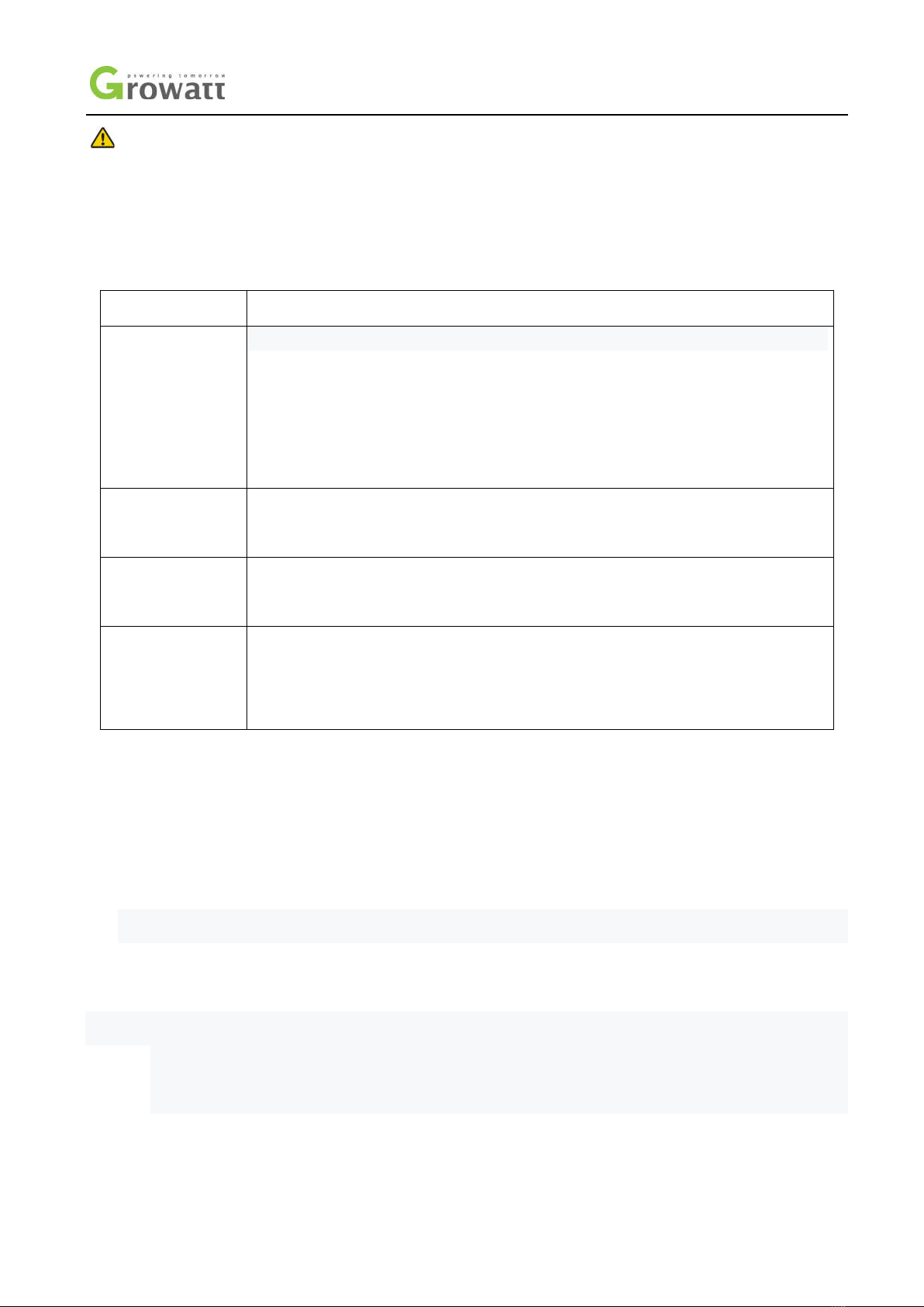
2.2 Safety Precautions .......................................................................................................................................... 7
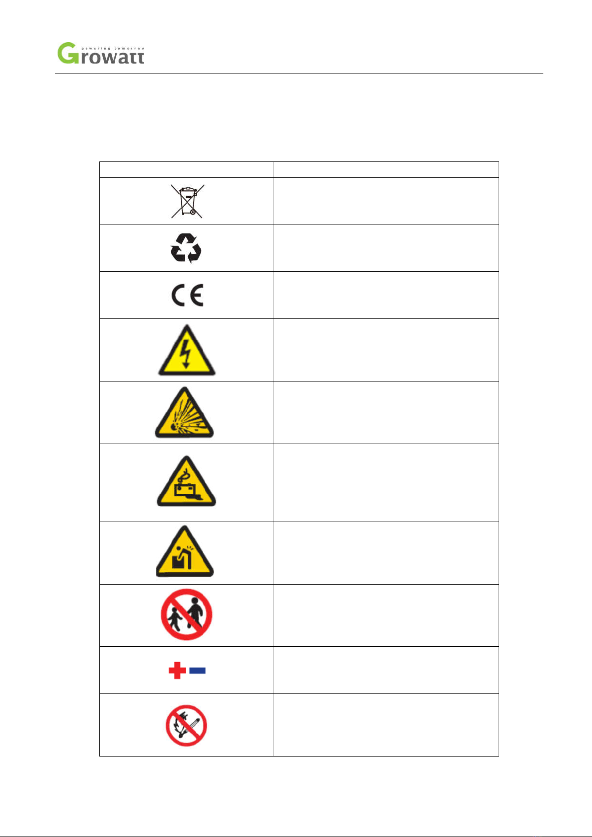
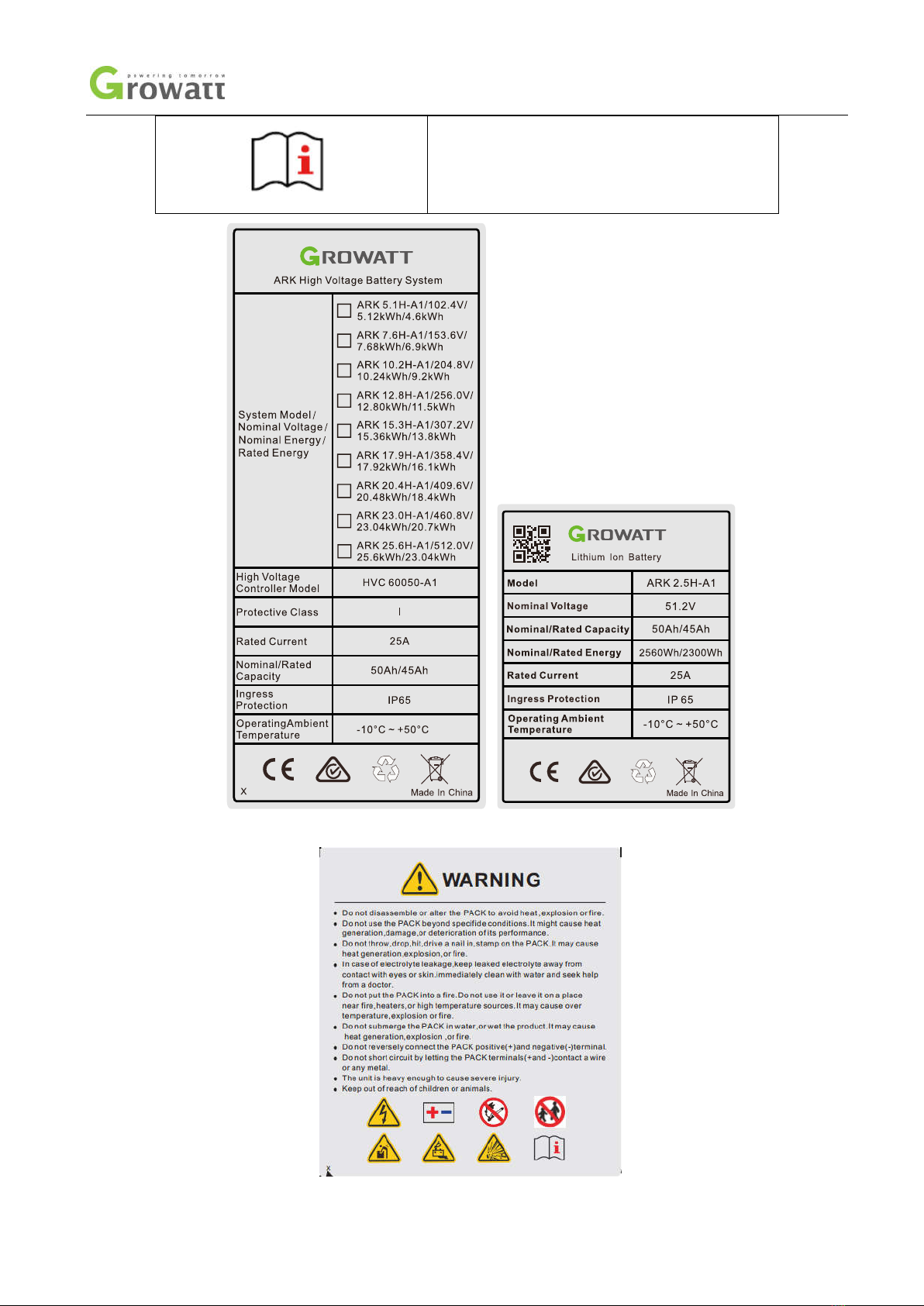
2.3 Warning Labels................................................................................................................................................ 8
2.4 Emergency Responses .................................................................................................................................. 10
3. Storage and Transportation ................................................................................................................................ 10
3.1 Storage Requirements .................................................................................................................................. 10
3.2 Transportation Requirement ......................................................................................................................... 11
4. Installation .......................................................................................................................................................... 11
4.1 Basic Installation Requirements .................................................................................................................... 12
4.2 Installation Required Tools ............................................................................................................................ 13
4.3 Installation Procedures ................................................................................................................................. 14
4.4 Electrical Connection .................................................................................................................................... 17
5. Power on/off Battery system ............................................................................................................................... 20
5.1 Power on Battery system .............................................................................................................................. 21
5.2 Power off battery system .............................................................................................................................. 21
6. Maintenance Guide ............................................................................................................................................. 21
6.1 Preparation ................................................................................................................................................... 21
6.2 Battery pack or high voltage controller replacement ................................................................................... 21
6.3 System fault information and suggestions .................................................................................................... 22
7. Technical Specifications ....................................................................................................................................... 23
7.1 System Data .................................................................................................................................................. 23
7.2 Battery System designation .......................................................................................................................... 24
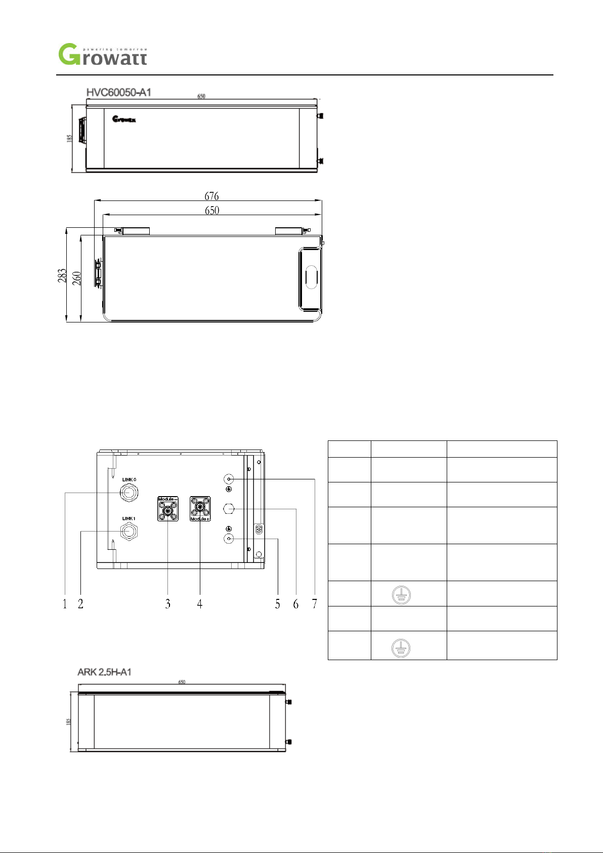
7.3 HVC 60050-A1 ............................................................................................................................................... 25
7.4 ARK 2.5H-A1 .................................................................................................................................................. 25
Appendix I ................................................................................................................................................................... 26
Appendix II .................................................................................................................................................................. 27

4 / 28
1. Product Overview
1.1 Intended Use
The entire ARK High Voltage Battery System includes a HVC 60050-A1(high voltage controller) and multiple ARK 2.5H-A1 (battery
pack).
Each ARK 2.5H-A1 consists of 50Ah cells which form 51.2V voltage battery pack via one parallel and sixteen serial connection
(1P16S). Two to ten ARK 2.5H-A1 can be connected in serial to extend the capacity and power of energy storage system.
The ARK battery system powers the loads through PCS at nighttime without solar; when solar becomes available during daytime,
solar energy powers the loads as a priority and store residual solar power into the ARK battery system.
1.2 Appearance
1.2.1 HVC 60050-A1 (high voltage controller)
The high voltage controller
is composed of battery control unit, DC breaker, power supply and communication terminals. The appearance of the product is sh
own as below.
12 1 3
Figure 2: Schematic diagram of power panel
Dimension (unit: mm)
Location
Port Function
1 PCS Communication with PCS
2 Link-In Battery system parallel
communication entrance
3 Pressure relief
valve
Pressures inside is
released via the vent
4 Link-Out Battery system parallel
communication export
5 BMU Communication with
battery module
6 Module+/
Module-
Connect to the power
terminal of the battery
string
7 Ground terminal
8 PCS+/PCS- The output from battery
system to the PCS
9 Ground terminal
10 USB interface USB communication
interface
11 LED SOC and working status
indication of the system
12 Breaker Breaker to turn on/off the
whole battery system
13 Power button Wake up the battery
system

5 / 28
Figure 3: Dimension of HVC 60050-A1
1.2.2 ARK 2.5H-A1 (battery pack)
ARK 2.5H-A1 consists of battery module (including cell and mechanical parts), Battery management unit (BMU) as well as power
and communication terminals. Product appearance is shown as below.
Figure 4: Schematic diagram of power panel
Dimension (unit: mm)
Location
Port Function
1 Link0 Communicate with the
previous module Link1
2 Link1 Communicate with the
next module Link0
3 Module-
Connect to the positive
terminal of the adjacent
module
4 Module+
Connect to the negative
terminal of the adjacent
module
5 Ground terminal
6 Pressure relief
valve
Pressures inside is
released via the vent
7 Ground terminal

6 / 28
Figure 5: Dimension of ARK 2.5H-A1
1.3 Working Principle and Function
The ARK high voltage battery system is composed of a high voltage controller HVC 60050-A1 and battery
pack ARK 2.5H-A1 in series. It contains electrochemical batteries, battery control units, battery management units,
power and signal terminals, and mechanical parts.
Compared with other battery systems, it has better charging and discharging performance, higher charging
and discharging efficiency, more accurate status monitor, longer cycle life and less self-discharge loss.
A single cluster system can connect 2 to 10 packs in series to increase the capacity and power of the battery
system. The entire battery system communicates with the inverter through CAN communication, and the
operation stability is high.
Monitoring: voltage, current and temperature detection of both single cells and battery system.
Protection and Alarm: protection and alarm when overvoltage, under voltage, over current, over temperature or under
temperature occurs. See Appendix I for the details.
Report: report all alarm and status data to PCS.
Series connection: support two to ten packs in Series connection.
Power failure triggered by fault: 10 minutes after the battery system and PCS communication is disconnected or 15
minutes after undervoltage protection.
2. Safety
When installing or using a battery system, the safety information contained in this section must always be followed. For safety
reasons, it is the installer's responsibility to be familiar with this manual and all warnings before installation.
2.1 Basic security
The battery system has been designed and tested in accordance with strict rules with international safety certification
requirements. Before any installation or use of the battery system, please read all safety instructions carefully and always follow the
relevant rules. Growatt is not responsible for any consequences resulting from violation of the following regulations:
Damage occurred during transportation.
Incorrect transportation, storage, installation and use, or customer fails to convey the correct information about transportation,
storage, installation and use to terminal customers.

7 / 28
Non-professional installation.
Failure to obey the rules of this operation instructions and safety precautions in this document.
Unauthorized modifications or removal of the software package.
The product’s tamper label is damaged or the product lacks any parts (except authorized disassembly parts).
Operation in extreme environments which are not allowed in this document .
Repair, disassemble, or change packs without authorization and cause failure.
Damage to shell labels or modifies date of production.
Packs fail to be charge for more than six months.
Damages due to force majeure (such as lightning, earthquakes, fire, and storms).
Warranty expiration.
2.2 Safety Precautions
2.2.1 Environment requirements
Do not expose the battery to temperature above 50℃ or heat sources.
Do not install or use the battery in wet locations, moisture, corrosive gases or liquids, such as bathroom.
Do not expose the battery to direct sunlight for extended periods of time.
Place battery in safe place away from children and animals.
Battery power terminals shall not touch conductive objects such as wires.
Do not dispose the batteries in fire, which may cause an explosion.
The battery system shall not come in contact with liquids.
2.2.2 Operation Precautions
Do not touch the battery system with wet hands.
Do not disassemble the battery system without permission.
Do not crush, drop or pierce the battery pack and high voltage controller.
Dispose the batteries according to local safety regulations.
Store and recharge battery in accordance with this manual.
Ensure the connection of ground wire reliable.
Remove all metal objects such as watches and rings that could cause a short-circuit before installation, replacement and
maintenance.
The pack shall be repaired, replaced or maintained by skilled personal that has been recognized.
When storing or handling batteries ,do not stack batteries without package.
Do not broke the battery, the released electrolyte may be toxic and is harmful to skin and eyes.

8 / 28
Packaged batteries should not be stacked more than specified number stipulated on the packing case.
Do not use damaged, failed or deformed batteries, which may lead to high temperature or even dangerous accidents.
Continued operation of damaged battery may result in electrical shock, fire or even worse.
2.3 Warning Labels
Symbols Description
Do not dispose in trash
Lithium ion battery can be recycled
Certification in European union area
Electric shock hazard
Explosive gas
May leak corrosive electrolyte
Heavy enough to cause severe injury
Keep the Pack away from children
Make sure the battery polarity well connected
Do not expose to fire

9 / 28
Operate as the Manual
Figure 6: Nameplate
Figure 7: Label

10 / 28
Notice
The performance will be limited when the temperature is below 0°C.
2.4 Emergency Responses
Manufacturer takes foreseeable risk scenarios into consideration and is designed to reduce hazards and dangers. However, if the
following situation occurs, do as below:
Situation Occurs Description and action need
Leakage
Avoid touch of leaking liquid or gas. If you touch the leaking electrolyte, do as below immediately.
Inhalation: Evacuate the contaminated area, and seek medical help.
Eye contact: Rinse eyes with flowing water for 15 minutes, and seek medical help.
Skin contact: Rinse contacted area thoroughly with soap and water, and seek medical help.
Ingestion: Vomiting, and seek medical help.
On fire
It’s hard for battery system ignite spontaneously. If the battery has caught a fire, do not try to
extinguish the fire but evacuate people immediately.
Wet Packs
If the battery system is soaked or submerged in water, do not access it. Contact Growatt or
distributors immediately for technical assistance.
Damaged shell
Damage to the shell is very dangerous, so special attention must be paid. They are no longer
suitable for use and may be dangerous to personnel. If the battery case is damaged, please stop
using it and contact Growatt or a distributor.
3. Storage and Transportation
3.1 Storage Requirements
Place the product follow the identification on the packing case during storage.
Do not put the product upside down or sidelong.
The defective product needs to be separated from other product.
The storage environment requirements are as follows:
1)Place the product in a dry, clean and well ventilated place.
2)The storage temperature for a short week(7 days) is between -30°C to 50℃.
3)If you store the product over a long period of six months, the storage temperature is between -20°C to 45°C, relative
humidity: 5%~95%RH.
4)Place the product away from corrosive and organic substances (including gas exposure).
5)Free from direct exposure to sunlight and rain
6)At least two meters away from heat sources (such as a radiator)
Altri manuali per ARK 2.5H-A1
2
Questo manuale è adatto per i seguenti modelli
1
Indice
Altri manuali Growatt Pacco batterie

Growatt
Growatt Hope 3.3L-C1 Manuale utente

Growatt
Growatt APX 5.0-30.0P-S1 Manuale utente

Growatt
Growatt ARK 2.5H-A1 Istruzioni operative e di manutenzione

Growatt
Growatt Future-H Series Manuale utente

Growatt
Growatt APX 5.0P-S0-US Manuale utente

Growatt
Growatt ARK 2.5H-A1 Manuale utente

Growatt
Growatt SYN 100-XH-30 Manuale utente

Growatt
Growatt APX 5.0-30.0P-S0 Manuale utente

Growatt
Growatt APX 5.0P-B1 Manuale utente

Growatt
Growatt INFINITY 1300 Manuale utente


