Grundfos IO 113 Manuale utente

IO 113
Installation and operating instructions
GRUNDFOS INSTRUCTIONS
Other languages
http://net.grundfos.com/qr/i/98097396

English (GB)
2
English (GB) Installation and operating instructions
Original installation and operating instructions
These installation and operating instructions
describe Grundfos IO 113.
Sections 1-4 give the information necessary to be
able to unpack, install and start up the product in a
safe way.
Sections 4-12 give important information about the
product, as well as information on service, fault
finding and disposal of the product.
CONTENTS
Page
1. General information
1.1 Hazard statements
The symbols and hazard statements below may
appear in Grundfos installation and operating
instructions, safety instructions and service
instructions.
The hazard statements are structured in the
following way:
1. General information 2
1.1 Hazard statements 2
1.2 Notes 3
2. Receiving the product 3
3. Installing the product 3
3.1 General installation data 3
3.2 Location 4
3.3 Dimensions and mounting 4
3.4 EMC-compliant installation 5
3.5 Electrical connection 6
4. Configuring the product 8
4.1 Potentiometer 8
4.2 DIP switch configuration 8
4.3 Pump variant 9
4.4 Address for bus communication 10
4.5 SM 113 sensor detection and address
setting 11
4.6 Analog outputs 13
4.7 Bus protocol 14
4.8 ATEX/IEC Ex protection 14
4.9 Product type 15
5. Commissioning the product 16
6. Product introduction 16
6.1 Product description 16
6.2 Intended use 16
6.3 User interface 17
6.4 Indicator lights and their function 17
6.5 Description of indicator lights 18
6.6 Identification 19
6.7 Approval 19
6.8 Variants 19
6.9 Expansion using SM 113 19
6.10 WIO/WIA sensor 19
7. Control functions 20
8. Fault finding the product 23
9. Overview of alarms and warnings 24
9.1 Alarm resetting 24
10. Calibration 25
11. Maintenance and service 25
12. Disposing of the product 25
Read this document before installing the
product. Installation and operation must
comply with local regulations and accepted
codes of good practice.
DANGER
Indicates a hazardous situation which, if
not avoided, will result in death or serious
personal injury.
WARNING
Indicates a hazardous situation which, if
not avoided, could result in death or
serious personal injury.
CAUTION
Indicates a hazardous situation which, if
not avoided, could result in minor or
moderate personal injury.
SIGNAL WORD
Description of hazard
Consequence of ignoring the warning.
- Action to avoid the hazard.

English (GB)
3
1.2 Notes
The symbols and notes below may appear in
Grundfos installation and operating instructions,
safety instructions and service instructions.
2. Receiving the product
On receipt of the product, do the following:
• Check that the product is as ordered. If the
product is not as ordered, contact the supplier.
• Check all visible parts for damage. In case of
damage, contact the carrier immediately.
3. Installing the product
3.1 General installation data
The power supply must be a limited power source or
Class II.
* Peak value for power line communication.
Observe these instructions for explosion-
proof products.
A blue or grey circle with a white graphical
symbol indicates that an action must be
taken.
A red or grey circle with a diagonal bar,
possibly with a black graphical symbol,
indicates that an action must not be taken
or must be stopped.
If these instructions are not observed, it
may result in malfunction or damage to the
equipment.
Tips and advice that make the work easier.
CAUTION
Sharp element
Minor or moderate personal injury
- Wear protective gloves.
DANGER
Electric shock
Death or serious personal injury
- Before installing IO 113, make sure that
the power supply has been switched off
and that it cannot be accidentally
switched on.
- Always use suitable insulated cables.
- The insulation between the cabinet and
the product must have a suitable
insulation resistance, or the cabinet
must be connected to protective earth.
- Ensure separation between power
cables and sensor cables.
- The power supply must be a limited
power source or Class II.
CAUTION
Electric shock
Minor or moderate personal injury
- Check that the polarity matches the
installation instructions.
Supply voltage: 24 VAC ± 10 %
50 or 60 Hz
24 VDC ± 10 %
Supply current: Minimum size: 2.4 A*
Maximum size: 8 A*
Power consumption: Maximum 5 W
Ambient temperature: -25 to +65 °C
Enclosure class: IP20
WARNING
Electric shock
Minor or moderate personal injury
- Check that the supply voltage
corresponds to the values stated on the
nameplate.

English (GB)
4
3.2 Location
IO 113 is only for indoor installation.
Pumps with sensors may, however, be installed in an
explosive environment provided that they have the
necessary product certification.
Safety information
IO 113 enclosure class is IP20.
It is designed to meet IEC-61010-2-030 concerning
measurement category II.
In order to meet the requirements of Pollution
Degree 2, install IO 113 in a protected environment
with enclosure class IPX4 or better according to IEC
60529. The cabinet must be of a flame-retardant
material.
Ambient temperature
-25 to +65 °C.
IO 113 must not be exposed to direct sunlight.
Installation altitude
Maximum 2000 m above sea level.
Relative humidity
Maximum 95 %.
3.3 Dimensions and mounting
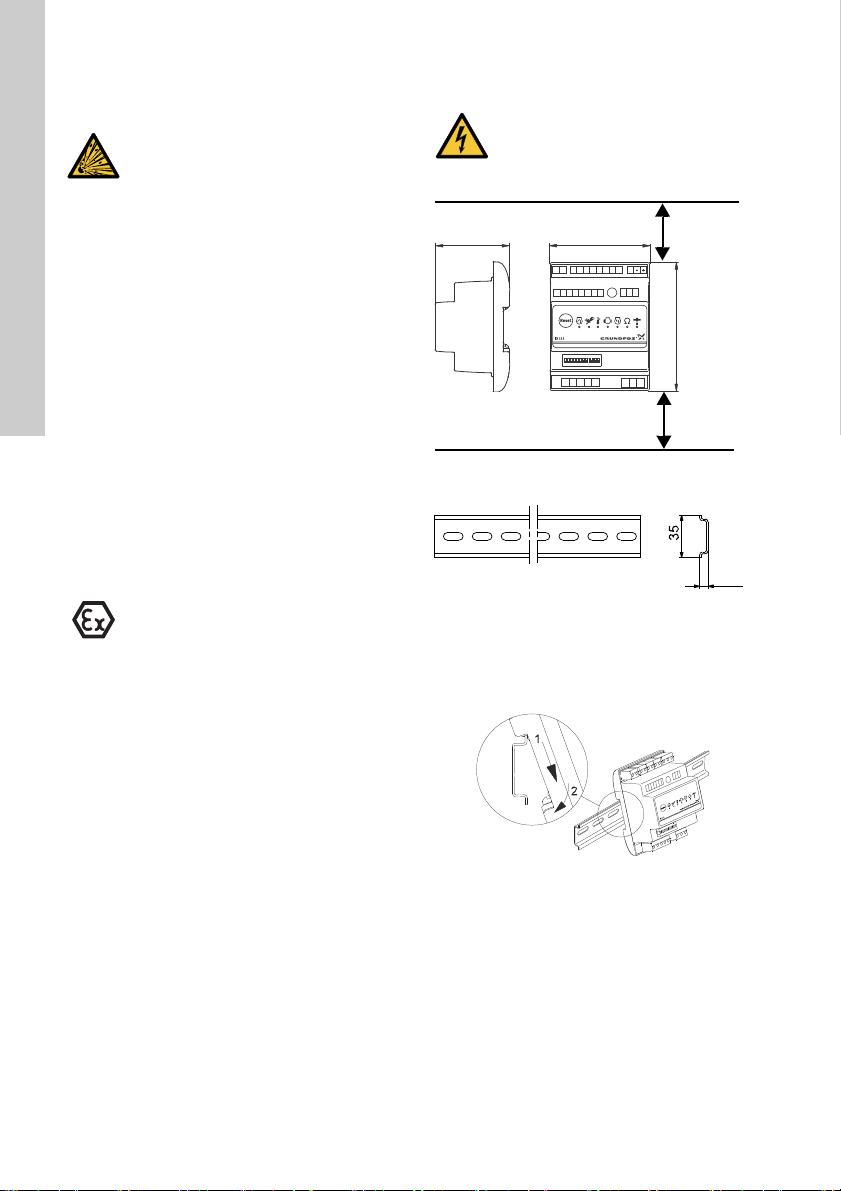
Fig. 1 Module and DIN rail
IO 113 is prepared for mounting on a 35 mm DIN rail
(EN 50022).
Fit the IO 113 module by hooking the top onto the
DIN rail and clicking the bottom onto the rail.
Fig. 2 Mounting on DIN rail
The IO 113 module can be removed by pushing it
upwards and free of the DIN rail.
CAUTION
Explosive environment
Minor or moderate personal injury
- Do not install IO 113 in potentially
explosive environments.
ATEX/IEC Ex protection can be activated
by means of DIP switch 10. This enables
additional alarms, see section 4.8 ATEX/
IEC Ex protection.
DANGER
Electric shock
Death or serious personal injury
- Always install the product in a suitable
cabinet.
TM05 1994 4111 - TM03 0934 0805TM05 1967 4111
90
116
66.5
PET1 T2 G1 A1 G2 A2 K1 K2 R1 R2
D1 D2 D3 D4 D5D6 D7 D8
P1 P2 P3 P4 P5
AYB
I1 I2 I3
ON DIP
12345678910
11 12
Min. 30 mm
Min. 30 mm
35 mm DIN rail (EN 50022)
Recommended height: 7.5 mm
7.5

English (GB)
5
3.4 EMC-compliant installation
It is especially important to ensure EMC-compliant
installation of pumps with a frequency converter or
when using more than one IO 113 in a cabinet.
The following rules must be observed:
• Connect the cable screen to earth.
• Do not twist screen ends as this will destroy the
screening effect at high frequencies. Use cable
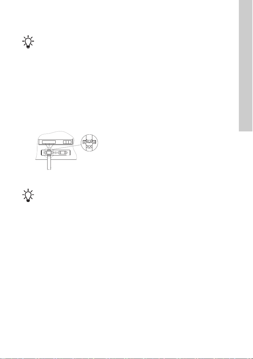
clamps as shown in fig. 3.
• Ensure a good electrical contact from the
mounting plate through the mounting screws to
the metal cabinet of the frequency converter.
• Use toothed washers and a galvanically
conducting mounting plate.
Fig. 3 Screen fixed with cable clamp
If the motor cable between the pump and
any frequency converter is more than 10
metres long, we recommend that you
equip the frequency converter with an
output filter to prevent incorrect analog
measurements.
TM05 4056 2012
Screen both ends of the motor cable to
earth. The insulating plastic layer between
screen and sheath must be as close to the
terminals as possible.
P1 . . . P5
I1 I2 I3

English (GB)
6
3.5 Electrical connection
3.5.1 Wiring diagrams
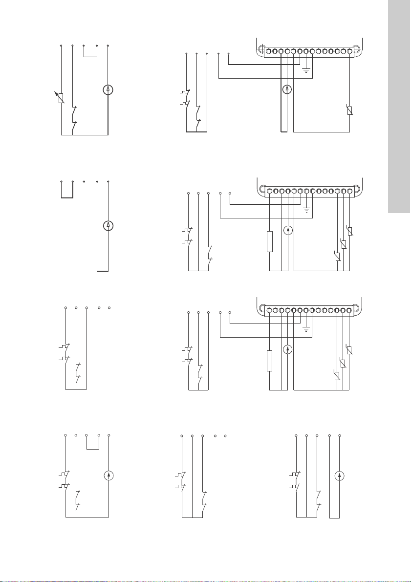
The wiring diagrams below show the regular applications of WIO/WIA sensors, moisture switch, thermal
switches, Pt100/Pt1000/PTC sensors, as well as sensor monitoring board SM 113 with speed sensor, vibration
sensor and components.
For information about setting the DIP switches, see section 4.2 DIP switch configuration.
TM05 2493 0112
TM05 2794 0612
PA - Thermal switches, Pt1000
sensor, moisture switch, WIO/
WIA sensor
PB - With SM 113. Thermal switch, moisture switch, WIO/WIA
sensor, Pt100/Pt1000 sensor
P1 P2 P5P3 P4
IO 113
WIO / WIA
Pt1000
ON
12
Moisture switch
Thermal
switches
1234567891011121314
SM 113
P1 P2 P5P3 P4
Pt100 / Pt1000
WIO / WIA
IO 113
Moisture switch
Thermal
switches
TM05 2494 0112
TM05 2795 0612
PA - Thermal switches, PTC
sensor, moisture switch, WIO/
WIA sensor
PB - With SM 113. Thermal switches, moisture switch, WIO/WIA
sensor, Pt100/Pt1000 sensors
P1 P2 P5P3 P4
IO 113
WIO / WIA
PTC
ON
12
Moisture switch
Thermal
switches
1234567891011121314
SM 113
P1 P2 P5P3 P4
Pt100 / Pt1000
WIO / WIA
IO 113
Moisture switch
Thermal
switches
TM05 2789 0612
TM05 2796 0612
PA - Thermal switches, moisture
switch, WIO/WIA sensor
PB - With SM 113. Thermal switches, moisture switch, WIO/WIA
sensor, Pt100/Pt1000 sensors, vibration sensor
P1 P2 P5P3 P4
IO 113
WIO / WIA
ON
12
Moisture switch
Thermal
switches
1234567891011121314
SM 113
P1 P2 P5P3 P4
Pt100 / Pt1000
WIO / WIA
IO 113
Moisture switch
Thermal switches
Vibration
sensor

English (GB)
7
TM05 2790 0612
TM05 2798 0612
PA - PTC sensor, moisture
switch, WIO sensor
PB - With SM 113. Thermal switches, moisture switch, WIO/WIA
sensor, Pt100/Pt1000 sensors
P1 P2 P5P3 P4
PTC
WIO / WIA
2
Moisture switch
1234567891011121314
P1 P2 P5P3 P4
WIO / WIA
Pt100 / Pt1000
Thermal
switches
Moisture switch
TM05 4507 2412
TM06 1788 2914
PA - WIO/WIA sensor PC - IO 113 with SM 113 module
P1 P2 P5P3 P4
WIO / WIA
12 3456 7891011121314
P1 P2 P3 P4 P5
+-
Moisture switch
Thermal
switches
Vibration
sensor
Pt100/Pt1000
WIO/WIA
TM06 1791 2914
TM06 1789 2914
PA - IO 113 without a WIO/WIA
sensor PB - IO 113 with SM 113 module
P1 P2 P3 P4 P5
12 3456 7891011121314
P1 P2 P3 P4 P5
+-
Moisture switch
Thermal
switches
Vibration
sensor
Pt100/Pt1000
WIO/WIA
TM06 1792 2914
TM06 1793 2914
TM06 1790 2914
PA - With WIO/WIA sensor PD - Without WIO/WIA sensor PD - With WIO/WIA sensor
P1 P2 P3 P4 P5
P1 P2 P3 P4 P5
P1 P2 P3 P4 P5

English (GB)
8
3.5.2 Electrical connection
All terminals are rated for maximum 8 A.
Terminals 1, 2, 3, 5, 10 and 11 are for wire size 0.08
- 3.3 mm2 (AWG 28-12); terminal 17 is for wire size
0.08 - 1.3 mm2 (AWG 28-16). For voltage rating of
the individual terminals, see section 3.5 Electrical
connection.
For terminals 5 and 17, one 3-hole socket and one
8-hole socket are provided as accessories in the
package.
Terminals T1 and T2 are normally connected to 220-
240 VAC. See fig. 20, pos. 1.
Terminal I3 may be connected to up to 600 VAC. See
fig. 20, pos. 10 and the diagrams at the end of these
instructions.
4. Configuring the product
4.1 Potentiometer
Set the warning limit for stator insulation resistance
by means of a potentiometer. See fig. 20 (4). The
warning limit can be set between 1 and 10 MΩ. The
alarm limit is 1 MΩ.
Fig. 4 Potentiometer
4.2 DIP switch configuration
IO 113 must be configured for the connected pump
by means of the DIP switches. See fig. 20 (12).
Fig. 5 Shows that all DIP switches are in OFF
position
A configuration alarm will be given in the following
cases:
• The configuration does not correspond to the
pump connected.
• The configuration fault is of safety-related
importance (see section 6.7 Approval).
A configuration warning will be given if the
configuration fault is of function-related importance
(see section 6.7 Approval).
The insulation between the cabinet in
which the module is fitted and the sensor
input terminals must have a dielectric
strength of 2210 VAC, or the cabinet must
be connected to earth.
External controllers connected to the IO
113 module via the RS-485 connection
must meet the requirements of IEC 60950-
1 or 61010-1 (USA: UL 60950-1).
If SM 113 is used in the installation,
connect a PTC sensor to IO 113.
TM03 3415 0306
TM05 1978 4111
1 MΩ 10 MΩ
ON DIP
123456789101112

English (GB)
9
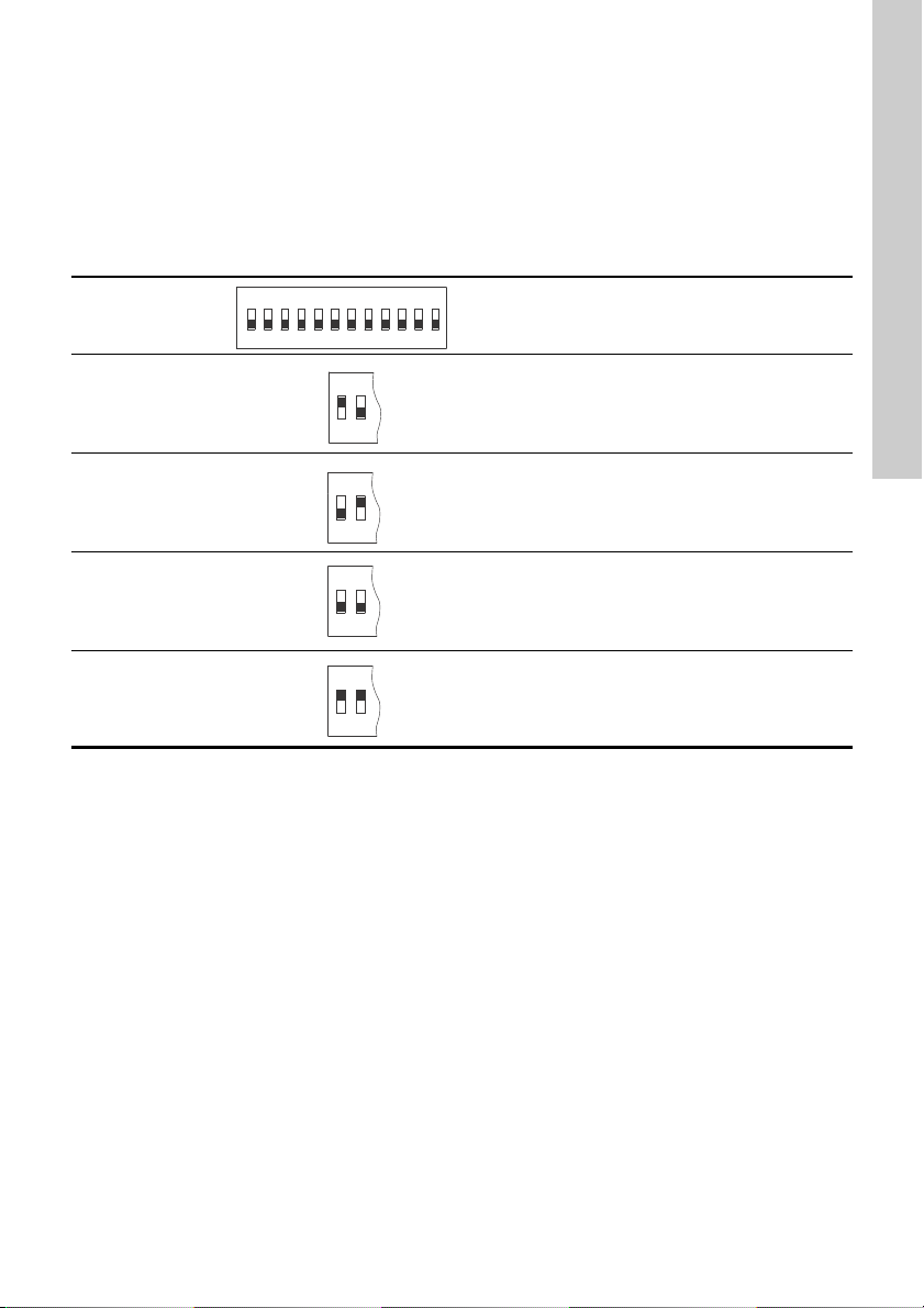
4.3 Pump variant
IO 113 must be configured for the connected pump.
The pump type designation indicates an A, B, C or D.
Example 1, internal wiring:
SE1 80 80 40 A Ex 4 5 1D
Example 2, external wiring:
SE2.90.250.2250.4.S.496.Ex.S.5.13.C.Q.S
The letters A and C in the examples can be found on
the pump nameplate and must be referred to when
setting DIP switches 1 and 2.
Pump variant Description
PA
IO 113 without SM 113.
Sensors are connected directly to IO 113.
Position 1 ON
Position 2 OFF
PB
IO 113 with SM 113.
Sensors are connected to SM 113.
Position 1 OFF
Position 2 ON
PC
IO 113 without SM 113.
For SE/SL 9-30 kW pumps only.
Sensors are connected directly to IO 113.
Position 1 OFF
Position 2 OFF
PD
IO 113 without SM 113.
The WIO/WIA sensors are connected directly to the
pump.
Position 1 ON
Position 2 ON
ON DIP
123456789101112
ON
12
ON
12
ON
12
ON
12

English (GB)
10
4.4 Address for bus communication
IO 113 can communicate with control systems via a
bus connection. For the purpose of bus
communication, IO 113 is slave. As a control system
must be able to identify the slave units with which it
communicates, the IO 113 modules must have
unique addresses. An address between 32 and 231
can be selected. By default, the address is set to
231.
When an SM 113 is used together with an IO 113 as
a pair, SM 113 is slave. In one control system, a
maximum of seven pairs may be used. Each IO 113
must be identified by a unique address, configured
by means of DIP switches 3, 4 and 5. See the below
table.
Another way to set the unique address of an SM 113
in the control system is by bus. In this case, DIP
switches 3, 4 and 5 must be toggled to OFF.
Address Description
40 IO 113 address 1
41 IO 113 address 2
42 IO 113 address 3
43 IO 113 address 4
44 IO 113 address 5
45 IO 113 address 6
Address set by bus
Unique address for IO 113 set in the control
system via bus.
Default address: 231.
ON DIP
123456789101112
345
345
345
345
345
345
345
Altri manuali per IO 113
5
Indice
Altri manuali Grundfos Sistema I/O
Manuali Sistema I/O popolari di altre marche

WAGO
WAGO 750-344 Manuale utente

Teknim
Teknim TWM-1887 Manuale di istruzioni

Intelligent Appliance
Intelligent Appliance IA-2662-E Manuale utente

BERGHOF
BERGHOF ECC DIO 16/16 Manuale di istruzioni

Advantech
Advantech PCM-27J3AU Manuale di installazione e funzionamento

Festo
Festo CP-E08-M12-CL Manuale utente