
GSi Autoflow 2000 Series Manuale utente
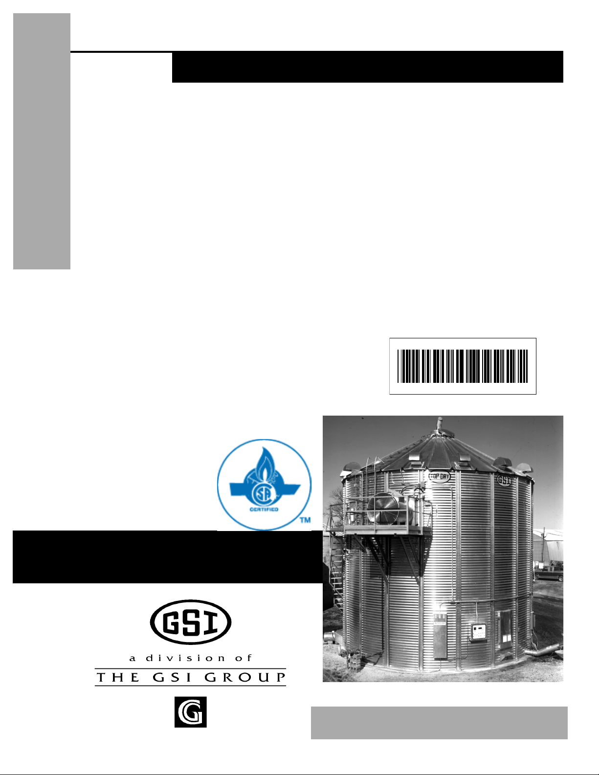
2000 Autoflow
1
1
Series 2000 Autoflow
Fan/Heater and Control
Installation Instructions
Installation
Manual
PNEG-900
PNEG-900

2000 Autoflow
2
2
This equipment shall be installed in accordance iwth the current INSTALLATIONCODESFOR
GASBURNINGAPPLICANCESANDEQUIPMENT,CAN1_B149.1andB149.2,or applicable
provincial regulations which should be carefully followed in all cases. Authorities having
jurisdiction shuld be consulted before installations are made.

2000 Autoflow
3
RoofWarning,Operation & Safety................................................................................4
SafetyAlertDecals.......................................................................................................5
SafetyPrecautions........................................................................................................6
SafetySign-off Sheet...................................................................................................7
an/HeaterandControlBoxMounting..............................................................................8
AutoflowControlBoxBoltPattern.................................................................................10
Fill System Control Box Mounting.............................................................................11
FillSystem Control Bolt Pattern..................................................................................12
Actuator Control Box Mounting.................................................................................13
Multi-GrainTemperatureSensorWiring.........................................................................15
GrainTemperatureSensor Mounted to LevelingBand Post........................................16
Close-upofGrainTemperatureSensorWiring.............................................................17
PlenumTemperatureSensorInstallation..........................................................................18
Airswitch Installation.................................................................................................19
WetSupplyRotary Switch..........................................................................................21
Storage Chamber High Limit Rotary Switch Installation...........................................22
DryingChamber Rotary Switches...............................................................................25
Drying Chamber Low-Level Rotary Switch Installation............................................26
Drying Chamber High-Level Rotary Switch Installation...........................................28
DryingChamber Overflow Switch Installation.............................................................30
LPFuelSpecificationsandRecommendations................................................................32
NGFuelSpecificationsandRecommendations...............................................................33
cuit Runs................................................................................................................34
ElectricalPowerSupply...................................................................................................35
Ground Rod.....................................................................................................36
MotorWiring........................................................................................................37
MainPowerSchematic.................................................................................................37
ElectricalLoadInformation.............................................................................................38
Wire Size Information................................................................................................39
Fill System Control Box Electrical Load Information.................................................40
AutoflowtoMaster Fan/Heater Unit Interconnect...........................................................42
Autoflow to Actuator Interconnect.............................................................................43
Autoflow to Wet Supply Rotary Switch Interconnect.................................................44
Autoflow to Storage Chamber Rotary Switch Interconnect.......................................45
AutoflowtoDrying Chamber Rotary Switches Interconnect..........................................46
Autoflow to Fill System Control Box Interconnect....................................................48
Autoflow to Ground Interconnect............................................................................ 49
Masterto Slave Interconnect......................................................................................50
SlavetoSlave Interconnect.........................................................................................51
BatteryHookUp.........................................................................................................52
DumpChute Cable Installation...................................................................................53
Wrranty.......................................................................................................................55
TABLE OF CONTENTS
2000 Autoflow
4
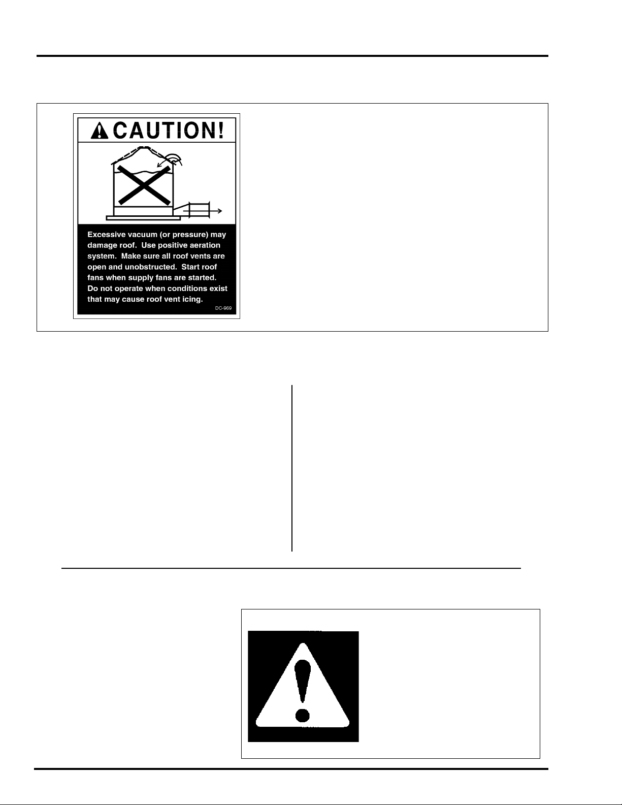
Roof Damage Warning and Disclaimer
WARNING! BE ALERT!
Personnel operating or working
around electric fans should read this
manual. This manual must be
delivered with the equipment to its
owner. Failure to read this manual
and its safety instructions is a misuse
of the equipment.
The symbol shown is used to call your
attentionto instructionsconcerning your
personal safety. Watch for this sym-
bol; it points out important safety pre-
cautions. It means "ATTENTION",
"WARNING", "CAUTION", and
"DANGER". Read the message and
be cautious to the possibility of per-
sonal injury or death.
Safety Alert Symbol
GSI DOES NOT WARRANT ANY ROOF DAMAGE
CAUSEDBY EXCESSIVE VACUUM OR INTERNAL
PRESSURE FROM FANS OR OTHER AIR MOVING
SYSTEMS. ADEQUATE VENTILATION AND/OR
"MAKEUPAIR"DEVICESSHOULDBEPROVIDED
FOR ALL POWERED AIR HANDLING SYSTEMS.
GSIDOESNOTRECOMMENDTHEUSEOFDOWN-
WARD FLOW SYSTEMS (SUCTION). SEVERE
ROOF DAMAGE CAN RESULT FROM ANY
BLOCKAGE OF AIR PASSAGES. RUNNING FANS
DURINGHIGH HUMIDITY/COLD WEATHERCON-
DITIONS CAN CAUSE AIR EXHAUST OR INTAKE
PORTS TOFREEZE.
Thank you for choosing a Top Dry Series 2000
Autoflow unit. It is designed to give excellent per-
formance and service for many years.
Thismanualdescribes theinstallationfor all stan-
dard production Top Dry Series 2000 single fan,
multi-fan and 2000 Series Autoflow units. Differ-
ent models are available for liquid propane or natu-
ral gas fuel supply, with either single phase 230 volt,
or three phase 208, 220, 380, 460 or 575 volt electri-
cal power.
The principal concern of the GSI Group, Inc.
("GSI") is your safety and the safety of others asso-
Series 2000 Autoflow Installation & Operating Instructions
ROOF WARNING, OPERATION & SAFETY
As owner and/or operator, it is your responsibil-
ity to know what requirements, hazards and precau-
tions exist, and to inform all personnel associated
withthe equipment, or who are in the fan area. Avoid
any alterations to the equipment. Such alterations
may produce a very dangerous situation, where se-
rious injury or death may occur.
ciated with grain handling equipment. This manual
is written to help you understand safe operating pro-
cedures, and some of the problems that may be en-
countered by the operator or other
personnel.
2000 Autoflow
5
The GSI Group, Inc. recom-
mends contacting your local
power company, and having a
representativesurvey your instal-
lation so the wiring is compatible
with their system, and adequate
power is supplied to your unit.
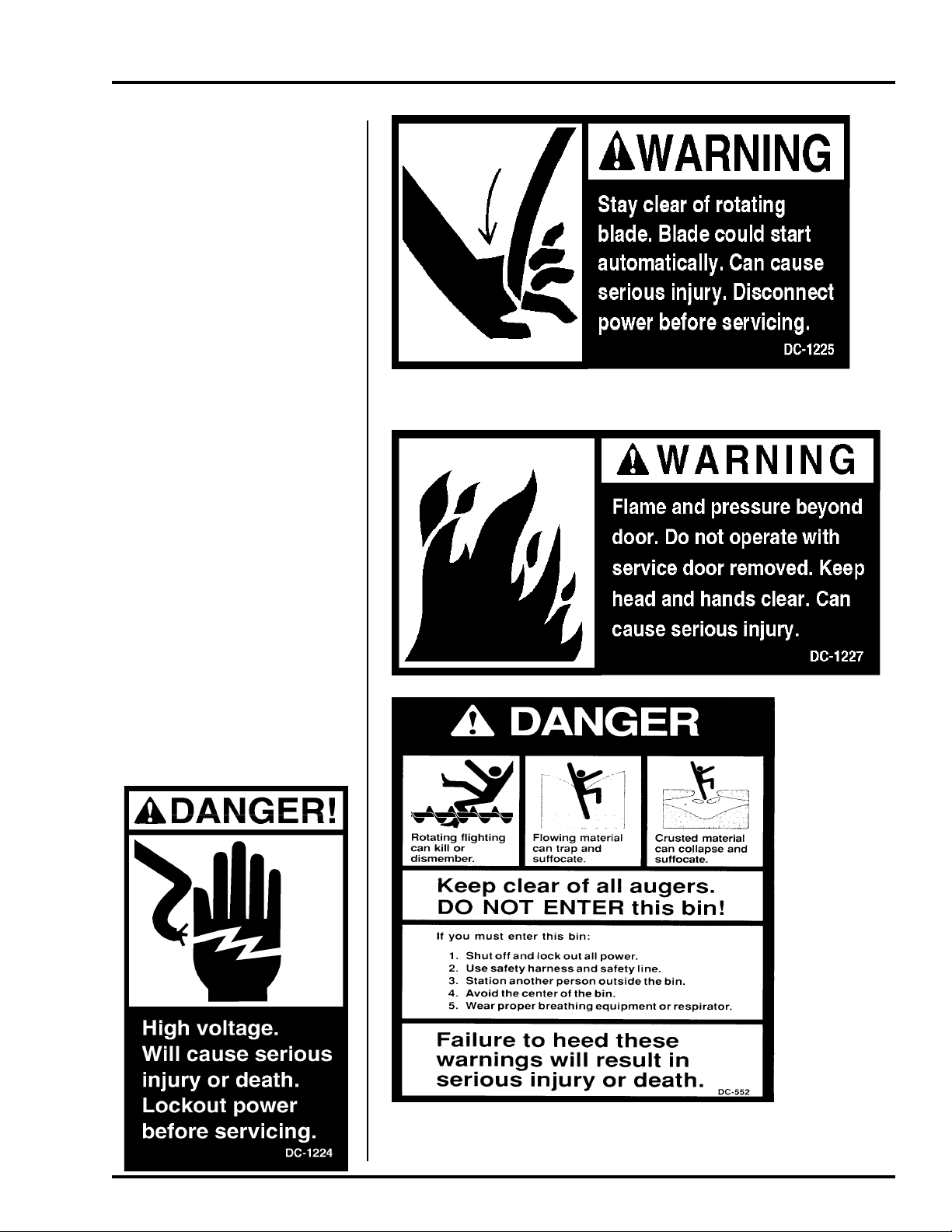
Safety decals should be read
and understood by all people in
the grain handling area. The ro-
tating blade, fire warning decals
and voltage danger decal must be
displayedon thefan can. The bot-
tom right decal should be present
on the inside bin door cover of
the two ring door, 24" porthole
door cover and the roof manway
cover.
If a decal is damaged or is
missing contact:
The GSI Group, Inc.
1004 E. Illinois St.
Assumption, IL 62510
217-226-4421
A free replacement will be sent to
you.
SAFETY

2000 Autoflow
6
1. Read and understand the operating manual before trying to operate the
dryer.
2. Power supply should be OFF for service of electrical components. Use
CAUTION in checking voltage or other procedures requiring power to
be ON.
3. Check for gas leaks at all gas pipe connections. If any leaks are de-
tected, do not operate the dryer. Shut down and repair before further
operation.
4. Never attempt to operate the dryer by jumping or otherwise bypassing
any safety devices on the unit.
5. Set pressure regulator to avoid excessive gas pressure applied to burner
during ignition and when burner is in operation. Do not exceed maxi-
mum recommended drying temperature.
6. Keep the dryer clean. Do not allow fine material to accumulate in the
plenum or drying chamber.
7. Use CAUTION in working around high speed fans, gas burners, augers
and auxiliary conveyors which START AUTOMATICALLY.
8. Donotoperateinanyareawherecombustiblematerialwillbedrawninto
the fan.
9. Beforeattempting to remove and reinstall any propellor,make certain to
read the recommended procedure listed within the servicing section of
the manual.
10. Clean grain is easier to dry. Fine material increases resistance to airflow
and requires removal of extra moisture.
Proper Use of Product
This product is intended for the use of drying small grains only.
Any other use is a misuse of the product!
This product has sharp edges! These sharp edges may cause serious
injury. To avoid injury handle sharp edges with caution and use proper
protective clothing and equipment at all times.
Guards are removed for illustration purposes only. All guards must be
in place before and during operation.
Use Caution in the
Operation of this
Equipment
The design and manufacture of this
dryer is directed toward operator
safety. However, the very nature
of a grain dryer having a gas burner,
highvoltageelectrical equipment and
high speed rotating parts, does
present a hazard to personnel, which
can not be completely safeguarded
against, without interfering with ef-
ficient operation and reasonable ac-
cess to components.
Use extreme caution in working
around high speed fans, gas-fired
heaters,augers and auxiliary convey-
ors, which may start without warn-
ing when the dryer is operating on
automatic control.
READTHESEINSTRUCTIONS
BEFOREOPERATIONAND SERVICE
SAVEFORFUTUREREFERENCE
Continued safe, dependable opera-
tion of automatic equipment de-
pends, to a great degree, upon the
owner. For a safe and dependable
dryingsystem,follow the recommen-
dationswithin thismanual, and make
it a practice to regularly inspect the
operation of the unit for any devel-
opingproblems orunsafe conditions.
Take special note of the safety pre-
cautionslisted above before attempt-
ing to operate the dryer.
KEEP THE DRYER CLEAN
DO NOT ALLOW FINE
MATERIAL TO ACCUMULATE
IN THE PLENUM CHAMBER
OR SURROUNDING THE OUT-
SIDE OF THE DRYER
SAFETY PRECAUTIONS

2000 Autoflow
7
Date Employer’ s Signature Employee
________________________________________________________________________________________________________________________
_________________________________________________________________________________________________________________________
________________________________________________________________________________________________________________
___________________________________________________________________________________________________________________________
________________________________________________________________________________________________________________________
_____________________________________________________________________________________________________________________________
__________________________________________________________________________________________________________________________
_______________________________________________________________________________________________________________________________
_____________________________________________________________________________________________________________________________
______________________________________________________________________________________________________________________________
___________________________________________________________________________________________________________________________
______________________________________________________________________________________________________________________
_________________________________________________________________________________________________________________________
_____________________________________________________________________________________________________________________
______________________________________________________________________________________________________________________
_________________________________________________________________________________________________________________________
______________________________________________________________________________________________________________________
_______________________________________________________________________________________________________________________
______________________________________________________________________________________________________________________
______________________________________________________________________________________________________________________
_____________________________________________________________________________________________________________________
________________________________________________________________________________________________________________________
______________________________________________________________________________________________________________________
_____________________________________________________________________________________________________________
_______________________________________________________________________________________________________________________
_____________________________________________________________________________________________________________________
SAFETY SIGN-OFF SHEET
Employees working on or around grain drying equipment
must read this manual and sign-off on this sheet.
2000 Autoflow
8
Fan and Heater Mounting
1. Inspect the fan platform for properinstallation
per instructions in the Top Dry erection manual.
2. Raise the Top Dry fan and heater units to the
plat form. Use the table to the right to deter-
mine the height of the platform from the base of the
TopDry unit.
3. Mount the Top Dry fan and heater units to the
bin entrance sheets. Fan legs should set on the
plat form.
Top Dry Bin Eave Height
Number
of Rings
5
6
7
8
9
10
11
Eave
Height
18’-5”
22’-1”
25’-9”
29’-5”
33’-1”
36’-9”
40’-5”
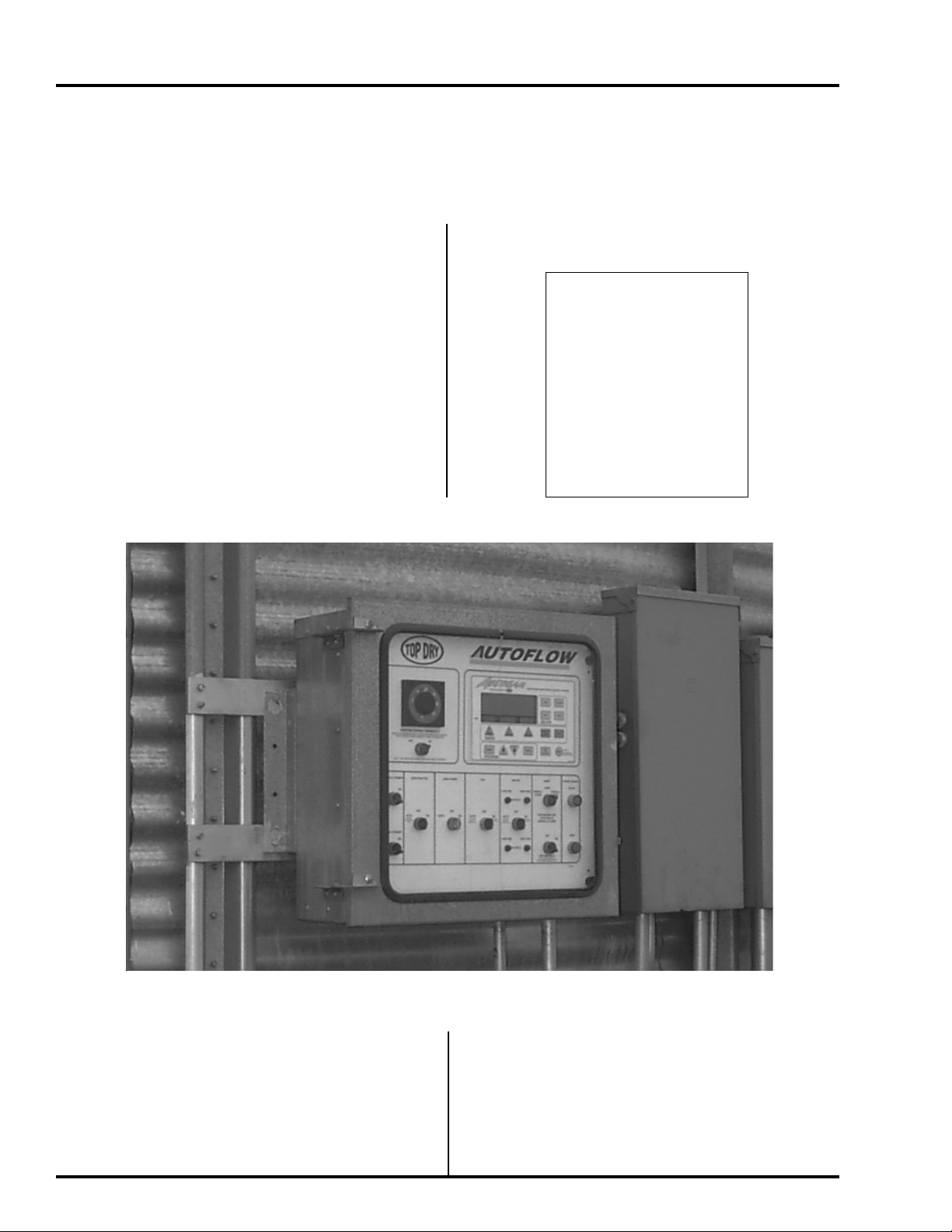
Autoflow Control Box Mounting
1. The Autoflow Control Box should be
mounted at eye-level. Make sure to mount
the Autoflow control box so that the fan
and heater unit(s) are in view.
Autoflow Control box mounted on bin.
2. Keep in mind that wire will be used to inter
connect the Autoflow control Box with the
INSTALLATION
fan and heater unit(s), Fill System Control
Box, Actuator and all rotary switches.
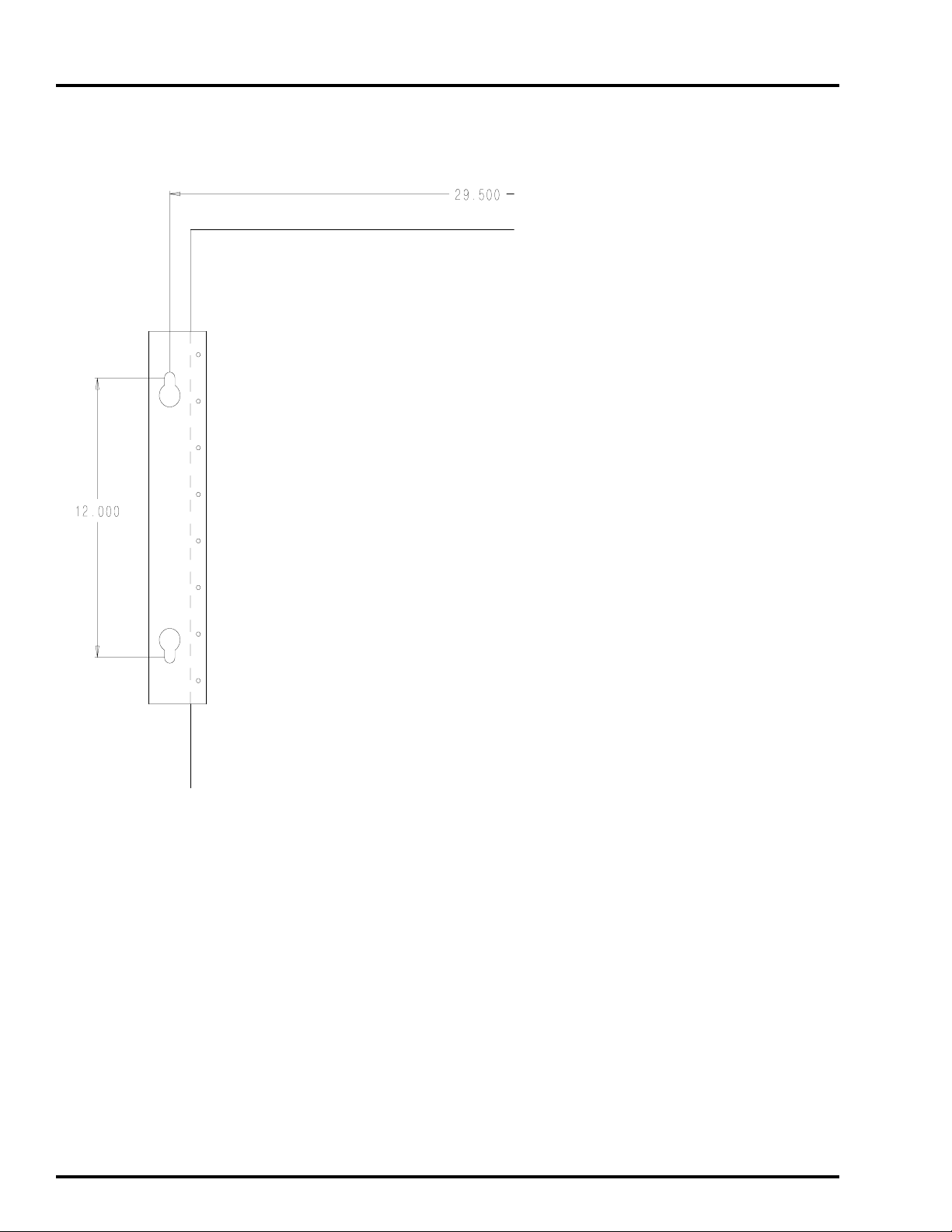
3. Use the hole pattern in Figure 1 to drill holes
for mounting the Autoflow Control Box.
Note:Do not installthis control panelnear any
Transfomers orany otherdevice thatwill
produceanElectro MagneticField.

2000 Autoflow
9
Component Placement
INSTALLATION
2000 Autoflow
10
Series 2000 Autoflow Control Box Bolt Pattern
Figure 1: Illustration of the bolt pattern for the Autoflow control box.
INSTALLATION
Indice
Altri manuali GSi Stufa

GSi
GSi PNEG-377 Manuale utente

GSi
GSi Airstream 2000 Series Manuale utente

GSi
GSi 2000 Series Manuale utente

GSi
GSi PNEG-012 Series Manuale del proprietario

GSi
GSi TF-2024-1C Manuale utente

GSi
GSi TopDry 2000 Series Manuale utente

GSi
GSi 2000 Series Manuale utente

GSi
GSi 2003 Series Manuale utente

GSi
GSi 10 HP Guida
Manuali Stufa popolari di altre marche


Empire Heating Systems
Empire Heating Systems WCC65 Manuale utente

Wetekom
Wetekom 92 86 43 Manuale utente

Desa
Desa SPC170-F Manuale utente

Watlow
Watlow Watrod Electric Tubular Heaters Manuale utente

Haverland
Haverland ECO-DRY GPS Series Manuale elenco delle parti

Stelpro
Stelpro ASILVC2060 Series Manuale utente