GSS SMCIP 401 ASI Manuale utente

Assembly Instruction
SMCIP 401 ASI

- 2 - SMCIP 401 ASI
Contents
1 Safety regulations and notes ........................................................................4
2 General information ....................................................................................5
2.1 Packing contents ............................................................................5
2.2 Meaning of the symbols used ..........................................................5
2.3 Technical data ...............................................................................5
2.4 Description ...................................................................................7
Block diagram ...............................................................................7
Descrambling programmes of an existing plant .................................8
Extending an existing plant with descrambling the extended programmes ........9
General ......................................................................................10
3 Assembly ..................................................................................................11
3.1 Installing the device .....................................................................11
3.2 device overview ..........................................................................12
3.3 Connecting the device ..................................................................12
Potential equalisation (PE) .............................................................12
Signal Connections ......................................................................12
If a free input is available at the multiswitch: ..............................13
If no free input is available at the multiswitch: ............................13
3.4 Retrofitting a CA module ..............................................................15
3.5 Software .....................................................................................16
Software query............................................................................16
Software update ..........................................................................16
4 The control panel at a glance .....................................................................19
4.1 Control panel ..............................................................................19
4.2 Menu items .................................................................................19
5 Programming ............................................................................................20
5.1 Notes on frequency setting ...........................................................20
5.2
Notes on level setting ...................................................................22
Level too high ..............................................................................22
Level too low ...............................................................................22
Thus, the level must be adjusted .....................................................22
5.3 Programming procedure ...............................................................23
5.4 Programming the cassette ............................................................24
Status menu ................................................................................25
Output mode ...............................................................................26
Output parameter, level ................................................................26
Modulator frequency (SAT IF) ...................................................27

- 3 - SMCIP 401 ASI
Output symbol rate, Spectral position, code rate (FEC) ................27
ASI input selection .......................................................................28
Input parameter ...........................................................................29
LNB oscillator frequency / DiSEqC commands ...........................29
Input symbol rate ....................................................................31
Input frequency ......................................................................31
Operation with a CA module ...................................................32
Station selection .....................................................................32
Output data rate ..........................................................................34
Transport stream ID and ORGNET-ID ..............................................35
CA data packets .........................................................................35
PID monitoring ............................................................................36
CA module .................................................................................37
Factory reset ...............................................................................38
Saving data ................................................................................38

- 4 - SMCIP 401 ASI
1 safety regulations and notes
• This device is subject to the provisions of protection class II .
• Do not operate the device without equipotential bonding!
• The standards EN/DIN EN 50083 resp. IEC/EN/DIN EN 60728 must be
observed
.
• Observe the relevant standards, regulations and guidelines on the installa-
tion and operation of antenna systems.
• Observe the relevant VDE regulations.
• Do not perform installation and service work during thunderstorms.
• Assembly, installation and servicing should be carried out by authorised
electricians.
• Switch off the operating voltage of the system before beginning with assem-
bly or service work or pull out the mains plug.
• Install the system so it will not be able to vibrate…
- in a dust-free, dry environment
- in such a manner that it is protected from moisture, fumes, splashing wa-
ter and dampness
- somewhere protected from direct sunlight
- not within the immediate vicinity of heat sources
- in an ambient temperature of 0 °C to +40 °C. In case of the formation of
condensation wait until the system is completely dried.
• Ensure that the device is adequately ventilated.
Do not cover the ventilation slots.
•
Do not install the
device
in cabinets or recesses which are not ventilated.
• Do not place any vessels containing liquids on the device.
•
Do not place anything on the device which could initiate fires (e.g. candles).
•
Due to the risk of fires caused by lightning strikes, we recommend that all
mechanical parts (e.g. distributor, equipotential bonding rail, etc.) be mounted
on a non-combustible base. Wood panelling, wooden beams, plastic covered
panels and plastic panels are all examples of combustible bases.
• Avoid short circuits
• No liability is accepted for any damage caused by faulty connections or
inappropriate handling.
• Test the software versions of the device and update them if necessary. The
current software versions can be found at "www.mygss.eu".
Take action to prevent static discharge when working at the device!

- 5 - SMCIP 401 ASI
Electronic devices should never be disposed of in the household rubbish. In accordance
with directive 2002/96/EC of the European Parliament and the European Council from
January 27, 2003 which addresses old electronic and electrical devices, such devices
must be disposed of at a designated collection facility. At the end of its service life,
please take your device to one of these public collection facilities for proper disposal.
2 general information
2.1 PaCking Contents
1 SMCIP 401 ASI
1 Assembly instructions
2.2 meaning of the symbols used
Important note
Danger by electrical shock
—> General note
• Performing works
2.3 teChniCal data
The devices meet the following EU directives:
2011/65/EU, 2014/30/EU, 2014/35/EU
The product fulfils the guidelines and standards for CE labelling (page 39).
Unless otherwise noted all values are specified as "typical".
RF input DVB-S2
Frequency range: ....................................................... 950 … 2150 MHz
Level range: ............................................................ 60 dBμV … 80 dBμV
DVB-S modes: .....................................DVB-S 1/2 , 2/3 , 3/4 , 5/6 , 7/8
DVB-S2 modes: .......QPSK 1/2 , 3/5 , 2/3 , 3/4 , 4/5 , 5/6 , 8/9 , 9/10
8PSK 3/5 , 2/3 , 3/4 , 5/6 , 8/9 , 9/10
16APSK 2/3, 3/4, 4/5, 5/6, 8/9, 9/10
32APSK 3/4, 4/5, 5/6, 8/9, 9/10

- 6 - SMCIP 401 ASI
Symbol rate: ..................................................... QPSK: 1 … 53 MSymb/s
8PSK: 1 … 45 MSymb/s
16APSK: 1 … 35 MSymb/s
32APSK: 1 … 28 MSymb/s
Net data rate per tuner .............................................. maximum 72 Mbit/s
DiSEqCTM*: ............................ 1.1 (16 Satellites with 4 levels, max. 60 mA)
*DiSEqCTM is a trademark of EUTELSAT
ASI
Standard: .....................................................................DIN EN 50083-9
Format: ..............................................................MPEG ISO IEC 13818-1
Output data rate: ............................................... maximum 72.573 Mbit/s
dependent on the DVB-S output parameter settings and the CA module
Level (input / output): .................................................... 800 mVPP ± 10%
Return loss (input):...............................................> 17 dB (5 … 270 MHz)
RF output DVB-S
Frequency range: ....................................................... 950 … 2250 MHz
Level range: ............................................................ 48 dBμV … 95 dBμV
(Adjustable attenuation in 47 dB steps)
DVB-S modes: .....................................DVB-S 1/2 , 2/3 , 3/4 , 5/6 , 7/8
Symbol rate: ..................................................... QPSK: 5 … 45 MSymb/s
FEC:............................................................ 1/2 , 2/3 , 3/4 , 5/6 , 7/8
Data rate. ......................................................... maximum 72.573 Mbit/s
Rolloff: ...........................................................................................0.25
Connections
SAT inputs: .............................................................................4 F sockets
Loop input (LNB): .................................................................... 1 F socket
SAT output: ............................................................................ 1 F socket
ASI input: ..........................................................................1 BNC socket
ASI output: ......................................................................... 1 BNC socket
Micro USB socket: ...................................................... for software update
Common Interface: .......................1 (several channels can be descrambled)
Power Supply
Mains voltage: .................................................... 220–240V~, 50/60 Hz

- 7 - SMCIP 401 ASI
2.4 desCriPtion
The transmodulator converts channels from up to four DVB-S/DVB-S2 trans-
ponders (four tuners A…D or three tuners A…C and the ASI input) into one
DVB-S transponder.
Using an adequate CA module the scrambled signals contained in this mul-
tiplex (MUX) can be descrambled. The number of signals to be descrambled
depends on the CA module and the smart card.
bloCk diagram
Tuner "A"
SAT IN "A"
LNB IN
SAT Output
Tuner "D"
CA-Modul
CA module
Tuner "B"
Tuner "C"
SAT IN "B"
SAT IN "C"
SAT IN "D"
MUX Combiner
DVB-S
Modulator
47 dB
Attenuator
ASI IN
ASI Output
The four tuners receive their input signal from the outputs of a multiswitch.
In addition it is possible to feed in the ASI input signal instead of the tuner D
signal. The stations selected via the station selection menu will be multiplexed,
if necessary descrambled and modulated as DVB-S transponder.
—> Note the maximum possible output data rate of 72.573 Mbits/s,
which depends on the DVB-S output parameter settings!
If only the ASI output is needed, the modulator can be switched off.
If no further input is free for the converted signal at the multiswitch, the cor-
responding satellite band can be multiplexed via the LNB input with the output
transponder of the GSS.mux and then feed into the multiswitch.

- 8 - SMCIP 401 ASI
desCr ambling Progr ammes of an existing Pl ant
Receiver
ASI inASI out

- 9 - SMCIP 401 ASI
extending an existing Pl ant with desCrambling the extended Progr ammes
Current plantExtension
ASI in
ASI out
The converted transponder must be fed into the SAT IF range with the same
frequency range.

- 10 - SMCIP 401 ASI
general
As signal source four Tuners (or instead of Tuner D the ASI input signal) are
available.
The status menu informs whether the tuners A…D are "locked"/"not locked" to
an input signal, if stations are selected in the menu Station selection:
DVB-S =>
A–cD
DVB-S
V 8
In this example …
… no station from tuner B is selected (indication "–"),
… stations from tuners A and D are selected and have reception (capitals),
… a station from tuner C is selected but reception is disturbed (lower case).
—> If the ASI input is selected instead of tuner D, its state is displayed
accordingly.
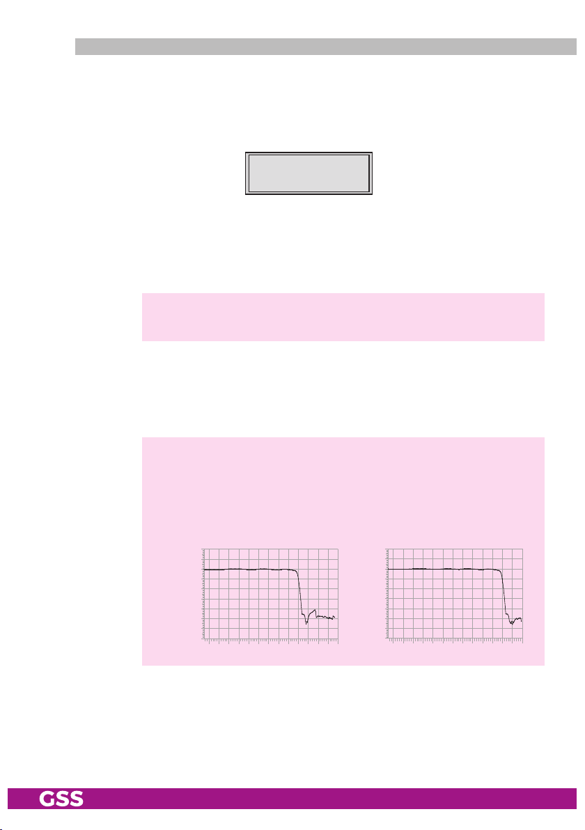
The output signal (new transponder) can be fit in a gap of a SAT IF range.
Therefore the corresponding range must be connected to the LNB input. At the
RF output the SAT IF range with fit in "new" transponder is present.
—> To ensure that an existing gap will not occupied by the satellite op-
erator, you can cut the upper end of the frequency spectrum in order
to generate your own gap by using a filter to the LNB input
9
. Our
filters lower the frequency spectrum from 1920 MHz ("GF1920")
resp. 2120 MHz ("GF2120") on to -30 dB.
-60
dB
-30
0
MHz
GF1920
190015001000
-60
dB
-30
0
2100 MHz15001000
GF2120
Indice
Altri manuali GSS Modulatore

GSS
GSS STI 1932 CT Manuale utente

GSS
GSS HDTV 610 CI TPS Manuale utente

GSS
GSS HMS 480 Manuale utente

GSS
GSS HDMT 1290 Manuale utente

GSS
GSS HDTA 614 C ASI Manuale utente

GSS
GSS HDTV 1000 FM Manuale utente

GSS
GSS HDMC 1000 FM Manuale utente

GSS
GSS HDTV 1000 ASI LAN Manuale utente

GSS
GSS STIM 1916 CT Manuale utente

GSS
GSS HDTV 1000 TD Manuale utente

GSS
GSS HD2CT 860 C Manuale utente

GSS
GSS HDM 660 T Manuale utente

GSS
GSS HDTA 614 T ASI Guida all'installazione

GSS
GSS HMM 470 Manuale utente

GSS
GSS PAMS 4000 Manuale utente

GSS
GSS HDMA 784 C ASI Manuale utente

GSS
GSS HDM 2380 P CI Manuale utente

GSS
GSS HDMC 1000 C Manuale utente

GSS
GSS HDMU 790 C Manuale utente

GSS
GSS PMDF 1000 Manuale utente