GUANDALINI PPK DJI PHANTOM 4 ADV Manuale utente

MANUAL AND DOCUMENTATION
ASSEMBLY MANUAL FOR KIT PPK ON
DJI PHANTOM 4 ADV/PRO
São Paulo, 09th April, 2020
Revisão nº 3
Manual developed by Guandalini Equipamentos Topográficos Technical Team

Sumário
1. KIT PPK...................................................................................................................... 2
2. ASSEMBLING THE KIT PPK ON PHANTOM 4 ADV/PRO............................................. 3
2.1. DRONE MOUNTING ........................................................................................... 3
2.1.1. STEP 1 ......................................................................................................... 3
2.1.2. STEP 2 ......................................................................................................... 3
2.1.3. STEP 3 ......................................................................................................... 4
2.1.4. STEP 4 ......................................................................................................... 5
2.1.5. STEP 5 ......................................................................................................... 7
2.1.6. STEP 6 ......................................................................................................... 9
2.1.7. STEP 7 ....................................................................................................... 11
2.1.8. STEP 8 ....................................................................................................... 12
2.2. MOUNTING ON THE REMOTE CONTROL......................................................... 13
2.3. PHANTOM 4 ADV/PRO BOX CUTTING ............................................................. 14
2.4. HOW TO CHARGE BATTERY FROM THE PPK KIT .............................................. 16
2.4.1. CHARGER IMAX B3.................................................................................... 16
2.4.2. AC/DC ADAPTER CHARGER....................................................................... 18
2.5. HOW TO MEASURE THE BATTERY CHARGE OF THE PPK KIT ........................... 19
2.5.1. LIPO BATTERY METER............................................................................... 20
3. CONFIGURAÇÃO DJI GO.......................................................................................... 22
4. FLIGHT PROCEDURES.............................................................................................. 25
4.1. STARTING THE BASE......................................................................................... 25
4.2. POSITIONING THE DRONE................................................................................ 25
4.3. HOW TO CONNECT THE CONTROL MODULE................................................... 26
4.4. INITIALIZING THE SYSTEM................................................................................ 27
4.5. SHUTTING DOWN THE SYSTEM ....................................................................... 29
MANUAL DE MONTAGEM KIT PPK NO
DJI PHANTOM 4 ADV/PRO
2
Av. Paulo VI, 1952 (novo n 184) • Sumaré • CEP 01262-010 • São Paulo • SP
(11) 4800-3157 • www.guandalinibr.com
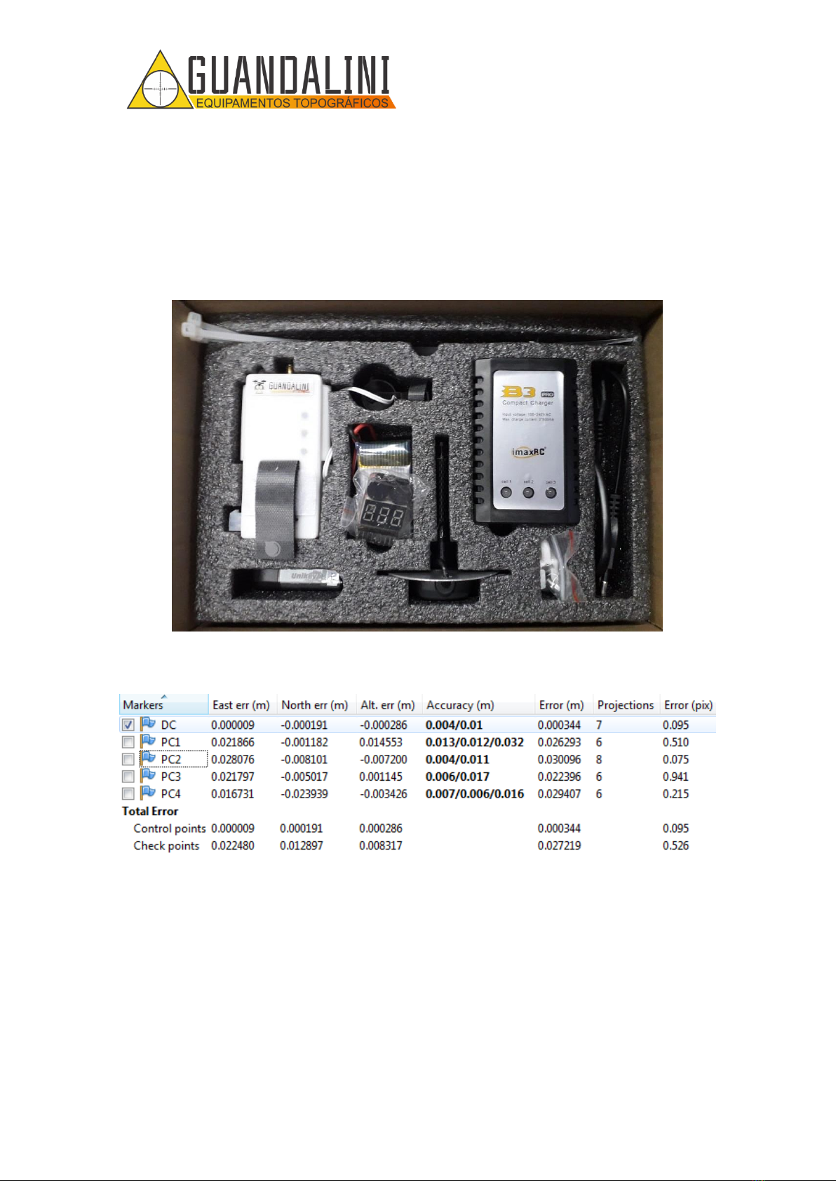
1. KIT PPK
The PPK kit is developed by the engineering team at Guandalini Equipamentos
Topograficos and can be integrated into your PHANTOM 4 ADVANCED or PRO. The kit
consists of the Reach M + card, an adapted GNSS antenna and the Guandalini PPK
software (Figure 1Figure 1).
Figure 1 - Guandalini PPK Kit
In Figure 2, observe the result of the flight with a height of 80m.
Figure 2 - Mean error obtained
Mean error: 2,7cm

MANUAL DE MONTAGEM KIT PPK NO
DJI PHANTOM 4 ADV/PRO
3
Av. Paulo VI, 1952 (novo n 184) • Sumaré • CEP 01262-010 • São Paulo • SP
(11) 4800-3157 • www.guandalinibr.com
2. ASSEMBLING THE KIT PPK ON PHANTOM 4 ADV/PRO
2.1. DRONE MOUNTING
2.1.1. STEP 1
With the KIT PPK GUANDALINI in hands, remove the control module from the foam
cradle, shown in Figure 3.
Figure 3 - Control Module Guandalini PPK
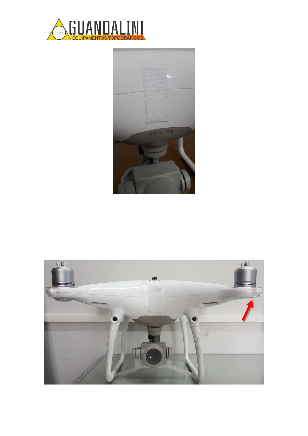
2.1.2. STEP 2
Remove the velcro that is attached to the control module (Figure 4), peel off the
protective layer of glue from it and place it in the center of the front position of the
Phantom 4 ADV / PRO, that is, on the face where the camera faces you, as shown in
Figure 5.
Figure 4 - Removal of the velcro that is glued to the Phantom 4 ADV/PRO.
MANUAL DE MONTAGEM KIT PPK NO
DJI PHANTOM 4 ADV/PRO
4
Av. Paulo VI, 1952 (novo n 184) • Sumaré • CEP 01262-010 • São Paulo • SP
(11) 4800-3157 • www.guandalinibr.com
Figure 5 - Positioning the Velcro on the Phantom 4 ADV/PRO.
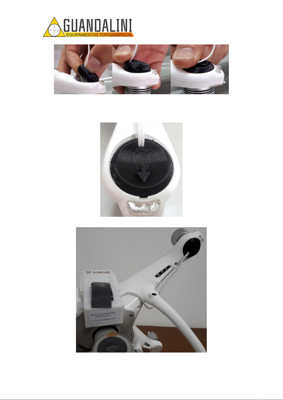
2.1.3. STEP 3
Remove the protective cover from the original LED on the right front side (looking in
front of the drone –Figure 6) with a small screwdriver, using a small opening in the
protector (Figure 7).
Figure 6 - Indication for removing the Phantom 4 ADV/PRO LED protector..

MANUAL DE MONTAGEM KIT PPK NO
DJI PHANTOM 4 ADV/PRO
5
Av. Paulo VI, 1952 (novo n 184) • Sumaré • CEP 01262-010 • São Paulo • SP
(11) 4800-3157 • www.guandalinibr.com
Figure 7 - Indication of the opening in the led protector. B) Screwdriver for removing the Phantom 4
ADV/PRO protector. C) Protector removed
2.1.4. STEP 4
Pass the cable behind the leg and insert the new LED protector in the space for it,
directing the arrow out of the drone (Figure 8), in Figure 9 the sequence for placing the
new protector is shown.
Figure 8 - Positioning of the LED protector for PHANTOM 4 ADV/PRO.
OPENING IN THE
LED PROTECTOR.
ATTENTION TO
THE DIRECTION
OF THE ARROW
A
B
C
MANUAL DE MONTAGEM KIT PPK NO
DJI PHANTOM 4 ADV/PRO
6
Av. Paulo VI, 1952 (novo n 184) • Sumaré • CEP 01262-010 • São Paulo • SP
(11) 4800-3157 • www.guandalinibr.com
Figure 9 - A) Position to place the protector. B) Where to press the new protector. C) How it should look.
Figure 10 and Figure 11 show what the protector should look like on the Phantom 4
ADV/PRO after installation.
Figure 10 - Installation of the LED protector completed..
Figure 11 - Partial assembly of the GUANDALINI PPK KIT for Phantom 4 ADV/PRO.
A
B
C

MANUAL DE MONTAGEM KIT PPK NO
DJI PHANTOM 4 ADV/PRO
7
Av. Paulo VI, 1952 (novo n 184) • Sumaré • CEP 01262-010 • São Paulo • SP
(11) 4800-3157 • www.guandalinibr.com
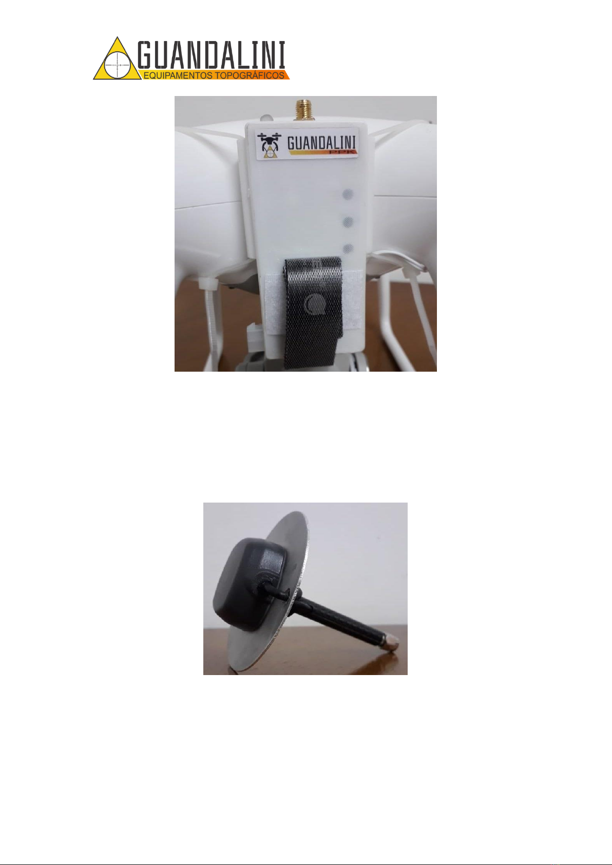
2.1.5. STEP 5
Position the control module in the center of the drone, aligning the marking that exists
on the control module with the line of the central axis of the drone, as shown in Figure
12 and Figure 13. Soon after, 1 nylon clamp should be inserted (Figure 14) in each arm
of the control module (Figure 15) and wrap it around the drone arm. When wrapping,
be sure to tighten the tapes together so that the control module is in the center, as
shown in Figure 16.
Attention!
Tighten the nylon clamp just enough so that the kit does not move. If too tight, it can break.
Figure 12 - Marking for alignment of the control module with the drone.
Figure 13 - Correct positioning of the control module in relation to the drone.

MANUAL DE MONTAGEM KIT PPK NO
DJI PHANTOM 4 ADV/PRO
8
Av. Paulo VI, 1952 (novo n 184) • Sumaré • CEP 01262-010 • São Paulo • SP
(11) 4800-3157 • www.guandalinibr.com
Figure 14 - Nylon clamp.
Figure 15 - Insertion of the nylon tape on the arm of the control module.
MANUAL DE MONTAGEM KIT PPK NO
DJI PHANTOM 4 ADV/PRO
9
Av. Paulo VI, 1952 (novo n 184) • Sumaré • CEP 01262-010 • São Paulo • SP
(11) 4800-3157 • www.guandalinibr.com
Figure 16 - Nylon tapes installed.
2.1.6. STEP 6
Remove the antenna (Figure 17) from the foam cradle and screw it onto the connector
found on the control module (Figure 18). Make sure the antenna is secure and
connected as shown in Figure 19.
Figure 17 - Antenna Tallysman.
Questo manuale è adatto per i seguenti modelli
1
Indice
Altri manuali GUANDALINI Quadricottero


