H3C WA530 Manuale utente

i
Contents
Preparing for installation ····································································1
Safety recommendations ·············································································································1
Temperature and humidity requirements ·························································································1
Installation accessories ···············································································································1
Installation tools·························································································································2
Installing the AP···············································································3
Installation flowchart ···················································································································3
Pre-installation tasks···················································································································3
Determining the installation position ·······························································································3
Installing the AP ························································································································4
Mounting the AP on a wall·····································································································4
Mounting the AP on a ceiling ·································································································7
Connecting the AP to the power source ··························································································8
Check before power-on ········································································································8
Connecting the PoE power supply ··························································································8
Connecting the local power supply ··························································································9
PoE injector power supply ·····································································································9
Check after power-on ········································································································· 10
Connecting the AP to the network································································································ 10
Accessing the cloud AP ··································································· 12
Accessing the cloud AP from the Web interface·············································································· 12
Accessing the cloud AP from the Oasis platform············································································· 12
Appendix A Technical specifications···················································14
Appendix B Ports and LEDs ·····························································15
Ports ····································································································································· 15
LEDs····································································································································· 16

1
Preparing for installation
Safety recommendations
WARNING!
Only qualified personnel can install and remove the AP and its accessories. You must read all
safety instructions before installation and operation.
To avoid possible bodily injury and equipment damage, read the following safety recommendations
before installing the AP. Note that the recommendations do not cover every possible hazardous
condition.
•Take adequate safety measures to avoid body injury and device damage.
•Place the AP in a dry and flat location and take anti-slip measures.
•Keep the AP clean and dust-free.
•Do not place the AP in a moist area and avoid liquid intrusion.
•Keep the AP and installation tools away from walkways.
Temperature and humidity requirements
Table 1 Temperature and humidity requirements
Item Specification
Operating temperature 0°C to 45°C (32°F to 113°F)
Storage temperature –40°C to +70°C (–40°F to +158°F)
Operating humidity 5% RH to 95% RH, noncondensing
Installation accessories
Figure 1 Accessories provided with the AP
2
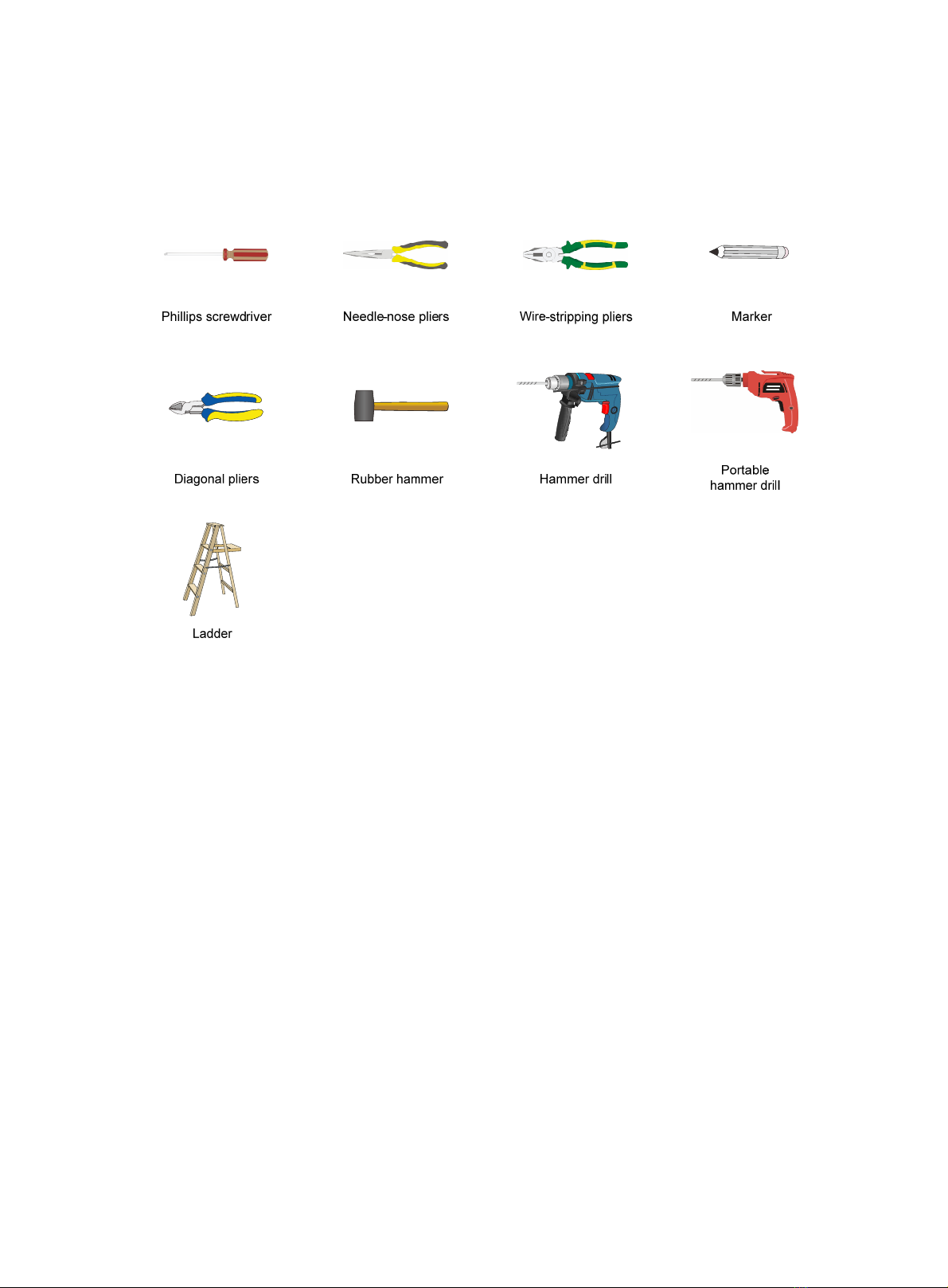
Installation tools
When installing the AP, you might need the following tools. Prepare the installation tools as
required.
Figure 2 Installation tools

3
Installing the AP
Installation flowchart
Figure 3 Installation flowchart
Pre-installation tasks
Before installing the AP, perform the following tasks:
•Connect the AP to a power source and the network. Examine the LEDs to verify that the AP
operates correctly. For information about AP LEDs, see "LEDs."
•Record the MAC address and serial number at the rear of the AP for future use.
•Make sure you have completed cabling at the installation site.
Determining the installation position
Determine the installation position by observing the following principles:
•Few obstacles such as wall exist between the AP and clients.
•The AP is far away from electronic devices (such as microwave oven) that might generate
radio frequency (RF) noise.
•The AP does not hinder people’s daily work and life.
•The place is not water seeping, water soaking, and condensing.
Determine the
installation method Mount the wall/ceiling
bracket to a wall
Mount the wall/ceiling
bracket to a ceiling tile
Install the AP
Connect the power cord
Start
Connect the AP to the
network
Pre-installation tasks
Ceil-mount Wall-mount
End

4
Installing the AP
The AP can be installed only indoors. You can mount the AP on a wall or a ceiling. The installation
procedure is the same.
The mounting bracket kit for the AP includes an AP bracket and a wall/ceiling bracket. To install the
AP on a wall or ceiling, attach the AP bracket to the AP and the wall/ceiling bracket to the wall or
ceiling.
Figure 4 Mounting bracket kit
(1) AP bracket (2) Alignment peg
(3) Wall/Ceiling bracket (4) Installation hole
Figure 5 Wall/Ceiling bracket installation holes
Mounting the AP on a wall
1. Set the alignment pegs on the AP bracket into the alignment holes in the AP rear. Use the M4
× 7 screw to secure the AP bracket to the AP through the installation hole in the middle of the
AP bracket.

5
Figure 6 Attaching the AP bracket to the AP rear
2. Mark the installation holes on the wall by using the wall/ceiling bracket, as shown in Figure 7.
Figure 7 Marking installation holes on the wall
3. Drill holes with a diameter of 6 mm (0.24 in) and a depth of 30 mm (1.18 in) in the marked
locations, as shown in Figure 8.
Figure 8 Drilling holes in the wall
4. Insert a screw anchor into each hole, and tap the screw anchor with a rubber hammer until it is
all flush with the wall surface, as shown in Figure 9.

6
Figure 9 Hammering the anchor
5. Align the installation holes in the wall/ceiling bracket with the anchors and insert screws
through the installation holes into the screw anchors. Adjust the position of the wall/ceiling
bracket and fasten the screws.
Figure 10 Attaching the wall/ceiling bracket to the wall
6. Align the two tabs on the AP bracket into the notches on the wall/ceiling bracket, and then
rotate the AP clockwise until it snaps into place, as shown in Figure 11.
Figure 11 Attaching the AP to the wall/ceiling bracket

7
Mounting the AP on a ceiling
CAUTION:
The ceiling for installing the AP must be less than 18 mm (0.71 in) in thickness, and can bear a load
of 5 kg (11.02 lb). If the ceiling is not strong enough, use boards to reinforce the ceiling as a best
practice.
To mount the AP on a ceiling:
1. Set the alignment pegs on the AP bracket into the alignment holes in the AP rear. Use the M4
× 7 screw to secure the AP bracket to the AP through the installation hole in the middle of the
AP bracket.
2. Mark the installation holes on the ceiling by using the wall/ceiling bracket.
3. Drill two holes with a diameter of 5 mm (0.20 in) in the marked positions, as shown in Figure
12.
Figure 12 Drilling holes in the ceiling
4. Thread the pan-head screws through the installation holes in the wall/ceiling bracket and into
holes in the ceiling. Fasten washers and nuts at the other side of the ceiling to attach the
wall/ceiling bracket to the ceiling, as shown in Figure 13.
Figure 13 Attaching the wall/ceiling bracket to the ceiling

8
5. Align the AP with the wall/ceiling bracket and rotate the AP clockwise until it snaps into place,
as shown in Figure 14. For more information, see "Mounting the AP on a wall."
Figure 14 Attaching the AP to the wall/ceiling bracket
6. Verify that the AP is securely installed to prevent it from falling off.
Connecting the AP to the power source
The AP supports 802.3af- and 802.3at-compliant PoE and local power supply.
Check before power-on
Check the following items before powering on the AP:
•To power the AP with local power, make sure the local power supply is reliably grounded.
•To power the AP through PoE, make sure the PoE power supply (PSE) is reliably grounded.
•To power the AP through PoE injector, make sure the PoE power supply (PSE) is reliably
grounded.
•AP is to be connected only to PoE networks without routing to the outside plant.
Connecting the PoE power supply
CAUTION:
To use both Ethernet ports on the AP, connect an Ethernet cable to one port for PoE connection
first, and then connect the other after the AP is powered on.
Use an Ethernet cable to connect the Ethernet port on the AP to a port on a switch that supports
PoE.

9
Figure 15 Connecting the PoE power supply
Connecting the local power supply
The Power adapter must be ordered separately.
Table 2 Power adapter specifications
Item Specification
Input 100 VAC to 240 VAC
Output +54 VDC at 0.74 A
You can power the AP by using an power adapter. Use the power adapter to connect the power port
of the AP to the local power source.
Connect the power adapter to the AP as shown in Figure 16.
Figure 16 Connecting the local power supply
PoE injector power supply
CAUTION:
A PoE injector must be used together with an LPS-compliant adapter provided by H3C.
The PoE injector must be ordered separately.
Connect the PoE injector to the AP and a switch with Ethernet cable. Use the power adapter to
connect the power port of the PoE injector to the local power source.
Connect the PoE injector as shown in Figure 17
Altri manuali per WA530
2
Indice
Altri manuali H3C Punto di accesso wireless

H3C
H3C WA6528X-E Manuale utente

H3C
H3C WA5320 Manuale utente

H3C
H3C WA6120H Manuale utente

H3C
H3C WA2620-AGN Manuale utente

H3C
H3C WA6330 Manuale utente

H3C
H3C WA2620X-AGNP Manuale utente

H3C
H3C WA3610i-GN Manuale utente

H3C
H3C WA5530i Manuale utente

H3C
H3C WA4320i-ACN Manuale utente

H3C
H3C WA6620X Manuale utente

H3C
H3C WA6520 Manuale utente

H3C
H3C WA4320H-ACN Guida utente

H3C
H3C WA6628E-T Manuale utente

H3C
H3C WA6500 Series Guida utente

H3C
H3C WA6120X Manuale utente

H3C
H3C WA6628 Manuale utente

H3C
H3C WA2620X-AGNP Manuale utente

H3C
H3C WA2210-AG_INDOORSINGLEBANDAP Manuale utente

H3C
H3C WA2200 Series Manuale utente

H3C
H3C WA4320X Manuale utente


 Manuale utente")
