Harbor Freight Tools Predator 63966 Manuale utente

!"#$%&'&%($()'*+)&#$,++)"&-./&
0122&34!&1/&51/!6789
:($()'*+)&(;<'="*&>+$*'#$"&
>')?+$&@+$+;#,(9&&6<#"&#"&'&A+#"+$&
B+=&>'$$+*&"((&+)&"@(CC9
/7D7E&="(&#$"#,(&
'&<+@(&+)&%')'%(F&
7D7/&1G&,++)"&'$,&
H#$,+H"&')(&+A($9
4$CB&="(&4!681I7&
'$,&J')&'H'B&J)+@&
H#$,+H"F&,++)"F&
'$,&K($*"9 D#"#*&+=)&H(?"#*(&'*L&<**ALMMHHH9<')?+)J)(#%<*9>+@
7@'#C&+=)&*(><$#>'C&"=AA+)*&'*L&A)+,=>*"=AA+)*N<')?+)J)(#%<*9>+@
7@'#C&+=)&($%#$(&"=AA+)*&'*L&A)(,'*+)N<')?+)J)(#%<*9>+@
ITEM:
63966
301
cc
GASOLINE ENGINE
Owner’s Manual & Safety Instructions
Save This Manual&Keep this manual for the safety warnings and precautions, assembly,
operating, inspection, maintenance and cleaning procedures. Write the product’s serial number in the
back of the manual near the assembly diagram (or month and year of purchase if product has no number).
Keep this manual and the receipt in a safe and dry place for future reference. 18a
!"#$%&'&%($()'*+)&#$,++)"&-./&
0122&34!&1/&51/!6789
:($()'*+)&(;<'="*&>+$*'#$"&
>')?+$&@+$+;#,(9&&6<#"&#"&'&A+#"+$&
B+=&>'$$+*&"((&+)&"@(CC9
/7D7E&="(&#$"#,(&
'&<+@(&+)&%')'%(F&
7D7/&1G&,++)"&'$,&
H#$,+H"&')(&+A($9
4$CB&="(&4!681I7&
'$,&J')&'H'B&J)+@&
H#$,+H"F&,++)"F&
'$,&K($*"9
When unpacking, make sure that the product is intact
and undamaged. If any parts are missing or broken,
please call 1-888-866-5797 as soon as possible.
Copyright© 2018 by Harbor Freight Tools®. All rights reserved.
No portion of this manual or any artwork contained herein may be reproduced in
any shape or form without the express written consent of Harbor Freight Tools.
Diagrams within this manual may not be drawn proportionally. Due to continuing
improvements, actual product may differ slightly from the product described herein.
Tools required for assembly a nd service may not be in cl ud ed .
E(',&*<#"&@'*()#'C&?(J+)(&="#$%&*<#"&A)+,=>*9&
G'#C=)(&*+&,+&"+&>'$&)("=C*&#$&"()#+="&#$O=)B9&
8.D7&6P18&5./!.29

Page 2 G+)&*(><$#>'C&Q=("*#+$"F&AC('"(&>'CC&RSTTTSTUUSVWXW9 ITEM 63966
8.G763 876!Y 4Y7E.614/ 5.1/67/./-7
6'?C(&+J&-+$*($*"
Safety ......................................................... 2
Setup .......................................................... 6
Specifications ............................................. 6
Operation ................................................... 10
Maintenance .............................................. 16
Parts List and Diagram .............................. 22
Warranty .................................................... 24
Z.E/1/:&835[428&./I&I7G1/1614/8
This is the safety alert symbol. It is used to alert you to potential
personal injury hazards. Obey all safety messages that
follow this symbol to avoid possible injury or death.
Indicates a hazardous situation which, if not avoided,
will result in death or serious injury.
Indicates a hazardous situation which, if not avoided,
could result in death or serious injury.
Indicates a hazardous situation which, if not avoided,
could result in minor or moderate injury.
Addresses practices not related to personal injury.
15Y4E6./6&8.G763&1/86E!-614/8
8.D7&6P787&1/86E!-614/8
This manual contains important instructions that should be followed during
installation and maintenance of the Generator and any batteries.
8(*&=A&Y)(>'=*#+$"
1. This unit is to be installed so that access is
restricted to only qualified service personnel
who have been instructed of the reasons for the
restrictions applied to the location and about any
precautions that must be taken. Access shall be
through the use of a special tool, or lock and key,
or other means of security and shall be controlled
by the authority responsible for the location.
2. Gasoline fuel and fumes are flammable, and
potentially explosive. Use proper fuel storage
and handling procedures. Do not store fuel
or other flammable materials nearby.
3. Have multiple ABC class fire extinguishers nearby.
4. Operation of this equipment may create sparks that
can start fires around dry vegetation.
A spark arrestor may be required. The operator
should contact local fire agencies for laws or
regulations relating to fire prevention requirements.
5. Set up and use only on a flat, level,
well-ventilated surface.
6. All connections and conduits from the Generator
to the load must only be installed by trained and
licensed electricians, and in compliance with all
relevant local, state, and federal electrical codes and
standards, and other regulations where applicable.
7. Connections for standby power to a building
electrical system must be made by a qualified
electrician. The connection must isolate the
Generator power from utility power, and must
comply with all applicable laws and electrical codes.
8. Wear ANSI-approved safety goggles, heavy-duty
work gloves, and dust mask/respirator during set up.
9. Use only lubricants and fuel
recommended in this manual.

Page 3G+)&*(><$#>'C&Q=("*#+$"F&AC('"(&>'CC&RSTTTSTUUSVWXW9ITEM 63966
8.G763876!Y4Y7E.614/5.1/67/./-7
10. Improper connections to a building electrical system
can allow electrical current from the Generator
to backfeed into the utility lines. Such backfeed
may electrocute utility company workers or others
who contact the lines during a power outage, and
the Generator may explode, burn, or cause fires
when utility power is restored. Consult the utility
company and a qualified electrician if intending
to use the Generator for back up power.
11. Do not operate the Generator before grounding.
The Generator must be earth-grounded
in accordance with all relevant electrical
codes and standards before operation.
4A()'*#$%&Y)(>'=*#+$"
1. -.E[4/&54/4\1I7&P.].EI&
!"#$%&'&%($()'*+)&#$,++)"&-./&0122&
34!&1/&51/!6789&
Generator exhaust contains carbon
monoxide. This is a poison you cannot
see or smell.
NEVER use inside a home or garage,
EVEN IF doors and windows are open.
Only use OUTSIDE and far away from windows,
doors, and vents.
2. Never use a generator indoors, including in
garages, basements, crawlspaces and sheds.
Opening doors and windows or using fans will NOT
prevent carbon monoxide build up in the home.
3. When using generators, keep them outdoors
and far away from open doors, windows,
and vents to avoid toxic levels of carbon
monoxide from building up indoors.
4. If you start to feel sick, dizzy, or weak while
using a generator, get to fresh air right away.
The carbon monoxide from generators can
quickly lead to full incapacitation and death.
5. Keep children away from the equipment,
especially while it is operating.
6. Keep all spectators at least six feet
from the Engine during operation.
7. Do not touch engine during use.
Let engine cool down after use.
8. Never store fuel or other flammable
materials near the engine.
9. Fire Hazard! Do not fill gas tank while engine is
running. Do not operate if gasoline has been spilled.
Clean spilled gasoline before starting engine.
Do not operate near pilot light or open flame.
10. If the plugged-in product operates abnormally
or unusually slow, immediately stop using the
Generator as a power source. Always read and
adhere to the instruction manual of the product
to be powered, to make sure that it can be safely
and efficiently powered by a portable generator.
11. Before connecting an appliance or power cord
to the Generator: Make sure that it is in good
working order. Faulty appliances or power cords
can create a potential for electrical shock.
12. Do not exceed the maximum power rating of the
Generator. Make sure that the total electrical rating
of the all of the tools or appliances plugged into
the Generator at the same time does not exceed
that of the Generator. Check that the startup
surge will not be beyond the limit of the Generator.
Power levels between rated and maximum
may be used for no more than 30 minutes.
13. Avoid substantially overloading which will
trip the circuit breaker. Exceeding the time
limit for maximum power operation or slightly
overloading the Generator may not switch the
circuit breaker or circuit protector OFF, but will
shorten the service life of the Generator.
14. Do not attempt to connect or disconnect
load connections while standing in
water, or on wet or soggy ground.
15. Do not touch electrically energized parts of
the Generator and interconnecting cables
or conductors with any part of the body, or
with any non-insulated conductive object.
16. Connect the Generator only to a load or
electrical system (120 volt or 240 volt) that is
compatible with the electrical characteristics
and rated capacities of the Generator.
8(*&=A&Y)(>'=*#+$"&^>+$*#$=(,_

Page 4 G+)&*(><$#>'C&Q=("*#+$"F&AC('"(&>'CC&RSTTTSTUUSVWXW9 ITEM 63966
8.G763 876!Y 4Y7E.614/ 5.1/67/./-7
17. :G-1&YE7-.!614/8&
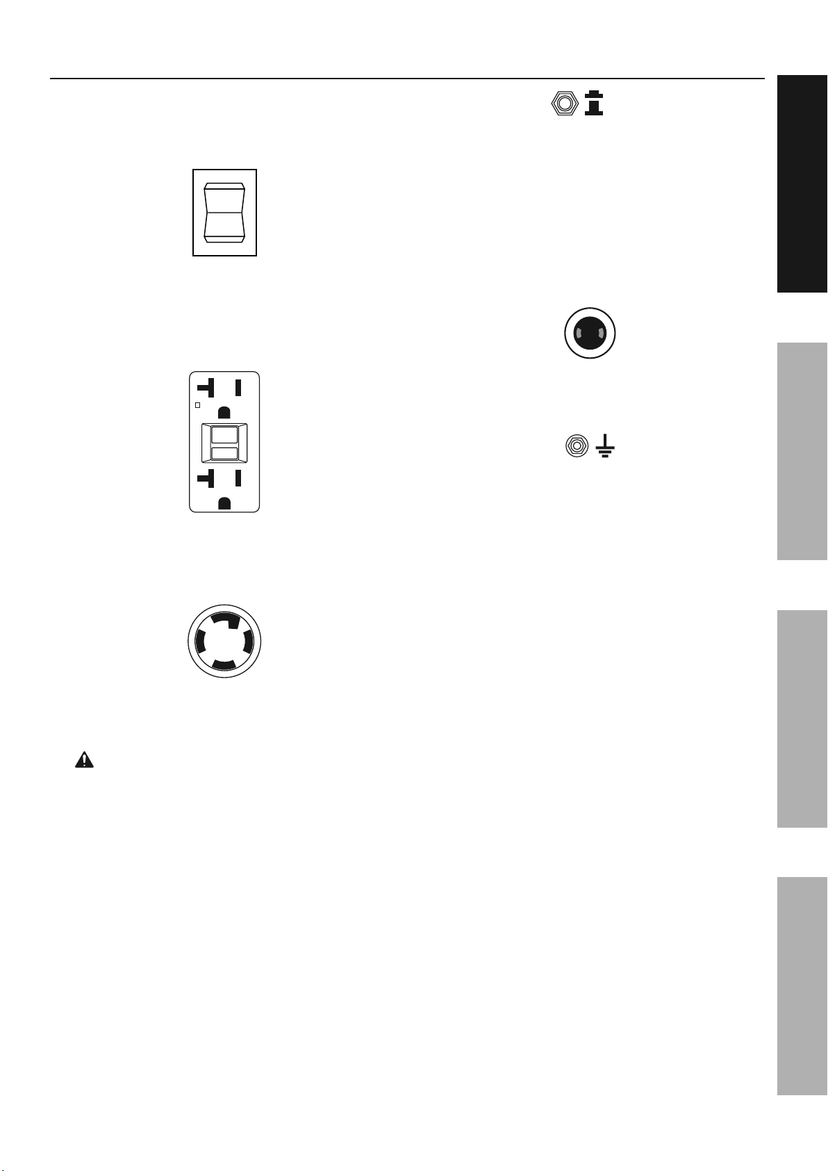
Test Ground Fault Circuit Interrupter (GFCI)
receptacles before each use as follows:
a. Disconnect all devices from the Generator.
b. Start the engine.
c. Press Test button on receptacle
to trip the GFCI device.
d. The Reset button should extend, cutting
off electricity to the receptacle.
e. If above test fails, do not use receptacle
until it is repaired or replaced.
f. Press Reset button in for use.
:G-1&)(>(A*'>C("&H#CC&$+*&A)+*(>*&'%'#$"*&
(C(>*)#>&"<+>`&#J&:($()'*+)&#"&$+*&%)+=$,(,9&&
Refer to Grounding on page 8.
18. Insulate all connections and disconnected wires.
19. Guard against electric shock. Prevent body
contact with grounded surfaces such as
pipes, radiators, ranges, and refrigerators.
20. Only use a suitable means of transport and
lifting devices with sufficient weight bearing
capacity when transporting the Generator.
21. Secure the Generator on transport vehicles to
prevent the tool from rolling, slipping, and tilting.
22. Industrial applications must follow
OSHA requirements.
23. Do not leave the Generator unattended when it is
running. Turn off the Generator (and remove safety
keys, if available) before leaving the work area.
24. The Generator engine can produce high noise
levels. Prolonged exposure to noise levels
above 85 dBA is hazardous to hearing. Always
wear ear protection when operating or working
around the gas engine while it is operating.
25. Wear ANSI-approved safety glasses,
hearing protection, and NIOSH-approved
dust mask/respirator during use.
26. People with pacemakers should consult their
physician(s) before use. Electromagnetic fields
in close proximity to a heart pacemaker could
cause pacemaker interference or pacemaker
failure. Caution is necessary when near
the engine’s magneto or recoil starter.
27. Use only accessories that are recommended
by Harbor Freight Tools for your model.
Accessories that may be suitable for one
piece of equipment may become hazardous
when used on another piece of equipment.
28. Do not operate in explosive atmospheres,
such as in the presence of flammable
liquids, gases, or dust. Gasoline-powered
engines may ignite the dust or fumes.
29. Keep grounded conductive objects, such as
tools, away from exposed, live electrical parts
and connections to avoid sparking or arcing.
These events could ignite fumes or vapors.
30. Stay alert, watch what you are doing and
use common sense when operating this
piece of equipment. Do not use this piece
of equipment while tired or under the
influence of drugs, alcohol or medication.
31. Dress properly. Do not wear loose clothing or
jewelry. Keep hair, clothing and gloves away
from moving parts. Loose clothes, jewelry or
long hair can be caught in moving parts.
32. Parts, especially exhaust system components,
get very hot during use. Stay clear of hot parts.
33. Do not cover the Generator or its
engine during operation.
34. Keep the Generator, its engine, and
surrounding area clean at all times.
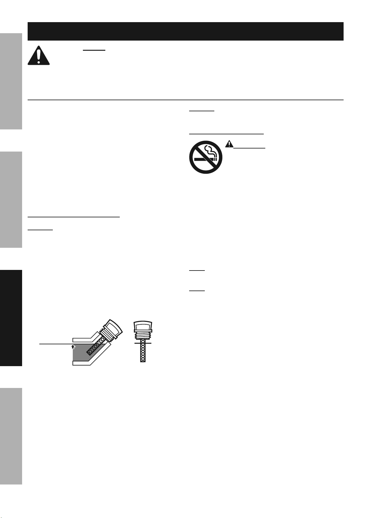
35. Do not smoke, or allow sparks, flames,
or other sources of ignition around the
equipment, especially when refuelling.
36. Use the Generator, accessories, etc., in
accordance with these instructions and in the
manner intended for the particular type of
equipment, taking into account the working
conditions and the work to be performed. Use of
the equipment for operations different from those
intended could result in a hazardous situation.
37. Do not operate the Generator with known
leaks in the engine’s fuel system.
38. When spills of fuel or oil occur, they must be
cleaned up immediately. Dispose of fluids and
cleaning materials as per any local, state, or
federal codes and regulations. Store oil rags in
a bottom-ventilated, covered, metal container.
39. Keep hands and feet away from moving parts. Do
not reach over or across Generator while operating.
40. Before use, check for misalignment or binding
of moving parts, breakage of parts, and any
other condition that may affect the Generator’s
operation. 1J&,'@'%(,F&<'K(&*<(&:($()'*+)&
"()K#>(,&?(J+)(&="#$%9 Many accidents are
caused by poorly maintained equipment.
41. Use the correct generator for the application.
Do not modify the generator or its engine,
and do not use the generator for a
purpose for which it is not intended.

Page 5G+)&*(><$#>'C&Q=("*#+$"F&AC('"(&>'CC&RSTTTSTUUSVWXW9ITEM 63966
8.G763876!Y4Y7E.614/5.1/67/./-7
8()K#>(&Y)(>'=*#+$"
1. [(J+)(&"()K#>(F&@'#$*($'$>(F&+)&>C('$#$%L
a. !$AC=%&'CC&,(K#>("&J)+@&*<(&:($()'*+)9
b. 6=)$&*<(&($%#$(&"H#*><&*+&#*"&a4GGb&A+"#*#+$9
c. .CC+H&*<(&($%#$(&*+&>+@AC(*(CB&>++C9
d. 6<($F&)(@+K(&*<(&"A')`&AC=%&
>'A&J)+@&*<(&"A')`&AC=%9
2. Keep all safety guards in place and in
proper working order. Safety guards include
muffler, air cleaner, mechanical guards,
and heat shields, among other guards.
3. Make sure the Engine Switch is in its “OFF”
position before moving the Generator and
before performing any service, maintenance,
or cleaning procedures on the unit.
4. Keep all electrical equipment clean and dry.
Replace any wiring where the insulation is
cracked, cut, abraded, or otherwise degraded.
Replace terminals that are worn, discolored, or
corroded. Keep terminals clean and tight.
5. I+&$+*&'C*()&+)&',O="*&'$B&A')*&+J&*<(&
(Q=#A@($*&+)&#*"&($%#$(&*<'*&#"&"('C(,&?B&*<(&
@'$=J'>*=)()&+)&,#"*)#?=*+)9&&4$CB&'&Q='C#J#(,&
"()K#>(&*(><$#>#'$&@'B&',O="*&A')*"&*<'*&@'B&
#$>)('"(&+)&,(>)('"(&%+K()$(,&($%#$(&"A((,9
6. Wear ANSI-approved safety goggles,
heavy-duty work gloves, and dust
mask/respirator during service.
7. Maintain labels and nameplates on
the equipment. These carry important
information. If unreadable or missing, contact
Harbor Freight Tools for a replacement.
8. Have the equipment serviced by a qualified repair
person using only identical replacement parts.
This will ensure that the safety of the equipment
is maintained. Do not attempt any service or
maintenance procedures not explained in this
manual or any procedures that you are uncertain
about your ability to perform safely or correctly.
9. Store equipment out of the reach of children.
10. Follow scheduled engine and
equipment maintenance.
:G-1&Y)+*(>*#+$L
This Generator is equipped with two 3-Prong,
duplex 120 V ground fault circuit interrupter
(GFCI) receptacles. These outlets provide
additional protection from the risk of electric
shock. Should replacement of the receptacles
become necessary, use only identical replacement
parts that include GFCI protection.
E(J=(C#$%L
1. Do not refill the fuel tank while the
engine is running or hot.
2. Do not smoke, or allow sparks, flames,
or other sources of ignition around the
equipment, especially when refuelling.
3. 64&YE7D7/6&G!72&27.0.:7&./I&G1E7&
P.].EIF&I+&$+*&+K()J#CC&H#*<&J=(C9&G#CC&H#*<&
J=(C&'>>+),#$%&*+&*<(&G=(C&2(K(C&#$J+)@'*#+$&
?(C+H&*<(&8A(>#J#>'*#+$&><')*&J+)&B+=)&@+,(C9
4. Do not fill fuel tank to the top. Leave a little
room for the fuel to expand as needed.
5. Refuel in a well-ventilated area only.
6. Wipe up any spilled fuel and allow excess
to evaporate before starting engine.
6+&A)(K($*&G1E7F&,+&$+*&"*')*&*<(&($%#$(&
H<#C(&*<(&"@(CC&+J&J=(C&<'$%"&#$&*<(&'#)9
&8.D7&6P787&1/86E!-614/89

Page 6 G+)&*(><$#>'C&Q=("*#+$"F&AC('"(&>'CC&RSTTTSTUUSVWXW9 ITEM 63966
8.G763 876!Y 4Y7E.614/ 5.1/67/./-7
G=$>*#+$'C&I(">)#A*#+$
8A(>#J#>'*#+$"
Generator
Output 120 / 240 VAC, 60 Hz
5,500 Running Watts (6,500 Max. Starting Watts)
Electrical Receptacle
Two 3-Prong, duplex NEMA #5-20 120 V GFCI
One 4-Prong, NEMA #L14-30 twistlock 120 V / 240 V
One DC Outlet 12 VDC
Engine
Displacement 301 cc
Engine Type Horizontal Single Cylinder 4 stroke OHV
Cooling System Forced air cooled
Fuel Type 87+ octane stabilizer treated unleaded gasoline
Recommended ll level 8 Gallons
Engine Oil Type SAE 10W – 30 above 32° F
5W – 30 at 32° F or below
Capacity 1.16 Quart
Spark Plug Type NHSP® / Torch® F6TC
Gap 0.028" – 0.031"
Valve Clearance Intake 0.004" – 0.006"
Exhaust 0.006" – 0.008"
Run Time @ 50% load Up to 14.5 hr.
Available accessories Wheel kit (sold separately)
The emission control system for this Generator’s Engine is warranted for standards set by the U.S. Environmental
Protection Agency. For warranty information, refer to the last pages of this manual.
-+@A+$($*"&'$,&-+$*)+C"
Fuel Cap
Frame
Starter
Handle
DC Circuit Breaker
Fuel Valve
Power Switch
AC Circuit Breakers
Choke
Low Oil Indicator
AC Receptacle
Air Filter
DC Receptacle
Ground Terminal
Wheel Kit sold separately
GFCI AC Receptacles

Page 7G+)&*(><$#>'C&Q=("*#+$"F&AC('"(&>'CC&RSTTTSTUUSVWXW9ITEM 63966
8.G763876!Y4Y7E.614/5.1/67/./-7
-+@A+$($*"&'$,&-+$*)+C"&^>+$*#$=(,_
The following are descriptions of the controls
on the power panel. Your Generator has
sockets to power your products with circuit
breakers to protect the voltage flow.
1.
1
4
86.E6
7$%#$(&8H#*><L&&Used to start and stop the Engine.
2. .-&E(>(A*'>C("L&&The Generator contains several
AC Receptacles to power tools and equipment.
a.
E7876
6786
E7876
6786
cSY)+$%F&,=AC(;&&
Rde&K+C*&:G-1&)(>(A*'>C(&&
^/75.&fVSde_&
b. gSY)+$%F&*H#"*C+>`F&&
RdeMdge&K+C*&)(>(A*'>C(&
^/75.&f2RgSce_
Z.E/1/:h&&Connect tools and equipment
only to the Receptacle (120 volt or 240 volt)
that is compatible with the electrical
characteristics and rated capacities of
the tools and equipment being used.
3.
4/
4GG
-#)>=#*&[)('`()"L&The circuit breaker protects
the Generator from overloading. The rating of the
breaker and the load it protects are marked near
the breaker. Should any of the Circuit Breakers trip,
the Generator will stop the electricity output. If this
happens, unplug all loads from the Generator.
Allow the Generator to cool down. Then, press
the tripped Circuit Breaker, restart the Engine, and
re-attach loads.
4. Rd&DI-&E(>(A*'>C(L&12 VDC Receptacle provides
a power source for 12 volt DC items.
5. :)+=$,#$%&6()@#$'CL&&Prior to each use, set
up the ground wire (not included) connection to
the Grounding Terminal to properly ground the
Generator. Refer to Grounding on page 8
for instructions on grounding the Generator.

Page 8 G+)&*(><$#>'C&Q=("*#+$"F&AC('"(&>'CC&RSTTTSTUUSVWXW9 ITEM 63966
8.G763 876!Y 4Y7E.614/ 5.1/67/./-7
1$#*#'C&6++C&8(*&!AM.""(@?CB
& E(',&*<(&7/61E7&15Y4E6./6&8.G763&1/G4E5.614/&"(>*#+$&'*&*<(&?(%#$$#$%&+J&*<#"&
@'$='C&#$>C=,#$%&'CC&*(;*&=$,()&"=?<(',#$%"&*<()(#$&?(J+)(&"(*&=A&+)&="(&+J&*<#"&A)+,=>*9
64&YE7D7/6&87E14!8&1/i!E3L&
4A()'*(&+$CB&H#*<&A)+A()&"A')`&'))("*+)&#$"*'CC(,9
4A()'*#+$&+J&*<#"&(Q=#A@($*&@'B&>)('*(&"A')`"&*<'*&>'$&"*')*&J#)("&')+=$,&,)B&K(%(*'*#+$9&
.&"A')`&'))("*+)&@'B&?(&)(Q=#)(,9&6<(&+A()'*+)&"<+=C,&>+$*'>*&C+>'C&J#)(&'%($>#("&
J+)&C'H"&+)&)(%=C'*#+$"&)(C'*#$%&*+&J#)(&A)(K($*#+$&)(Q=#)(@($*"9
At high altitudes, the engine’s carburetor, governor, and any other parts that control the fuel-
air ratio will need to be adjusted by a qualified mechanic to allow efficient high-altitude use
and to prevent damage to the engine and any other devices used with this product.
/+*(L For additional information regarding the parts listed in the following pages,
refer to the Assembly Diagram near the end of this manual.
:)+=$,#$%
The Generator must be properly grounded before use. Have the unit grounded
by a qualified electrician if you are not qualified to do so.
To ground the Generator, connect a #6 AWG grounding wire (not included) from the
Grounding Terminal on the Control Panel to a grounding rod (not included) that has been
driven at least 24 inches deep into the earth. The grounding rod must be an earth-driven
copper or brass rod (electrode) which can adequately ground the Generator.
There is a permanent conductor between the portable generator stator winding and the frame.
Z.E/1/:h :G-1&)(>(A*'>C("&H#CC&$+*&A)+*(>*&J)+@&(C(>*)#>&"<+>`&#J&:($()'*+)&#"&$+*&%)+=$,(,9
/461-7L This Generator is not intended to power sensitive electronic equipment without the addition of an
appropriate line conditioner and surge protector (both not included). 8($"#*#K(&(C(>*)+$#>&(Q=#A@($*&#$>C=,("F&
?=*&#"&$+*&C#@#*(,&*+F&'=,#+MK#,(+&(Q=#A@($*F&"+@(&*(C(K#"#+$&"(*"F&>+@A=*()"F&'$,&A)#$*()"9&&Sensitive
electronic equipment should be operated on approved inverter-type generators or pure sine wave generators.
/+*(L Wheel Kit, #68531 (sold separately) can be used with this Generator.

Page 9G+)&*(><$#>'C&Q=("*#+$"F&AC('"(&>'CC&RSTTTSTUUSVWXW9ITEM 63966
8.G763876!Y4Y7E.614/5.1/67/./-7
P#%<&.C*#*=,(&4A()'*#+$&.?+K(&ceee&J((*
Z.E/1/:h 64&YE7D7/6&87E14!8&1/i!E3&GE45&G1E7L
Follow instructions in a well-ventilated area away from ignition sources.
If the engine is hot from use, shut the engine off and wait for it to cool before proceeding. Do not smoke.
/461-7L Warranty void if necessary adjustments are not made for high altitude use.
At high altitudes, the engine’s carburetor, governor, and any other parts that control the fuel-air ratio will need
to be adjusted by a qualified mechanic to allow efficient high-altitude use and to prevent damage to the engine
and any other devices used with this product. The fuel system on this engine may be influenced by operation
at higher altitudes. Proper operation can be ensured by installing an altitude kit at altitudes higher than 3000 ft.
above sea level. At elevations above 8000 ft, the engine may experience decreased performance, even with
the proper main jet. Operating this engine without the proper altitude kit installed may increase the engine’s
emissions and decrease fuel economy and performance. The kit should be installed by a qualified mechanic.
1. Turn off the engine.
2. Close the fuel valve.
3.
Move the air cleaner housing aside to allow access to the carburetor:
a. Loosen the knob and remove air cleaner cover.
b. Remove the foam filter and deflecting plate.
c. Remove the nuts to allow the air cleaner housing
to be moved aside.
4. Place a bowl under the fuel cup to catch any spilled fuel.
5. Unthread the screws holding the solenoid in place.
-.!614/h Carburetor bowl may have gas in it which
will leak upon removing the solenoid/bolt.
6. Disconnect the solenoid and solenoid seal from the bolt.
7. Unthread the bolt holding the fuel cup.
8. Remove the bolt, Bolt Seal, fuel cup, Fuel Cup Seal and Main Jet from the body of the carburetor assembly.
A carburetor screwdriver (not included) is needed to remove and install the Main Jet.
/+*(L The mixing tube is held in place by the Main Jet and
might fall out when it is removed. If it falls out, replace it in
the same orientation before replacing the Main Jet.
9. Replace the Main Jet with the replacement Main Jet
needed for your altitude range (part 1a or 2a).
/+*(L The Fuel Cup Seal and Bolt Seal may be damaged during
removal and should be replaced with the new ones from the kit.
10. Replace the Fuel Cup Seal (4a), fuel cup,
Bolt Seal (3a), and bolt. Tighten in place.
/461-7L Do not cross thread bolt when tightening.
Finger tighten first and then use a wrench to
make sure the bolt is properly threaded.
11. Replace the solenoid and Solenoid Seal (5a),
and tighten in place with screws.
12. Reassemble the air cleaner and reattach all hoses to it.
13. Wipe up any spilled fuel and allow excess to evaporate
before starting engine. To prevent FIRE, do not start
the engine while the smell of fuel hangs in the air.
P#%<&.C*#*=,(&0#*&Y')*"&2#"*&S&.
Y')* I(">)#A*#+$ j*B
1a Main Jet 3000-6000 ft. 1
2a Main Jet 6000-8000 ft. 1
3a Bolt Seal 1
4a Fuel Cup Seal 1
5a Solenoid Seal 1
.#)&-C('$()&
P+="#$%
/=*"
I(JC(>*#$%&YC'*(
G+'@&G#C*()
.#)&
-C('$()&
-+K()
-')?=)(*+)&
.""(@?CB
5'#$&i(*
G=(C&-=A&8('C
5#;#$%&6=?(
^@#%<*&)(@'#$&
#$"#,(&>')?=)(*+)_
G=(C&-=A
[+C*&8('C
[+C*
8+C($+#,
8+C($+#,&8('C
8>)(H"

Page 10 G+)&*(><$#>'C&Q=("*#+$"F&AC('"(&>'CC&RSTTTSTUUSVWXW9 ITEM 63966
8.G763 876!Y 4Y7E.614/ 5.1/67/./-7
4A()'*#$%&1$"*)=>*#+$"
& E(',&*<(&7/61E7&15Y4E6./6&8.G763&1/G4E5.614/&"(>*#+$&'*&*<(&?(%#$$#$%&+J&*<#"&
@'$='C&#$>C=,#$%&'CC&*(;*&=$,()&"=?<(',#$%"&*<()(#$&?(J+)(&"(*&=A&+)&="(&+J&*<#"&A)+,=>*9
1$"A(>*&*++C&?(J+)(&="(F&C++`#$%&J+)&,'@'%(,F&C++"(F&'$,&@#""#$%&A')*"9&&
1J&'$B&A)+?C(@"&')(&J+=$,F&,+&$+*&="(&*++C&=$*#C&)(A'#)(,9
:($()'*+)&Y)(S8*')*&-<(>`"
1. Inspect engine and equipment, looking for
damaged, loose, and missing parts before set
up and starting. If any problems are found,
do not use equipment until fixed properly.
2. Brush off outside of Engine.
3. Remove the air filter cover and the air
filter elements and check for dirt. Clean
as needed and replace them.
4. Install carbon monoxide alarm(s) with battery
backup in all nearby buildings according
to alarm manufacturer′s instructions.
-<(>`#$%&'$,&G#CC#$%&7$%#$(&4#C
/461-7L&&3+=)&Z'))'$*B&#"&D41I&#J&*<(&($%#$(k"&
>)'$`>'"(&#"&$+*&A)+A()CB&J#CC(,&H#*<&+#C&?(J+)(&
('><&="(9&&[(J+)(&('><&="(F&><(>`&*<(&+#C&C(K(C9&&
7$%#$(&H#CC&$+*&"*')*&H#*<&C+H&+)&$+&($%#$(&+#C9
1. Make sure the engine is stopped and is level.
2. Close the Fuel Valve.
3. Clean the top of the Dipstick and the
area around it. Remove the Dipstick
by threading it counterclockwise, and
wipe it off with a clean lint free rag.
Full level
Full level
4. Reinsert the Dipstick without threading it in and
remove it to check the oil level. The oil level
should be up to the full level as shown above.
5. If the oil level is at or below the low mark add the
appropriate type of oil until the oil level is at the
proper level. SAE 10W-30 oil is recommended
for general use. (The SAE Viscosity Grade chart
on page 17 in the Service section shows other
viscosities to use in different average temperatures.)
6. Thread the dipstick back in clockwise.
/461-7L&&I+&$+*&)=$&*<(&($%#$(&H#*<&*++&C#**C(&+#C9&&
7$%#$(&H#CC&"<=*&+JJ&#J&($%#$(&+#C&C(K(C&#"&*++&C+H9
-<(>`#$%&'$,&G#CC#$%&G=(C
Z.E/1/:h 64&YE7D7/6&87E14!8&
1/i!E3&GE45&G1E7L
Fill the fuel tank in a well-ventilated area
away from ignition sources. If the engine is
hot from use, shut the engine off and wait
for it to cool before adding fuel.
Do not smoke.
1. Clean the Fuel Cap and the area around it.
2. Unscrew and remove the Fuel Cap.
3. If needed, fill the Fuel Tank to about 1 inch
under the fill neck with 87 octane or higher
unleaded gasoline that has been treated with
a fuel stabilizer additive. Follow fuel stabilizer
manufacturer’s recommendations for use.
/+*(L&&I+&$+*&="(&%'"+C#$(&>+$*'#$#$%&@+)(&*<'$&
Rel&(*<'$+C&^7Re_9&&I+&$+*&="(&7TV&(*<'$+C9
/+*(L&&I+&$+*&="(&%'"+C#$(&*<'*&<'"&?(($&"*+)(,&#$&'&
@(*'C&J=(C&>+$*'#$()&+)&'&,#)*B&J=(C&>+$*'#$()9&&1*&>'$&
>'="(&A')*#>C("&*+&($*()&*<(&>')?=)(*+)F&(JJ(>*#$%&
($%#$(&A()J+)@'$>(&'$,M+)&>'="#$%&,'@'%(9
4. Then replace the Fuel Cap.
5. Wipe up any spilled fuel and allow excess
to evaporate before starting engine.
To prevent FIRE, do not start the engine
while the smell of fuel hangs in the air.
Indice
Altri manuali Harbor Freight Tools Generatore portatile

Harbor Freight Tools
Harbor Freight Tools Predator 62523 Manuale utente

Harbor Freight Tools
Harbor Freight Tools 94192 Manuale utente

Harbor Freight Tools
Harbor Freight Tools PREDATOR 59134 Manuale utente

Harbor Freight Tools
Harbor Freight Tools PREDATOR 59134 Istruzioni per il montaggio

Harbor Freight Tools
Harbor Freight Tools Predator 9500 Istruzioni per il montaggio

Harbor Freight Tools
Harbor Freight Tools PREDATOR 59206 Istruzioni per il montaggio

Harbor Freight Tools
Harbor Freight Tools Predator 63584 Manuale utente

Harbor Freight Tools
Harbor Freight Tools 56088 Manuale utente


