
Honeywell FocusBT AP-010-BT Manuale utente
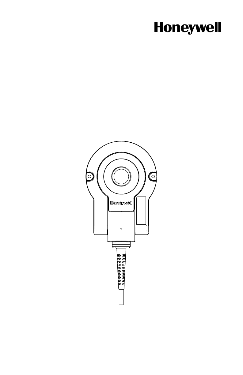
AP-010-BT and AP-100-BT
Access Point Device with Bluetooth®Wireless Technology
Installation Guide

Copyright
© 2008 Metrologic Instruments Inc. All rights reserved. No part of this work
may be reproduced, transmitted, or stored in any form or by any means
without prior written consent, except by reviewer, who may quote brief
passages in a review, or provided for in the Copyright Act of 1976.
Trademarks
Metrologic is a registered trademark of Metrologic Instruments, Inc.
Products identified in this document are hereby acknowledged as
trademarks, registered or otherwise, of Metrologic Instruments, Inc. or their
respective companies.

ii
TABLE OF CONTENTS
Introduction
Product Overview ............................................................................................. 1
Base Kit Components and Optional Accessories ............................................. 1
Components ..................................................................................................... 2
Mounting Specifications.................................................................................... 3
Cable Removal................................................................................................. 3
Product Labels ................................................................................................. 4
Installation
Cable to Access Point Connection ................................................................... 5
RS232 Host Connections ................................................................................. 5
USB Host Connections..................................................................................... 6
Keyboard Wedge Host Connections ................................................................ 6
RS485 Host Connections ................................................................................. 6
Establishing Communication
Between the Scanner and the Access Point Device......................................... 7
Access Point Device Operation
Page/Disconnect Button................................................................................... 8
Visual Indicators ............................................................................................... 8
Configuration Procedures
Metro Protocol Compatibility............................................................................. 9
CodeXML Protocol Compatibility.................................................................... 10
Access Point Device Configuration in CodeXML Mode.................................. 11
Optional Configuration Bar Codes.................................................................. 12

iii
TABLE OF CONTENTS
Uploading and Downloading Settings
Uploading Settings via MetroSet2.................................................................. 15
Downloading Settings via MetroSet2.............................................................. 16
Upgrading the Firmware..................................................................................... 17
Upgrading the Firmware in the Access Point Device...................................... 17
Upgrading FocusBT Firmware via the Access Point Device........................... 18
Design Specifications ......................................................................................... 19
Device and Cable Terminations
Device Pinout ................................................................................................. 20
Cable Pinout Connections .............................................................................. 21
Regulatory Compliance
EMC ............................................................................................................... 23
Limited Warranty ................................................................................................ 25
Index .................................................................................................................. 26
Contact Information and Office Locations........................................................... 27

1
INTRODUCTION
Honeywell’s access point devices with Bluetooth®wireless technology provide
customers with a flexible and convenient solution for wireless communication
in a variety of environments, including retail, healthcare, and manufacturing.
The access point device separates charging functions from communication
functions, allowing the user to optimize the available radio range.
Choose from Class II (10 meters) Bluetooth communication or Class I
(100 meters) to meet the specific needs of the application.
ACCESS POINT INTERFACE SUPPORT
Interfaces supported include:
AP-010-BT
OR
AP-100-BT
•RS232
•RS485S
•USB
•Keyboard Wedge
SApplicable for IBM®Host applications.
Base Kit Components and Optional Accessories
BASIC KIT
Part # Description
AP-010-BT
OR
AP-100-BT
Access Point Device (Class 2 radio: 10 m)
OR
Access Point Device (Class 1 radio: 100 m)
70-79035 Access Point Device with Bluetooth®Wireless Technology
Installation Guide*
* Available for download at www.metrologic.com
OPTIONAL ACCESSORIES
Part # Description
AC to DC Power Transformer- Regulated 5.2VDC @ 1A output.
46-00525 90VAC-255VAC United States, Canada, and Japan
46-00526 90VAC-255VAC Continental European
46-00527 90VAC-255VAC United Kingdom
46-00528 90VAC-255VAC Australia
46-00529 90VAC-255VAC China
www.metrologic.com2
INTRODUCTION
OPTIONAL ACCESSORIES
Part # Description
55-55500-3 RS232 Straight PowerLink Cable, Black
55-55502-N-3 Keyboard Wedge Straight Cable, Black
55-55512-3 RS485SApplications,Straight PowerLink Cable
55-55535-N-3 USB Type A Straight Cable, Black
55-55567-3 AUX Cable, Black
SApplicable for IBM®host applications.
Other items may be ordered for the specific protocol being used. To order additional items,
contact the dealer, distributor or call Metrologic’s Customer Service Department at
1-800-ID-METRO or 1-800-436-3876.
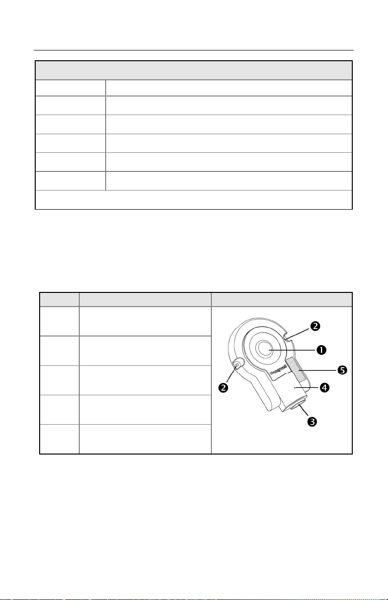
Components
ITEM NO. DESCRIPTION LOCATION
1 Page/Disconnect Button &
Blue LED (see page 8)
2 Mounting Holes, Qty. 2
3 10-Pin RJ45, Female Socket
4 Pinhole for Cable Release
(see page 5)
5 Address Bar Code Figure 1. Components
3
INTRODUCTION
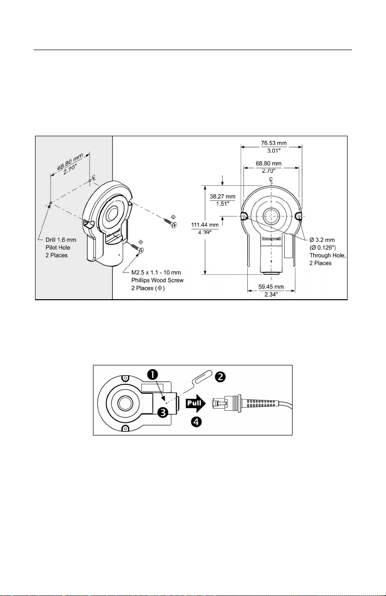
Mounting Specifications
1. Drill two, 1.6 mm pilot holes in the mounting surface. The pilot holes should
be located on a common centerline and be spaced 68.80 mm (2.70") apart.
2. Secure the access point device to the mounting surface with the
M2.5 x 1.1 - 10 mm, Phillips wood screws provided with the access point.
Figure 2. Mounting Specifications
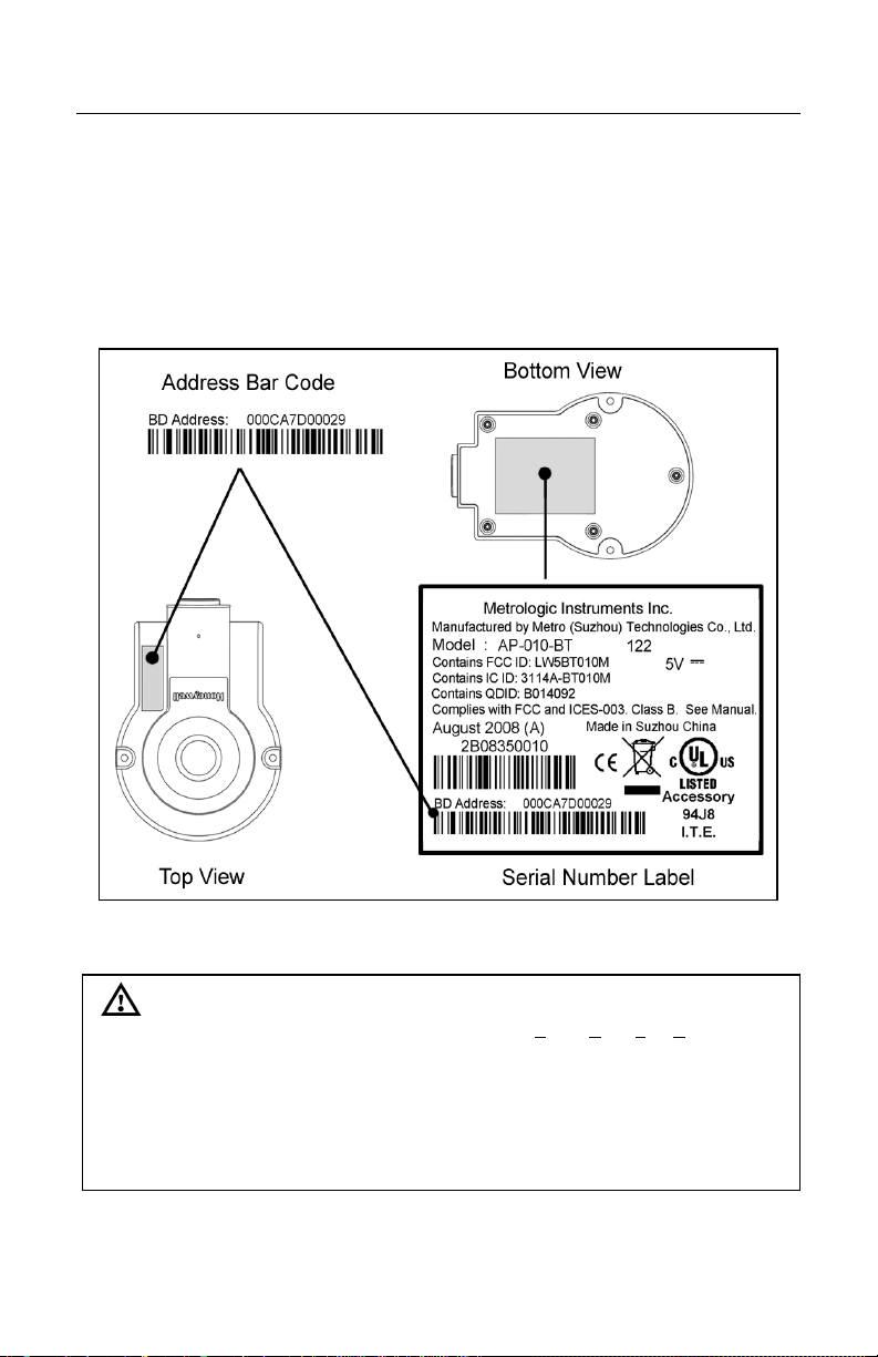
Cable Removal
Turn off power to the host system before removing the cable from the access
point device. If the cable is a PowerLink cable, disconnect the power supply on
the cable.
Figure 3. Cable Removal
1. Locate the small pinhole on the top of the access point device
(see figure above).
2. Bend an ordinary paperclip into the shape shown above.
3. Insert the paperclip into the pinhole on the device. Apply pressure to
release the connector’s lock.
4. Pull on the cable’s strain-relief to remove the cable.
www.metrologic.com4
INTRODUCTION
Product Labels
The serial number label located on the bottom of the access point device
provides important information including the model number, date of manufacture,
serial number, address bar code, safety and regulatory information. An
additional copy of the address bar code is location on the top of the device near
the Honeywell logo. The figure below provides examples of the labels and their
locations on the access point device.
Figure 4. Label Location with Examples
Caution
To maintain compliance with applicable standards, all circuits connected to the
scanner must meet the requirements for SELV (Safety Extra Low Voltage)
according to EN/IEC 60950-1.
To maintain compliance with standard CSA C22.2 No. 60950-1/UL 60950-1 and
norm EN/IEC 60950-1, the power source should meet applicable performance
requirements for a limited power source.
The AP-010-BT and AP-100-BT are intended for use with Listed UL computer
and/or Listed PS with LPS/Class 2 output.

5
INSTALLATION
Cable to Access Point Connection
1. Align the tab on the modular connector with the pinhole on the access point
device (see figure below).
2. Insert the modular connector into the device’s socket.
3. Test the cable’s connection to ensure the connector lock has engaged.
Important: If the cable is not fully latched, the unit can power intermittently.
4. Refer to pages 5 – 6 for the appropriate host connections applicable to the
interface type.
Figure 5. Cable Installation
RS232 Host Connections
1. Turn off power to the host system.
2. Connect the female, 9-Pin D-type
connector to a dedicated RS232
communication port on the host
system.
3. Plug the external power supply into
the power jack on the PowerLink
cable.
Check the AC input requirements of the power supply verify the
voltage matches the AC outlet. The outlet must be located near the
equipment.
See caution information on page 4.
4. Connect AC power to the transformer.
5. Turn on power to the host system.
Figure 6. RS232 Host Connections
www.metrologic.com6
INSTALLATION
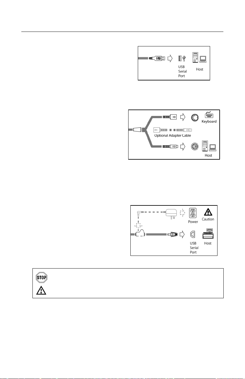
USB Host Connections
1. Turn off power to the host system.
2. Plug the USB connector into the to
a dedicated USB serial port.
3. Turn on power to the host system.
Keyboard Wedge Host Connections
1. Turn off power to the host system.
2. Disconnect the keyboard from the
host system.
3. Connect the “Y” ends of the
communication cable to the
keyboard and the keyboard port on
the host system. If necessary, use
the male/female adapter cable
supplied with the device for proper
connections.
4. Turn on power to the host system.
RS485SHost Connections
1. Turn off power to the host system.
2. Connect the SDL connector into
a dedicated Port 9 on the host
system.
3. Plug the external power supply
into the power jack on the
PowerLink cable
Check the AC input requirements of the power supply verify the voltage
matches the AC outlet. The outlet must be located near the equipment.
See caution information on page 4.
4. Connect AC power to the transformer.
5. Turn on power to the host system.
SApplicable for IBM®Host applications.
Figure 8. KBW Host Connections
Figure 7. USB Host Connections
Figure 9. RS485 Host Connections
Altri manuali per FocusBT AP-010-BT
2
Questo manuale è adatto per i seguenti modelli
1
Indice
Altri manuali Honeywell Punto di accesso wireless

Honeywell
Honeywell OW-FDAP31 Manuale utente

Honeywell
Honeywell FocusBT AP-010-BT Manuale utente

Honeywell
Honeywell WAP-PLUS Manuale utente

Honeywell
Honeywell 51306533 Manuale utente

Honeywell
Honeywell WAP-PLUS Manuale utente

Honeywell
Honeywell AVS Manuale utente

Honeywell
Honeywell WAP Manuale utente

Honeywell
Honeywell Field Device Access Point Manuale utente

Honeywell
Honeywell FocusBT AP-010-BT Manuale utente

Honeywell
Honeywell LYNX Series Manuale utente


