ATTACHMENT OF
BOOM SUPPORTS
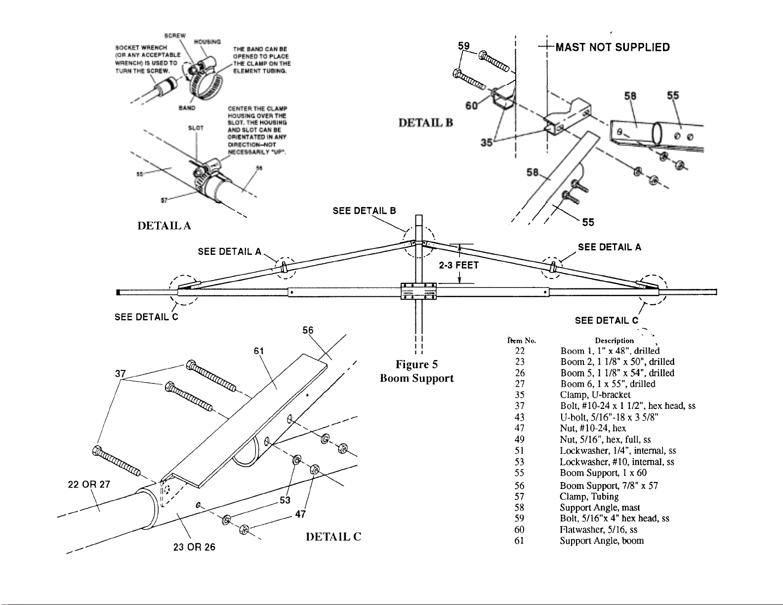
Select the boom support tubes (Items 55 and 56),
Support Angles (Items 58 and 61), U-brackets
(Item 35), Tubing clamps (Item 57), and as-
sociated hardware as shown in Fi
ure 5.
INSTALLATION
the balun assembly. Tighten securely and tape
coax to the boom every 2 feet for strain relief. Do
Not allow. the feedline to touch any director ele-
ment.
.The boom supports may be assembled either
above or below the boom. Either position will give
adequate support to the antenna. Figure 5 shows
the supports above the boom. Assemble the anten-
na and boom support to a temporary mast first to
determine the desired dimensions of the boom
support.
Attach the antenna to your mast with the balun
assembly/coax on the bottom of the boom. Posi-
tion the boom support for minimum boom sag,
and ti
hten securel
.
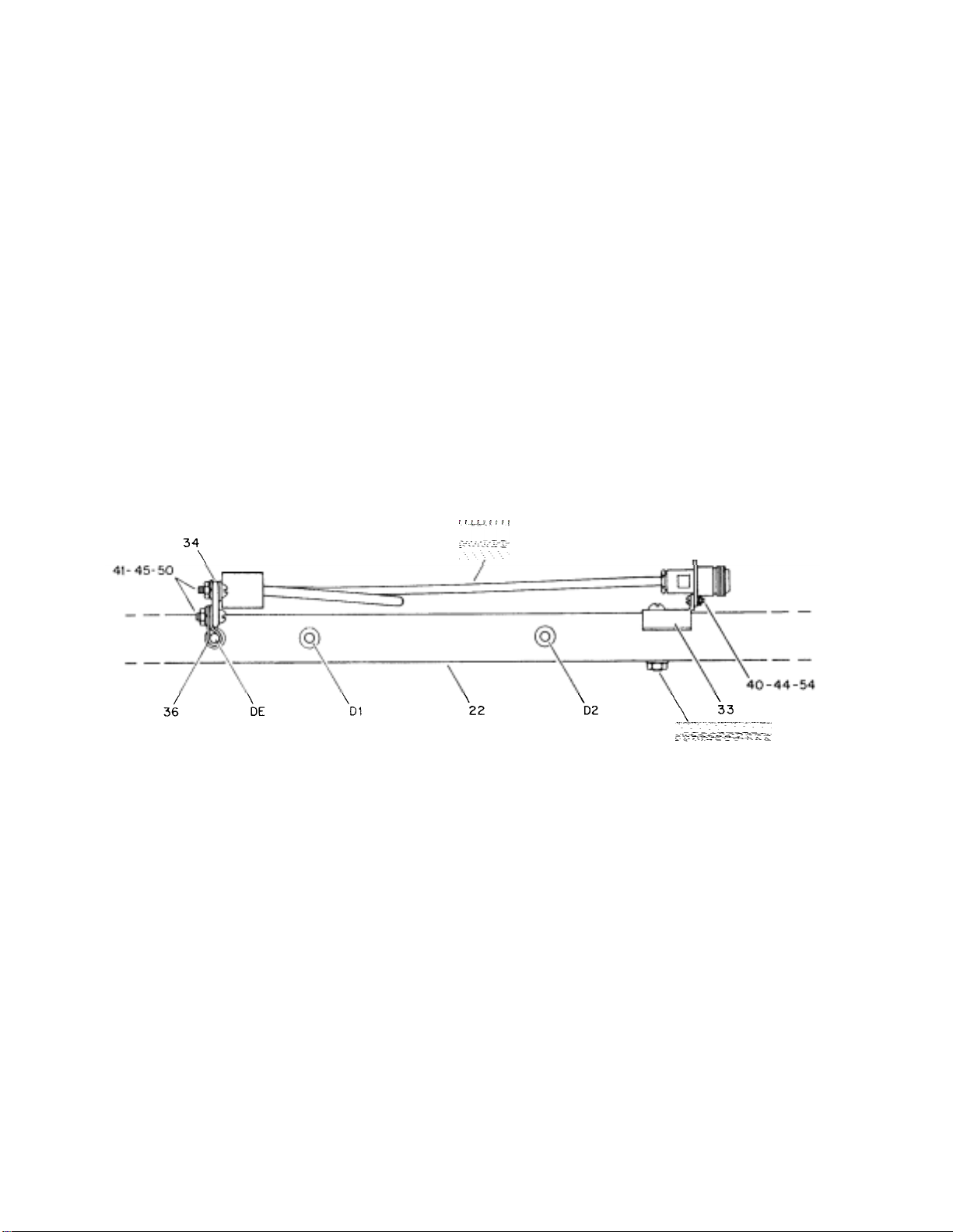
Recommended feedline for the 70-31 DX antenna
is a low-loss cable such as Belden 8214 or 9913
with t
e "N" connectors.
Attach a Mast Support Angle (Item 58) to the end
of each 1" x 60" support tube (Item 55) using
#10-24 x 1 1/2" hardware. Attach a Boom
Support Angle (Item 61) to the end of each 7/8" x
57" support tube (Item 56) using the same
hardware.
Loosely assemble the support tubes together as
shown in Detail A of Figure 5, using a No. 10
tubing clamp (Item 57). Arrange the Support
Angles as shown in Figure 5. The 7/8" support
tube should be centered over the 1 1/8" boom
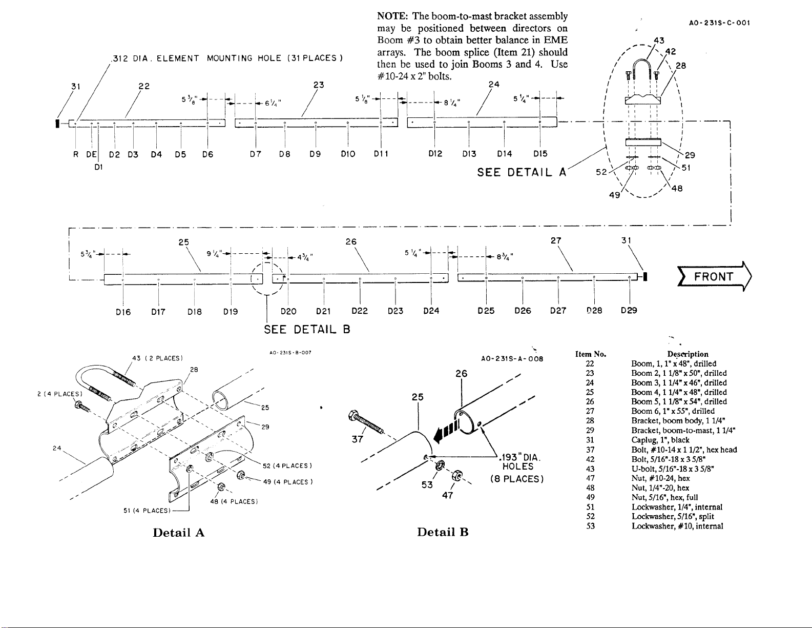
tube. The boom-to-mast bracket should be as-
sembled on the boom for best balance, using the
coaxial cable to be installed with the antenna. See
Note in Fi
ure 1.
WARNING
DO NOT ALLOW ANY PART OF THE
ANTENNA TO TOUCH POWERLINES.
THIS COULD CAUSE SEVERE BURNS
OR FATAL INJURIES.
When mounting the 70-31 DX beam above or
below any other antennas, allow at least 5 feet for
minimum interaction.
When stacking more than one antenna, keep the
balun assemblies all on the same side of the
booms. This will ensure proper phasing.
Assemble the U-brackets to the temporary mast
above or below the boom-to-mast brackets.
Attach the tubing assemblies to the boom and to
the Ubracket assembly. Tighten the 5/16" bolts in
the U-bracket assembly to your preferred distace
from the boom. Securely tighten the tubing
clamps, when you are sure the boom is level.
Securely tighten the support asembly to the boom
at
a
h
n
The maximum stacking distance should be about
2.7 wavelengths or 74 inches (1.88 m) in the E-
plane and 2.6 wavelengths or 71 inches (1.80 m)
in the H-
lane.
Remove the U-brackets and the boom-to-mast
brackets from the temporary mast.