Hysolis Split Phase SPS6K Manuale utente

User Manual
Solar Power Station
SPS6K Split Phase Series

Dear Customer,
Thank you very much for purchasing the Hysolis SPS-6KW Series! We designed this
product to help grant you energy independence. We have the utmost confidence in this
product’s performance and quality. Please feel free to contact us at Hysolis.com if you have
any questions. Enjoy using your Hysolis Solar Power Station, and may it positively affect your
future endeavors!
Sincerely,
The Hysolis Team
Catalogue
1 Product features ---------------------------------------------------------------------01
2 Installation and storage instruction----------------------------------------------01
3 Equipment diagram, operation instructions-----------------------------------02
4 System Wiring Instructions--------------------------------------------------------10
5 Power ON / OFF --------------------------------------------------------------------13
6 Maintenance -------------------------------------------------------------------------15
7 Common faults and troubleshooting guide ----------------------------------16
8 Technical specification sheet ----------------------------------------------------17
9 System Wiring Diagram------------------------------------------------------------18
10 WiFi configuration & APP setup -------------------------------------------------19
Note: Hysolis reserve the right of modification on this user manual without any notice.

1
1 Product features
● Double CPU intelligent control technology, excellent performance;
● Dual isolated transformer, higher safety standard.
● 3 working modes for optional. (Utility first, Battery first, Energy saving);
● Smart cooling fan control, safe and reliable;
● Pure sine wave output, protect your loads from dirty power;
● Wide input voltage range,high-precision output with automatic voltage regulator (AVR);
● The LCD display showing the unit working status real time;
● The output overload, short circuit protection, automatic protection and alarm;
● The intelligent solar maximum power point tracking charge controller with overcharge,
overdischarge protection, current limiting charging, multiple protection;
2 Installation & storage
2.1 Off packet inspection
2.1.1 Open the package, check the product overall, accessories, user manual.
2.1.2 If the unit is damaged during the shipment transit, please inform the carrier and dealer
before you start to use it.
2.2 Installation & storage
2.2.1 Installation should be done by qualified technicians, or assisted by local distributors.
2.2.2 Protection materials are needed for transporting the unit. Move the unit from low
temperature to high temperature environment, it may get wet on surface. Please make sure
the unit is completely dry before using.
2.2.3 The working environment is supposed to be dry, clean and ventilated. Do not cover or
block the vents. In maintain good heat dissipation, 20cm air circulation space is required for
peripheral equipment;
2.2.4 To conserve battery, turn off the Battery Breaker before periods of inactivity (>2 days),
unless solar power is connected.

2
3 Diagram & operation instructions
3.1 Front panel

3
3.2 Side panel
Guide
1- AC input breaker
2- AC input wiring terminals
3- AC output wiring terminals
4- AC output breaker
5- Solar input wiring terminals
6- AC output sockets
7- Solar input breaker
8- Battery breaker
9- WIFI Indicator
10 - Expansion Battery Port

4
3.3 Display Instructions
3.3.1 LCD display and function key allows user to check the SPS working status and set
working modes. Such as: AC Input / AC output voltage, AC frequency, working mode, the
battery level, PV input power, PV current, PV voltage, loads percentage of the unit capacity,
error codes and etc;
3.3.2 Keys Instructions
Function keys
Description
Power
ON/OFF
Inverter Power ON/OFF
Page UP
Click to view the last page. Or set the increment
under the setting manual.
Page
DOWN
Click to view the next page. Or set the
decrement under the setting manual.
Function
keys
Long press to enter setting mode. Or short
press to confirm the settings and return to the
main page.

5
3.3.3 LED indicator instructions
LED indicators
Instructions
PV
Green
ON
PV is charging
OFF
PV is not charging
LINE
Green
ON
The AC input power is connected and bypassing.
OFF
The AC input is disconnected.
INV
yellow
ON
The inverter is ON, Powered by the battery.
OFF
The inverter is OFF.
FAU
red
ON
AC output overload or Inverter fault.
OFF
The Inverter is working normally.
3.3.4 LCD display instruction
3.3.4.1 On the main page, press DOWN or UP to scroll pages .

6
3.3.4.2 Settings.
Under the main page, long press Funct key for 5 seconds or to enter the setting menu, and
then press DOWN or UP to view the sub-menu. The function of P0/P1/P2/P3/P4 in the
flashing state is as follows:
Main Menu
Functions
P4
Buzzer mode
P3
Inverter AC-DC charging current
P2
Inverter AC-DC charging voltage
P1
Inverter working mode
P0
Save & Exit
3.3.5 Parameters Setting
3.3.5.1 Buzzer mode Settings
Under the main page, long press the Funct button for 5 seconds to enter the setting menu,
press the DOWN button to select the buzzer information P4, press the Funct button to enter
the P4 setting page, turn ON/OFF the buzzer state through DOWN or UP key, and press the
Funct key to save and exit.
ON Indicates that the buzzer is ON;
OFF Indicates that the buzzer is OFF;

7
3.3.5.2 Inverter AC charging current setting
Under the main page, long press the Funct button for 5 seconds to enter the setting menu.
Press the DOWN button to select the inverter charging current information P3. Press the
Funct button to enter the P3 setting page. Through DOWN or UP keys, increase /decrease
The charge current of the inverter (100%-80%-60%-40%-20%). Pressed Funct to save and
exit.
8
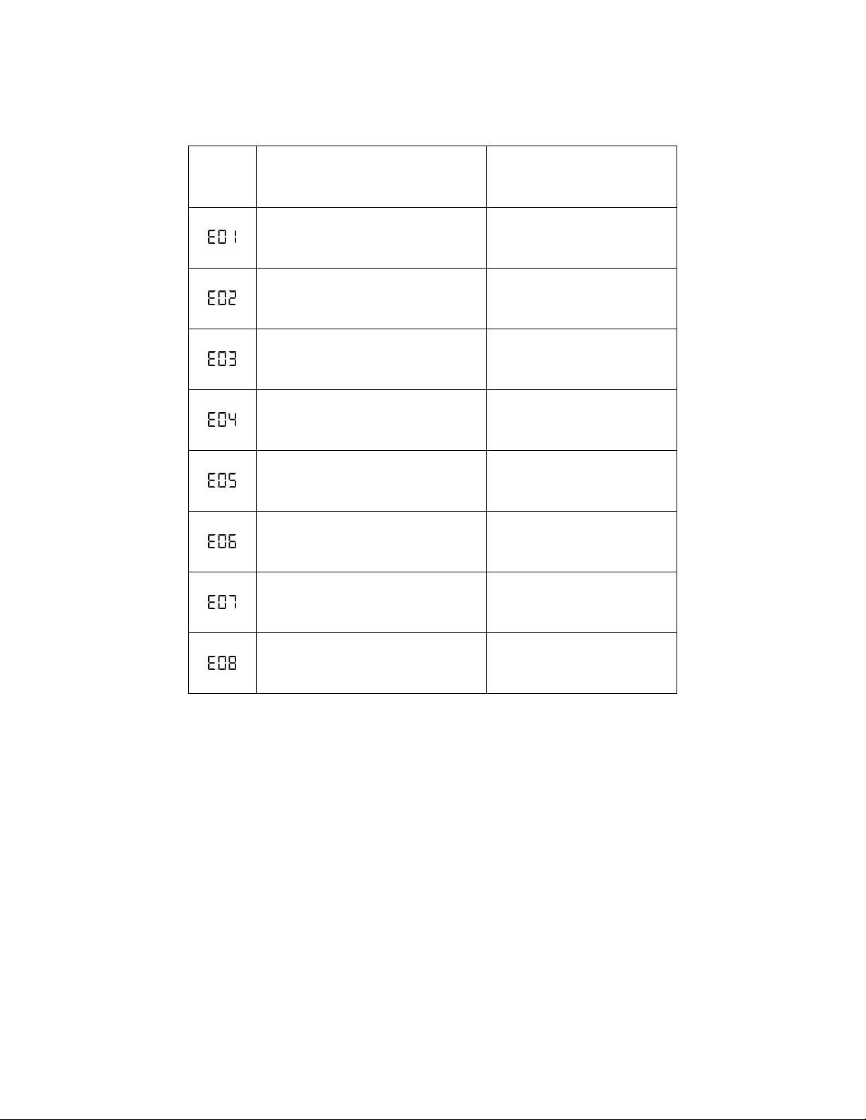
3.3.5.3 Error code and solution
Error
code
Fault description
Solution
Overcurrent of MOSFETS board
Contact tech support if still
having this issue after
restarting
Output short circuit
Loads shortcircuit or extreme
overloaded.
Overloaded
Remove some loads or reduce
the loads power.
Over-temperature
Check whether cooling fan is
working well or vent might be
covered
Battery overvoltage
Check the battery voltage &
connection
Battery undervoltage
Recharge the battery or
replace battery
Reverse connection between
transformer and heat-sink on power
board
Exchange and reconnect.
Protection when low voltage output
Contact tech support if it’s
reoccurs after restart.
Indice
Altri manuali Hysolis Generatore portatile


