Ideal Heating Halo Manuale utente

i
d
e
a
l
h
e
a
t
i
n
g
.
c
o
m
H
a
l
o
H
e
a
t
&
S
y
s
t
e
m
I
n
s
t
a
l
l
a
t
i
o
n
G
u
i
d
e


HALO HEAT & SYSTEM RF
UIN: 222141
Wireless single zone Heat & System Programmable Room Thermostat (PRT)
Compatible with the following boilers: Logic Heat
H, Logic Heat H IE, Logic System S, Logic System S
IE, Logic+ Heat H, Logic+ System S, Logic Max Heat
H, Logic Max Heat H IE, Logic Max System S, Logic
Max System S IE Keston System, Vogue System,
Vogue GEN2 System, Vogue Max System, Vogue
Max System IE.
To install Halo with older boilers further details can
be found at idealheating.com
The Ideal Halo Heat & System RF is a wireless
PRT that is paired with the Halo Smart Interface
installed alongside the boiler. The Smart Interface
is fitted into the Smart Interface Bracket and is
wired directly to the boiler and communicates to
the boiler via OpenTherm. A Smart Wiring Centre
is provided to control central heating components
(zone valves, cylinder thermostat, circulating
pump). The Halo unit is powered by 4 AA batteries.
Communication from the Smart Interface to
the PRT is through Zigbee, a local RF protocol.
Communication between the Smart Interface and
Smart Wiring Centre is also via Zigbee removing
the need to wire the Smart Wiring Centre directly
to the boiler.
The Halo Heat & System, including the Smart
Wiring Centre and Smart Interface bracket, must
be installed by a competent person with the
appropriate safety qualifications. Please read
the instructions carefully. Failure to follow these
instructions can damage the product or cause a
hazardous condition.
These instructions are applicable to the Ideal
boiler models stated and must not be used with
any other make or model of boiler. This product
must be installed to all applicable standards.
Always isolate the mains supply before
installing or working on any components that
require a 230V ac supply.
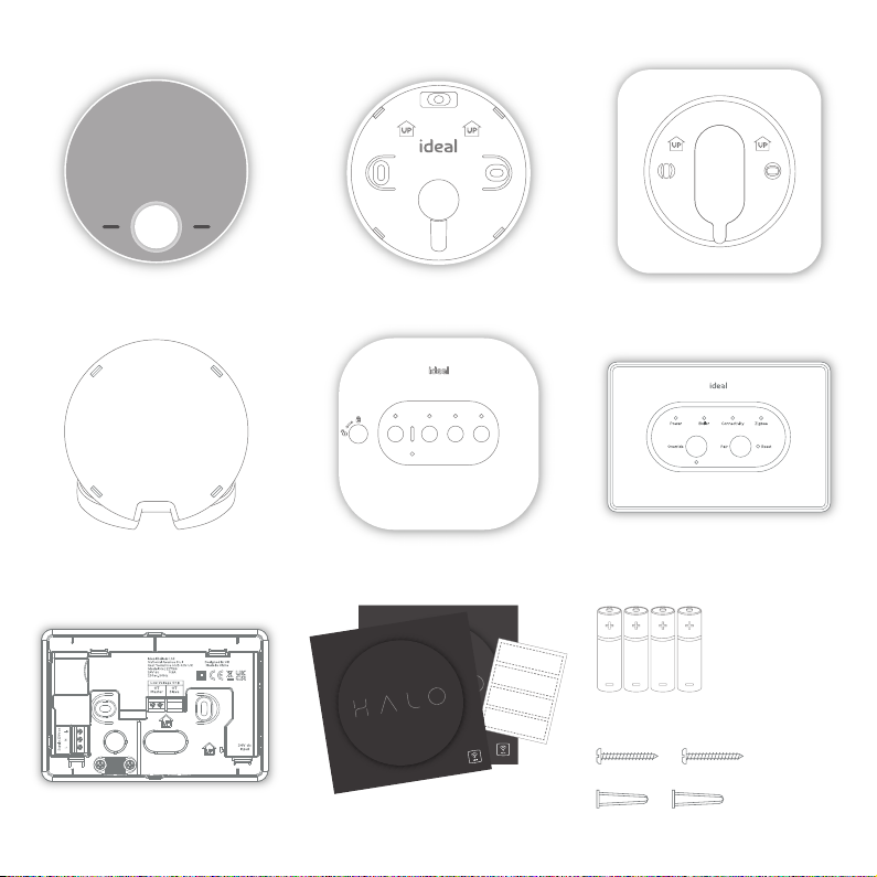
A. KIT CONTENTS
1. Halo Combi PRT display unit
4. Desk stand
2. PRT rear housing
5. Smart Wiring Centre 6. Smart Interface
5. Smart wiring centre
10. Screws & RawlplugsTM
9. 4 AA Batteries
3. Trim plate
id
e
a
lh
e
a
ti
n
g.
c
o
m
H
a
lo
H
e
a
t
&
S
y
st
e
m
In
s
ta
ll
at
io
n
G
ui
d
e
Zone 1
Zone 1
Zone 2
Zone 2
7. Smart Interface bracket
8. Install/user guides, wiring diagrams
and zone valve labels
id
e
a
lh
e
a
ti
n
g.
c
o
m
H
a
lo
H
e
a
t
&
S
y
st
e
m
In
s
ta
ll
at
io
n
G
ui
d
e

B. LOCATION
GUIDELINES
The Halo Heat & System uses
wireless Zigbee communication
from the Smart Interface to the
Smart Wiring Centre and Halo
PRT up to a maximum distance
of 30 meters. Occasionally house
constructions and materials
can reduce this communication
range and it is advisable, where
possible, to try and avoid
directing communications
through metal frames or solid
concrete walls.
If the distance between the
Halo PRT and Smart Interface
or the Smart Wiring Centre
and Smart Interface is greater
than 30 meters or the install
location is challenging, consider
using the Zigbee Booster (UIN
221132, further details available at
idealheating.com)
1.2-1.5m
1. Mounted 1.2-1.5m above the floor 2. Not above a radiator/heat source
3. Not in direct sunlight 4. Away from any drafts
5. Not fitted behind curtains 6. Internal use only

C. SYSTEM OVERVIEW
This is a simplified diagram of how the Halo units, Smart Wiring Centre and Smart
Interface communicate. Some wiring and pipework has been omitted for clarity.
HALO PRT
SI Smart Interface
Pipework
RF Connection
Wiring
TOP TIP: For a robust signal between units, where possible, ensure that the
line of communication between the Smart Interface and other units is not
through any stone or metallic object.
Cylinder
with
cylinder
stat
Smart
Interface in
bracket
30m*
30m*
*solid and metallic objects will reduce maximum distance
System components
Pump
3-port
or 2-port
valve
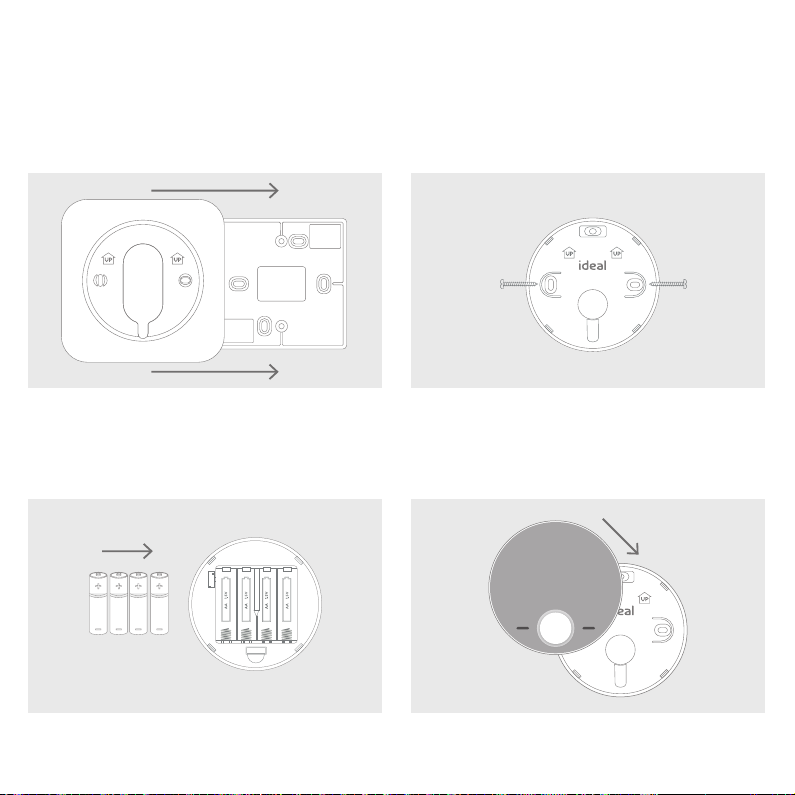
1. The Halo can be installed with or without the provided
trim plate.
3. Insert the 4 AA batteries provided into the front housing
of the Halo. Pay close attention that the orientation of the
batteries is as indicated in the housing.
4. Locate the front housing (display) in position
perpendicular to the rear housing and clip into place.
2.
If no trim plate is required, use the rear housing of the
Halo to position the unit on the wall, alternatively secure
rear housing to trim plate. Take care not to overtighten
the screws.
D. INSTALLING THE HALO PRT
The Halo can be either wall mounted or desk mounted.
WALL MOUNTING THE HALO
If there are any concerns regarding signal strength and location of the wall mounted PRT it is advisable to
pair the control and check the signal strength before fixing to the wall.

1. The Halo has an integrated rear housing and desk stand.
3. Clip the combined rear housing and desk stand
into place.
2.
Insert the 4 AA batteries provided into the front housing
of the Halo. Pay close attention that the orientation of
the batteries is as indicated in the housing.
DESK MOUNTING THE HALO

E. INSTALLING THE SMART WIRING CENTRE
The Smart Wiring Centre controls the operation of the zone valves for the central heating system. The Smart
Wiring Centre communicates wirelessly to the Smart Interface via the Zigbee RF protocol. The Smart Wiring
Centre must be mounted to a fixed surface before installation.
Removing the cover
Using a suitable screwdriver turn the locking key
one quarter turn anticlockwise to the [UNLOCK]
position. Remove the front panel by lifting the left
hand edge first. Assemble in reverse order. Always
remember to lock the front panel to the Smart
Wiring Centre.
Wall mounting the Smart Wiring Centre
Please refer to the location guidelines before fixing
the Smart Wiring Centre to the wall.
Using the 4 fixing locations on the Smart Wiring
Centre secure to the Wall with adequate fixings
for the wall type.
Do not remove the cover unless you are qualified to do so.
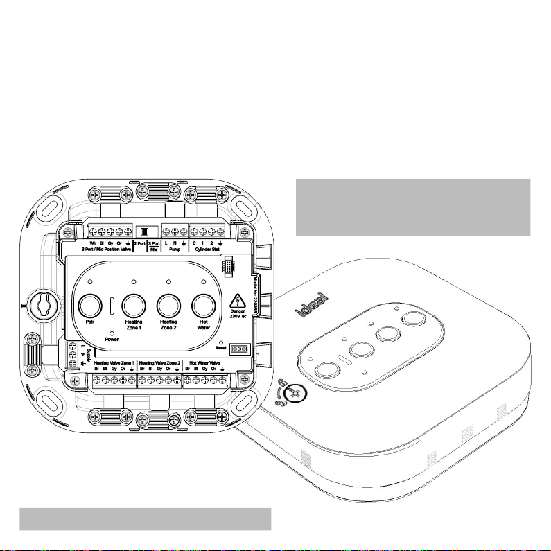
F. WIRING THE SMART INTERFACE
The Smart Wiring Centre must be installed by a competent person with the appropriate safety qualifications.
All wiring must be adequately sheathed and insulated.
Isolate any 230V ac mains supply to the Smart Wiring Centre and any other linked components before
commencing works.
For detailed wiring instructions please refer to the wiring diagram fold-out in the kit. This gives detailed
wiring on S-plan and Y-plan systems. Ensure selector switch is in the correct position for the installed
system. Wiring can either be installed from the rear of the device through the back housing cut outs or
surface mounted. When surface mounting any wiring, use the reversible omega clamps provided. Remove
all appropriate cut outs on front cover for wiring.
TOP TIP: This kit comes with labels to identify
heating zones. Fix one to the zone valve and
the other to the inside cover of the smart
wiring centre to easily identify each zone.
Do not reinstate power once wiring is complete.
Altri manuali per Halo
2
Indice
Altri manuali Ideal Heating Stufa


Manuali Stufa popolari di altre marche


Empire Heating Systems
Empire Heating Systems WCC65 Manuale utente

Wetekom
Wetekom 92 86 43 Manuale utente

Desa
Desa SPC170-F Manuale utente

Watlow
Watlow Watrod Electric Tubular Heaters Manuale utente

Haverland
Haverland ECO-DRY GPS Series Manuale elenco delle parti

Stelpro
Stelpro ASILVC2060 Series Manuale utente