IFM LK122 Series Manuale utente

Operating instructions
Electronic level sensor
LK122x
80260475/ 00 01 / 2017
UK

2
Contents
1 Preliminary note���������������������������������������������������������������������������������������������������4
1�1 Symbols used ������������������������������������������������������������������������������������������������4
2 Safety instructions �����������������������������������������������������������������������������������������������4
3 Items supplied������������������������������������������������������������������������������������������������������5
4 Functions and features ����������������������������������������������������������������������������������������5
4�1 Applications ���������������������������������������������������������������������������������������������������5
4�2 Restriction of the application area ����������������������������������������������������������������6
5 Getting started �����������������������������������������������������������������������������������������������������6
5�1 Example configuration �����������������������������������������������������������������������������������7
6 Function���������������������������������������������������������������������������������������������������������������8
6�1 Measuring principle ���������������������������������������������������������������������������������������8
6�2 Operating principle / features of the unit��������������������������������������������������������9
6�2�1 Notes on the integrated overflow prevention ����������������������������������������9
6�2�2 Display and switching functions����������������������������������������������������������10
6�2�3 Offset for indicating the real level in the tank�������������������������������������� 11
6�2�4 Defined state in case of a fault ����������������������������������������������������������� 11
6�2�5 IO-Link function ���������������������������������������������������������������������������������� 11
6�3 Password protection against inadvertent manipulation �������������������������������12
7 Installation����������������������������������������������������������������������������������������������������������12
7�1 Other installation notes��������������������������������������������������������������������������������14
7�1�1 Marking of the installation height �������������������������������������������������������14
8 Electrical connection������������������������������������������������������������������������������������������15
9 Operating and display elements ������������������������������������������������������������������������16
10 Menu����������������������������������������������������������������������������������������������������������������17
10�1 Menu structure�������������������������������������������������������������������������������������������17
10�2 Password protection ����������������������������������������������������������������������������������18
11 Parameter setting���������������������������������������������������������������������������������������������18
11�1 Parameter setting in general����������������������������������������������������������������������18
11�2 Basic settings ��������������������������������������������������������������������������������������������19
11�2�1 Set unit of measurement [uni]�����������������������������������������������������������19
11�2�2 Set offset [OFS] ��������������������������������������������������������������������������������19

3
UK
11�2�3 Set medium [MEdI] ���������������������������������������������������������������������������20
11�2�4 Set overflow prevention [OP] ������������������������������������������������������������20
11�2�5 Adjust the overflow prevention [cOP]������������������������������������������������21
11�3 Setting the output signals for OUT1�����������������������������������������������������������22
11�3�1 Setting the output function [ou1] ������������������������������������������������������22
11�3�2 Define switching limits [SP1] / [rp1] (hysteresis function) �����������������22
11�3�3 Define switching limits [FH1] / [FL1] (window function) ��������������������22
11�3�4 Set switch-on delay [dS1] �����������������������������������������������������������������22
11�3�5 Set switch-off delay [dr1]�������������������������������������������������������������������23
11�3�6 Define switching logic [P-n]���������������������������������������������������������������23
11�3�7 Set response of the output in case of a fault [FOU1]������������������������23
11�3�8 Configure display [diS]����������������������������������������������������������������������23
11�3�9 Reset all parameters to factory setting [rES] ������������������������������������23
11�4 Changing the password [CodE] �����������������������������������������������������������������24
11�5 Enter password [KEy�C] �����������������������������������������������������������������������������24
12 Operation���������������������������������������������������������������������������������������������������������24
12�1 Operation indication�����������������������������������������������������������������������������������25
12�2 Read the set parameters ���������������������������������������������������������������������������25
12�3 Error indications�����������������������������������������������������������������������������������������26
12�4 Output response in different operating states��������������������������������������������27
13 Technical data��������������������������������������������������������������������������������������������������27
13�1 Setting values [OFS]����������������������������������������������������������������������������������27
13�2 Setting values [OP]������������������������������������������������������������������������������������28
13�3 Calculation aids [OP] ���������������������������������������������������������������������������������29
13�3�1 Definition "from the cover“ ����������������������������������������������������������������29
13�3�2 Definition "from the bottom"��������������������������������������������������������������30
13�4 Setting ranges [SP1] / [FH1] and [rP1] / [FL1] �������������������������������������������30
14 Maintenance/cleaning/change of medium �������������������������������������������������������31
15 Factory setting �������������������������������������������������������������������������������������������������31

4
1 Preliminary note
Technical data, approvals, accessories and further information at www�ifm�com�
1.1 Symbols used
►Instructions
> Reaction or result
[…] Designation of keys, buttons or indications
→Cross-reference
Important note
Non-compliance may result in malfunction or interference�
Information
Supplementary note
2 Safety instructions
• Read this document before setting up the product and keep it during the entire
service life�
• The product must be suitable for the corresponding applications and environ-
mental conditions without any restrictions�
• Only use the product for its intended purpose (→ Functions and features).
• Only use the product for permissible media (→ Technical data).
• If the operating instructions or the technical data are not adhered to, personal
injury and/or damage to property can occur�
• The manufacturer assumes no liability or warranty for any consequences
caused by tampering with the product or incorrect use by the operator�
• Installation, electrical connection, set-up, operation and maintenance of the
product must be carried out by qualified personnel authorised by the machine
operator�
• The unit and the accessories (e�g� cable) must be effectively protected against
damage�

5
UK
3 Items supplied
• 1 LK122x sensor
• 1 operating instructions
• 1 stainless steel tube clip (for fixing the installation height)
In addition, the following may be necessary for installation and operation:
• 1 climatic tube (for operation of the unit with aqueous media of temperatures
> 35 °C)� The climatic tube restricts the application area of the unit (→ 4.2)�
►In the event of incomplete or damaged items supplied please contact ifm
electronic�
►Only use accessories from ifm electronic�
Accessories: www�ifm�com
The optimum function is not ensured when using components from other
manufacturers�
4 Functions and features
4.1 Applications
The unit was especially designed to meet the requirements of machine tool
building� It is particularly suitable for monitoring coolant emulsions (also dirty) as
well as cutting and hydraulic oils�
The unit has a building authority approval according to the German
Federal Water Act (WHG)�
When used as overflow prevention according to the German Federal Wa-
ter Act (WHG), observe the Technical description� → www�ifm�com

6
4.2 Restriction of the application area
• The unit is not suitable for:
- acids and alkalis,
- hygienic and electroplating applications,
- highly conductive and adhesive media (e�g� glue, shampoo),
- granulates and bulk material,
- use in grinders (increased risk of formation of deposits)�
• It is possible that foam of good conductivity is detected as level:
►Check proper function by an application test�
• For water-based media with temperatures > 35 °C install the unit in a climatic
tube (accessories)�
►Check proper function by an application test�
When used as overflow prevention according to the German Federal
Water Act (WHG), no climatic tube must be used�
5 Getting started
For fast set-up, the example configuration described in the following can be used
for most applications� The indicated minimum distances apply exclusively to the
described case�
7
UK
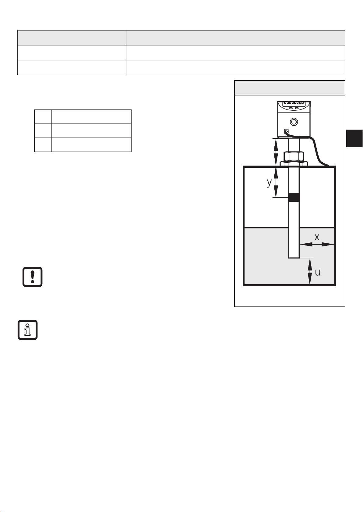
5.1 Example configuration
Unit: LK1222 (probe length L= 264 mm)
Medium to be detected: Mineral oil
Installation environment: Metal tank, installation to fig� 5-1
►Install unit�
►Observe the distances (x), (u) and (c):
x: min� 4�0 cm
u: min� 1�0 cm
c: max� 14�0 cm
►Ground sensor and tank via an electrical connec-
tion (→ 8)�
►Observe the parameter setting sequence:
- [MEdI] = [OIL�2] → 11.2.3
- [OFS] = (u); e�g� (u) = 2�0 cm (→ 6.2.3)
- [OP]: Set the overflow prevention OP at a dis-
tance (y) greater than 4�5 cm below the
mounting element�
For distances (y) smaller than 4�5 cm there
may be malfunctioning and error messages
during the adjustment process [cOP]�
Fig. 5-1
OP
c
Step increment and setting range: → 13.2
Calculation aids for [OP]: → 13.3
►Adjust overflow prevention OP to [cOP] → 11.2.5
>The unit is ready for operation.
►Make further settings if necessary�
►Check whether the unit operates correctly�

8
6 Function
6.1 Measuring principle
The sensor determines the level according to the capacitive measuring principle:
• An electrical field [E] is generated
and influenced by the medium to be
detected� This change to the field
causes a measurement signal that is
electronically evaluated�
• The dielectric constant of a medium
is important for its detection� Media
with a high dielectric constant
(e�g� water) generate a strong
measurement signal, media with a
low dielectric constant (e�g� oils) a
correspondingly lower signal�
• The active measurement zone of
the sensor probe is composed of
16 capacitive measuring segments�
They generate measurement
signals depending on the degree of
coverage�
Fig. 6-1
A II
E
I: Inactive zone
A: Active zone (16 active segments)
E: Electrical field
Dimensions → Technical data sheet

9
UK
6.2 Operating principle / features of the unit
The unit can be flexibly installed in tanks of different sizes�
2 outputs are available:
OUT1 Switching signal for level limit value/IO-Link
OUT-OP Switching signal for level limit value (overflow prevention)
OUT1 can be freely configured, OUT-OP is fixed to NC and has a fixed hysteresis
(a few mm)�
6.2.1 Notes on the integrated overflow prevention
With the parameter [OP] (OP = overflow prevention), one of the upper measuring
segments is defined as integrated overflow prevention OP�
• The overflow prevention OP is the maximum limit of the measuring range�
The switch point [SP1] / [FH1] is always below [OP]�
• The overflow prevention OP is assigned to the output OUT-OP!
• Typically the overflow prevention OP reacts when the selected measuring
segment has been reached (a few mm before the set OP value)�
• The overflow prevention OP reacts immediately and without delay�
• The response of the overflow prevention OP is indicated on the display
("Full" and indication of the current level change every second)�
10
6.2.2 Display and switching functions
The unit displays the current level, selectable in cm or inches� The display unit
is defined by parameter setting� The set unit of measurement and the switching
status of the outputs are indicated by LEDs�
The unit signals via two switching outputs (OUT1, OUT-OP) that a set limit has
been exceeded or that the level is below the limit� The output configuration for the
switching output OUT-OP cannot be configured (see above)� The following output
functions are available for the switching output OUT1:
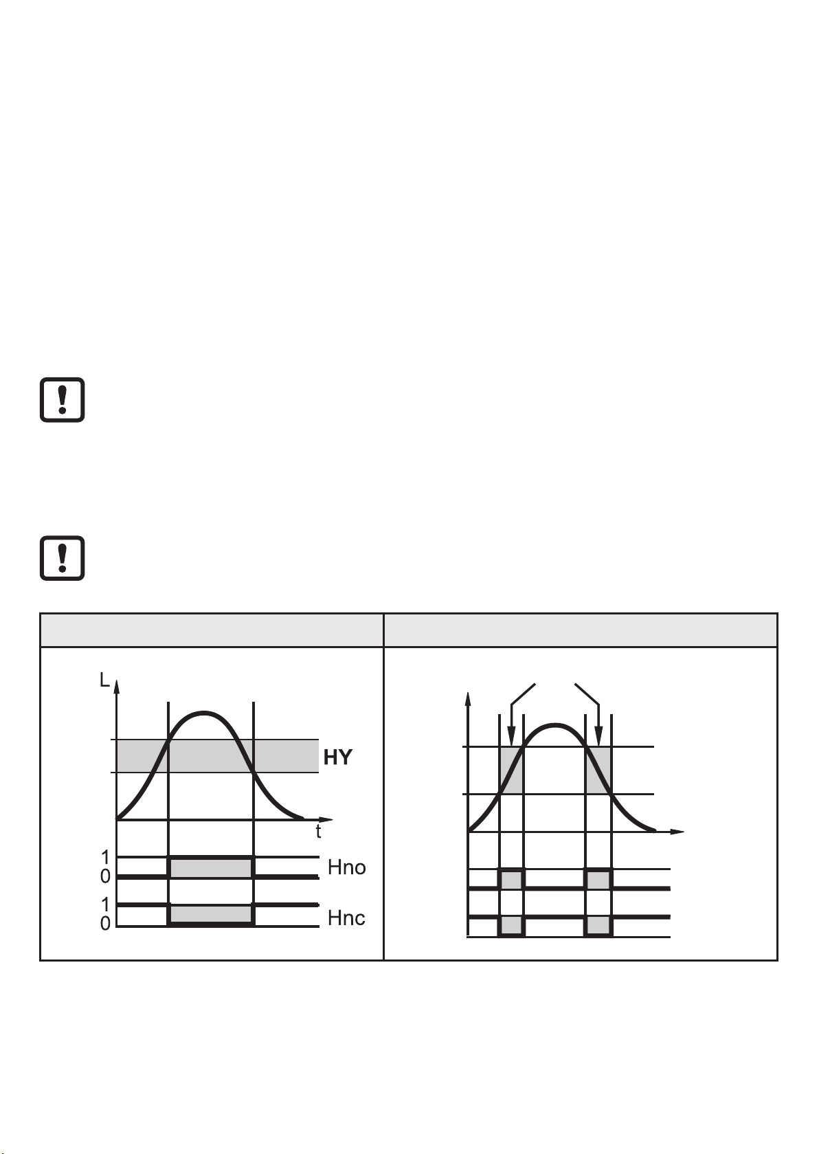
• Hysteresis function / normally open (fig� 6-2): [ou1] = [Hno]
• Hysteresis function / normally closed (fig� 6-2): [ou1] = [Hnc]
First the switch point [SP1] is set, then the switch-off point [rP1] with the
requested difference�
• Window function / normally open (fig� 6-3): [ou1] = [Fno]
• Window function / normally closed (fig� 6-3): [ou1] = [Fnc]
The width of the window can be set by means of the difference between
[FH1] and [FL1]� [FH1] = upper value, FL1 = lower value
Fig. 6-2 Fig. 6-3
SP
rP
t
L
FH
FL
1
0
1
0
FE
Fno
Fnc
L: Level HY: Hysteresis FE: Window
For the output OUT1 a switch-on and switch-off delay of max� 60 s can be set (e�g�
for especially long pump cycles)�
→ 11.3.4 and → 11.3.5
Questo manuale è adatto per i seguenti modelli
3
Indice


