Index Everest-D Manuale utente

Version2.0
Page1
INDEXEVERESTSERVICEMANUAL
IndexBraillePrinterCompany
Table of contents
1. Mechanics 2
1.1 Disassembling 2
1.1.1 Backplate 2
1.1.2 Expose the main board 3
1.1.3 Open the front panel cover 3
1.1.4 Right casing 4
1.1.5 Left casing 4
1.1.6 Remove the main board 5
1.1.7 Loosen the front panel cover 5
1.1.8 Fan 6
1.1.9 Front panel cover indicator 6
1.1.10 Transformer 7
1.1.11 Roll bearing, left side. 7
1.1.12 Stepper motor, paper feeding 8
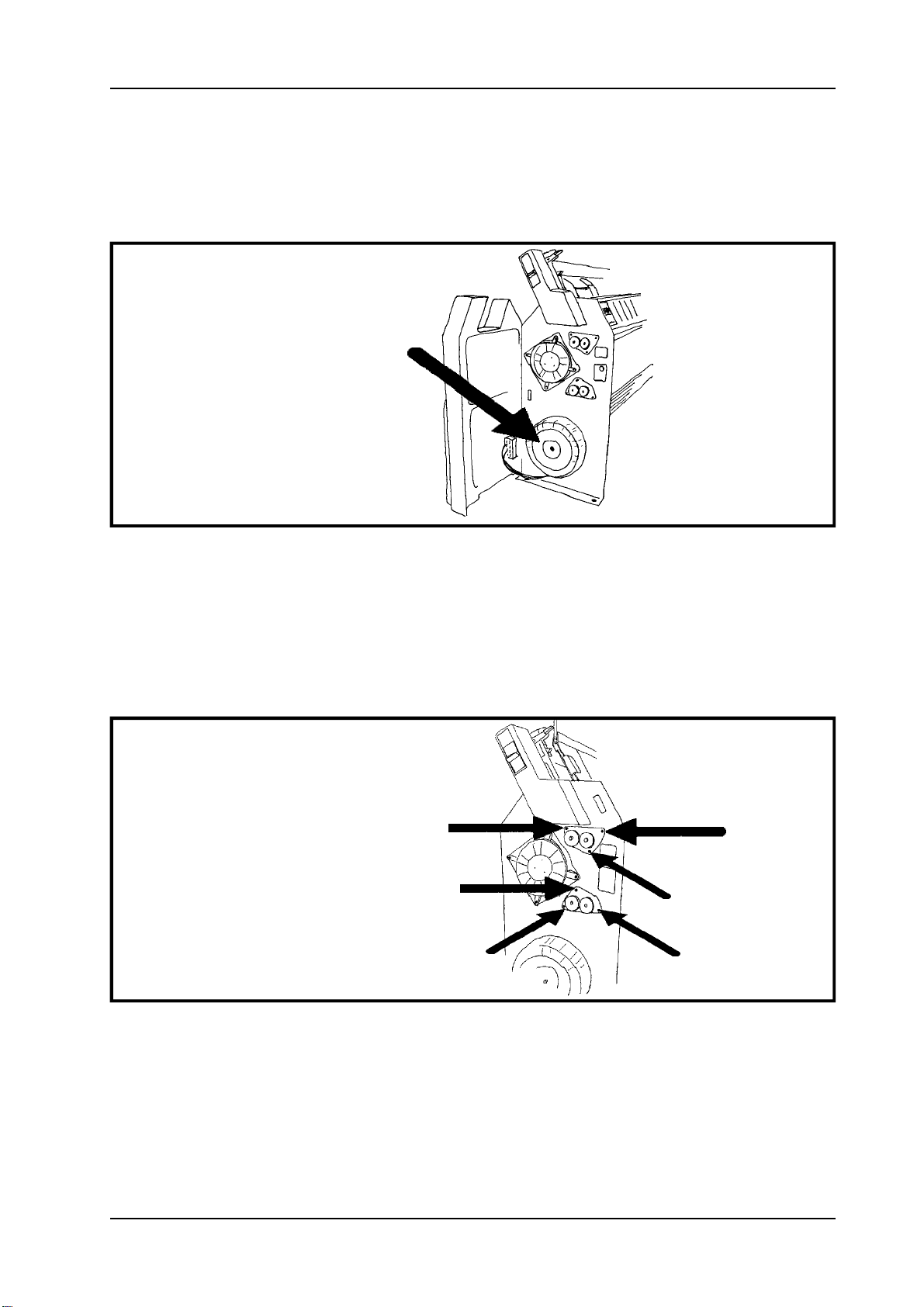
1.1.13 Driving belt 8
1.1.14 Pulleys 9
1.1.15 Right roll bearing 9
1.1.16 Roll axle 10
1.1.17 Printing head 10
1.1.18 Front panel board 11
1.1.19 Printing head board 11
1.1.20 Steering dowels 12
1.1.21 Plastic films 12
1.1.22 Hammers 13
1.1.23 Casing 13
1.1.24 Back bar 14
1.1.25 Rubber damper 14
1.1.26 Anvils 15
1.1.27 Axle 15
1.1.28 Gliding bearings 16
1.1.29 Stepper motor, printing head 16
1.1.30 Gear wheel, printinghead motor 17
1.1.31 Reference pulse sensor 17
1.1.32 Gear wheel, paper feeding 18
1.1.33 Sheet feeder 18
2. Service instructions 19
2.1 Adjust printing head
reference pulse offset 19
2.2 Internal printer test program 19
2.3 Front panel 19
2.4 Hammer configuration 20
2.5 Fault messages. 20
2.5.1 Failure "100" No reference-pulse 20
2.5.2 Failure "Front panel open". 20
2.5.3 Failure "Paper length fault". 20
2.5.4 Failure "Paper jam". 20
2.5.5 Failure "140". 20
2.5.6 Failure "150" 20
2.5.7 Failure "160" 20
2.5.8 Failure " 170" 21
2.6 Reference pulse offset. 21
2.7 Paper sensor adjustment 21
2.8 Voltage compensation. 21
2.8.1 Run Volt 21
2.8.2 Change parameters 22
2.8.3 Send file to Everest 22
3Printer modules 24
3.1 Screws nuts and glue 24
3.2 Printinghead 24
3.3 Chassis 24
3.4 Transmission 25
3.5 Shipping material 25
3.6 Electronics 25
3.7 Component locations 26
4Electronic components 31
4.1 Printinghead board 31
4.2 Main board 33
5Shematic descriptions 36
5.1 Mainboard layout 36
5.2 CPU 37
5.3 Memory map decoding 38
5.4 Dynamic Ram 39
5.5 EPROM & EEPROM 40
5.6 Stepper motor drivers -
printinghead interface 41
5.7 Keyboard Indterface &
Speech synthesis 42
5.8 Centronics interface 43
5.9 RS-232 44
5.10 Power supply 45
5.11 Printing head - paper indicator 46
5.12 Printing head - solenoid drivers 47
6Cables 48
6.1 Serial communication 48
6.1.1 RS232-C circuit summary. 48
6.1.2 Index RS232-C configuration 49
6.1.3 Cable INDEX IBM-PC 49
6.1.4 Cable INDEX-AT 49
6.1.5 Cable configuration
Index - Apple McIntosh 50
6.2 Centronics interface 50
6.2.1 Centronics inteface standard 50
7Disassembling flowchart 51

Version2.0
Page2IndexBraillePrinterCompany
INDEXEVERESTSERVICEMANUAL
1. Mechanics
1.1 Disassembling
Thismanualcontainsaflowchart,whichdescribestheeasiestwaytodisassembleandmakeserviceon
INDEXEverest-D.
Theflowchartislocatedinchapter6inthismanual.
TheflowchartfordisassemblingofINDEXEVEREST-Dwillbeusedinthefollowingway:
Lookforthedetailthatyouwanttodisassembleintheflowchart,forexampleanvils.
ByfollowingtheflowfromEVEREST-DtoANVILS.Youwillseethatyouhavetodothefollowing:
1.Openthefrontpanelcover.
2.Liftouttheprintinghead.
3.Removetheaxle.
4. Open the back bar.
5.Liftouttherubberdamper.
6.Removetheanvils.
1.1.1 Backplate
Figure 1.1.1 Disassembling of the back plate.
1.Unscrewthethreescrewsfromthefrontsideofthesheetfeeder.
2.Unscrewthefourscrewsonthebackplate.
3.Removethebackplate.
1.1.2 Expose the main board
Figure 1.1.2 Main board.

Version2.0
Page3
INDEXEVERESTSERVICEMANUAL
IndexBraillePrinterCompany
1.Unscrewthemarkedscrewsintheupperrawofthemainboard.
2.Turndownthemainboard.
1.1.3 Open the front panel cover
Figure 1.1.3 Opening the front panel cover.
1.Toopenthecover,grabthehandleandtheplasticcasing.
2.Openthefrontpanelcover.
1.1.4 Right casing

Version2.0
Page4IndexBraillePrinterCompany
INDEXEVERESTSERVICEMANUAL
Figure 1.1.4 Right casing.
1.Unscrewthemarkedscrews.
2.Slideoutthecasing.
1.1.5 Left casing
Figure 1.1.5 The left casing.
1.Unscrewthemarkedscrews.
2.Slideoutthecasing.

Version2.0
Page5
INDEXEVERESTSERVICEMANUAL
IndexBraillePrinterCompany
1.1.6 Remove the main board
Figure 1.1.6 Main board.
1.Loosentheflatcables.
2.Unscrewtheboard.
3.Takeoutthemainboard.
1.1.7 Loosen the front panel cover
Figure 1.1.7 Disassembling of the front panel cover.
1.Loosentheflatcablefromtheswitchpanel.
2.Unscrewthescrewsfromthesideplates.

Version2.0
Page6IndexBraillePrinterCompany
INDEXEVERESTSERVICEMANUAL
1.1.8 Fan
Figure 1.1.8 Location of the fan.
1.Loosentheconnectioncablestothefan.
2.Unscrewthefan.
3.Removethefan.
1.1.9 Front panel cover indicator
Figure 1.1.9 Front panel cover indicator.
1.Loosentheconnectioncablestothefrontpanelcoverindicator.
2.Slideouttheboard
.
3.Loosentheindicatorwithasolderingiron.

Version2.0
Page7
INDEXEVERESTSERVICEMANUAL
IndexBraillePrinterCompany
1.1.10 Transformer
Figure 1.1.10 Transformer.
1.Loosentheconnectioncablestothetransformer.
2.Unscrewthetransformer.
1.1.11 Roll bearing, left side.
Figure 1.1.11 Roll bearing.
1.Unscrewthethreescrewsontheupperrollbearing.
2.Carefullyremovetherollbearing.
Dothesameoperationfortheotherbearing.

Version2.0
Page8IndexBraillePrinterCompany
INDEXEVERESTSERVICEMANUAL
1.1.12 Stepper motor, paper feeding
Figure 1.1.12 Stepper motor, paper feeding.
1.Loosentheconnectioncablestothesteppermotor.
2.Loosenthefourscrewandremovethemotor.
1.1.13 Driving belt
Figure1.1.13 Locationofthedrivingbelt.
1.Pulloffthedrivingbeltfromthepulleys.

Version2.0
Page9
INDEXEVERESTSERVICEMANUAL
IndexBraillePrinterCompany
1.1.14 Pulleys
Figure1.1.14 Pulleys.
1.Removethepulleyswithapuller.
1.1.15 Right roll bearing
Figure 1.1.15 The right roll bearing.
1.Unscrewtheupperrollbearing.
2.Carefullyremovetherollbearing.
Dothesameoperationfortheotherbearing.

Version2.0
Page10 IndexBraillePrinterCompany
INDEXEVERESTSERVICEMANUAL
1.1.16 Roll axle
Figure 1.1.16 Roll axles.
1.Whentherollbearingisremoved,carefullyslideouttherollaxles.
1.1.17 Printing head
Figure 1.1.17 Printinghead.
1.Unscrewthefournutsonthescrewsholdingtheprintinghead.
2.Carefullypullouttheprintinghead.
3.Loosenthetwoflatcablesandthegroundconnectioncable.
Indice
Altri manuali Index Stampante


