
Innon Core IO - CR-IO-40MULTI Manuale utente

Core IO - CR-IO-40MULTI
User Manual
40 Point Mudbus I/O Module I6 DI, 8 DO, 8 UI, 8 UO/DI

2
Core IO 40 Multi Manual
1.0 4/10/2021
Get help at http://innon.com/support
Learn more at http://know.innon.com
innon.com
TABLE OF CONTENTS
INTRODUCTION 3
This Core IO model 3
HARDWARE 4
Wiring Power Supply 4
Wiring Digital Inputs (DI) 5
Wiring Universal Inputs (UI) 5
Wiring Universal Outputs (UO) - Including Use as Digital Input 5
Wiring Digital Outputs (DO) 5
Wiring the RS485 Network 6
Front LED Panel 7
CONFIGURE I/O 9
Digital Inputs 9
Digital Outputs (Relay) 9
Universal Inputs 10
Universal Outputs (Digital Inputs) 11
Pulse Counting 11
CONFIGURING THE DEVICE 13
Fixed Settings 13
DIP Switch Setting 13
Bluetooth and Android App 16
Ethernet Port and Web Server Conguration (IP version only) 18
Watchdog 19
BEMS POINT LISTS 20
Modbus Register Types 20
Input and Output Scaling 21
Modbus Register Tables 22
BEMS POINT LISTS 31
Drawings 33
Specications 34
Guidelines for Disposal 35
3
1.0 4/10/2021
Get help at http://innon.com/support
Learn more at http://know.innon.com
Core IO 40 Multi Manual innon.com
3
INTRODUCTION
Overview
In many installations, having cost-eective, robust, and simple hardware becomes a key factor in
winning a project. The Core range provides the perfect solution to meet these criteria. Innon have
collaborated with Atimus, a company with a wealth of experience in the eld, and are proud to
present Core IO!
The 40 MULTI is a 40 point I/O device providing a perfect balance of analogue and digital inputs
and outputs. The device supports a variety of sensor types, allows the use of pulse counters and
integrates a watchdog to safely position its outputs in case of a network failure.
BEMS communication is based on the robust and well-proven Modbus RTU over RS485 or Modbus
TCP (IP model only).
The conguration of the device can be achieved through the network using either the web interface
(IP version only) or Modbus conguration registers or by using an Android device and connecting
over Bluetooth using the dedicated app.

4
Core IO 40 Multi Manual
1.0 4/10/2021
Get help at http://innon.com/support
Learn more at http://know.innon.com
innon.com
HARDWARE
Overview
The CR-IO-40MULTI-RS only comes with the RS485 port, while the CR-IO-40MULTI-IP comes with
both RS485 and IP ports.
Both models come with Bluetooth on-board, so conguration can be achieved using an Android
device and the dedicated app. The IP CR-IO-40MULTI-IP model also integrates a web server
conguration interface, accessible via a PC web browser.
Wiring Power Supply
AC (24Vac) DC (24Vdc)
This Core IO model
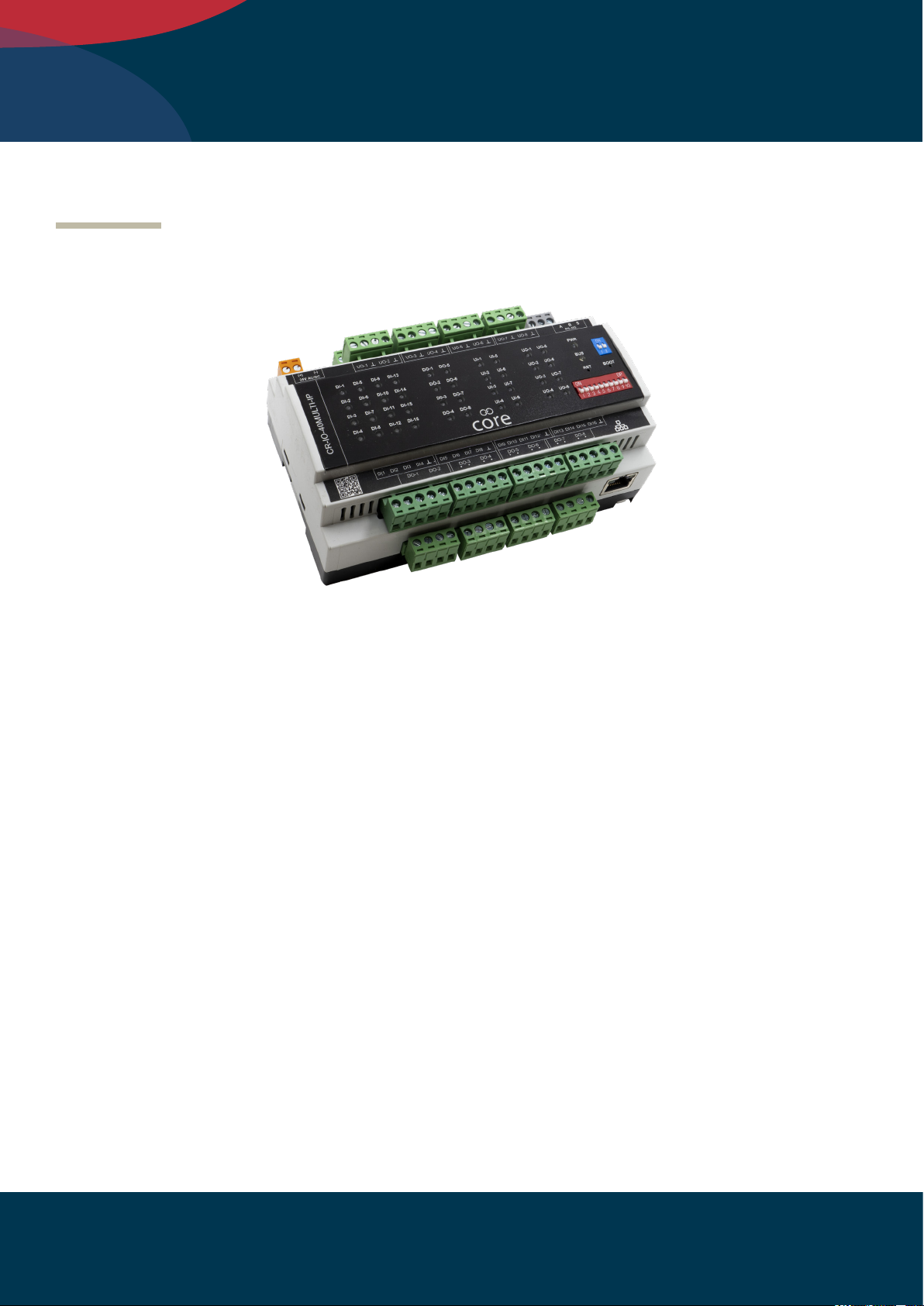
The CR-IO-40MULTI-RS and the CR-IO-40MULTI-IP modules come with 8 universal inputs, 8 universal
outputs, 16 digital inputs and 8 relay outputs.
Power
Universal inputs
I/O Channel Status LEDs
Digital Inputs
Digital Relay Outputs
Universal Outputs
Modbus serial comms
Power, comms
status LEDs
End-of-line/bias
Slave address/baud rate
Ethernet RJ45 port
5
1.0 4/10/2021
Get help at http://innon.com/support
Learn more at http://know.innon.com
Core IO 40 Multi Manual innon.com
5
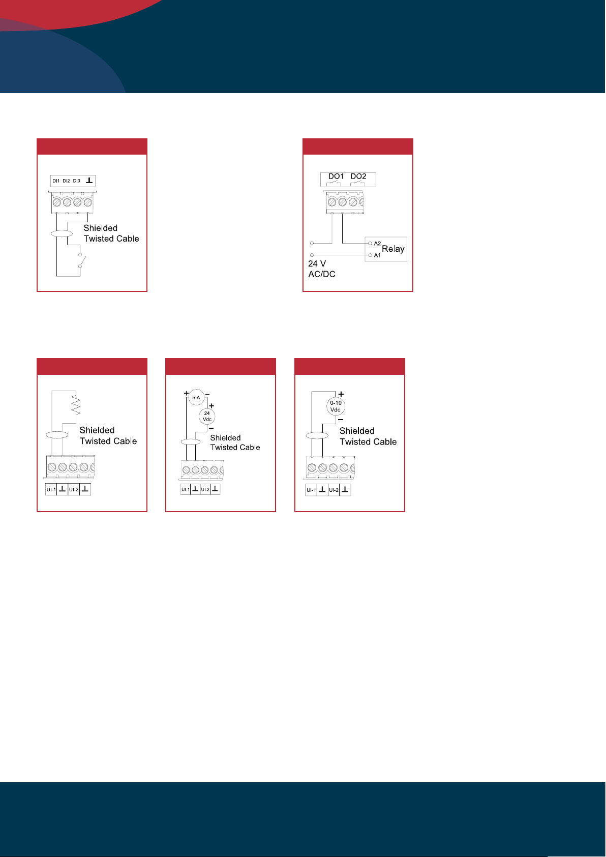
Wiring Digital Inputs (DI) Wiring Digital Outputs (DO)
Wiring Universal Inputs (UI)
Digital Input Relay out
Passive Sensor/Resistor Input 0/4-20mA 0/2-10v
Thermistor/
Resistor

6
Core IO 40 Multi Manual
1.0 4/10/2021
Get help at http://innon.com/support
Learn more at http://know.innon.com
innon.com
Wiring the RS485 network
12V DC Relay Digital Input
Some useful links to our knowledge base website:
How to wire an RS485 network
https://know.innon.com/howtowire-non-optoisolated
How to terminate and bias an RS485 network
https://know.innon.com/bias-termination-rs485-network
Please note - both IP and RS versions can use the RS485 port to respond to serial Modbus master
comms from the BEMS, but neither version can use the RS485 port to act as a Modbus master
or gateway.
RS485 to BEMS Master
Wiring Universal Outputs (UO) - Including Use as Digital Input
0-10V Output 0-10V actuator output example
7
1.0 4/10/2021
Get help at http://innon.com/support
Learn more at http://know.innon.com
Core IO 40 Multi Manual innon.com
7
Front LED Panel
The LEDs in the front panel can be used to get direct feedback on the status of the I/Os of Core IO
and more general information.
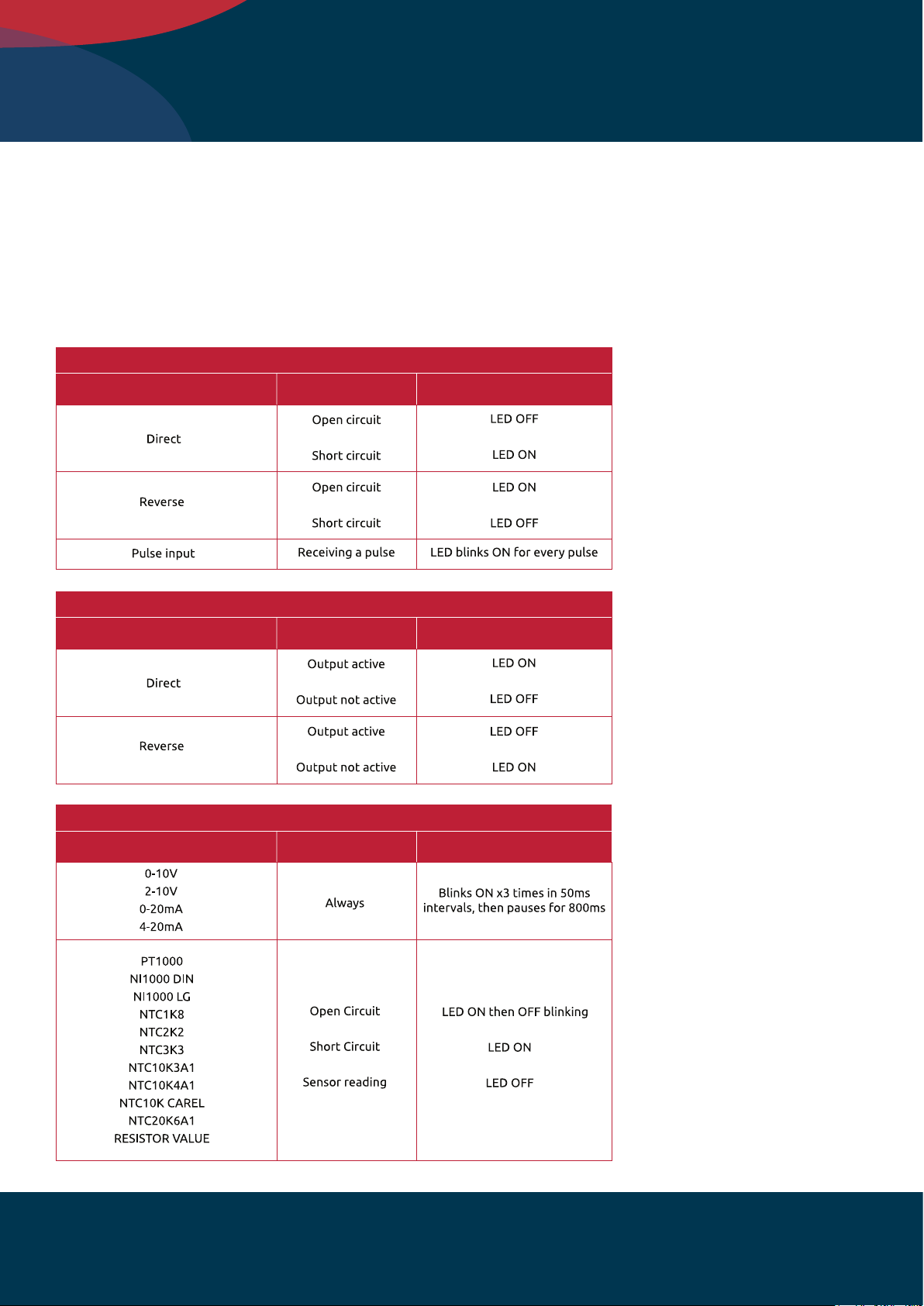
Below are some tables that will help decode each LED behaviour –
DI 1 to 16
Digital Input Mode Conditions LED Status
UI 1 to 8
Digital Input Mode Conditions LED Status
DO 1 to 8
Digital Output Mode Conditions LED Status

8
Core IO 40 Multi Manual
1.0 4/10/2021
Get help at http://innon.com/support
Learn more at http://know.innon.com
innon.com
UO 1 to 8
Input/Output Mode Conditions LED Status
BUS and PWR
LED Conditions LED Status

9
1.0 4/10/2021
Get help at http://innon.com/support
Learn more at http://know.innon.com
Core IO 40 Multi Manual innon.com
9
Digital Inputs
Digital Inputs can have a clean/volt free contact connected to Core IO to read its open/closed status.
Each digital input can be congured to be either:
• Digital Input direct
• Digital Input reverse
• Pulse input
While the “direct” and “reverse” mode would basically return status “False (0)” or “True (1)” when
the contact is either open or closed, the third mode “pulse input” is used to return a counter value
increasing by 1 unit every time the digital input closes.
A dedicated chapter on the pulse input topic is available later in this manual.
The pulse input can count eectively up to a frequency of 100Hz, with 50% duty cycle.
Digital Outputs (Relay)
The Digital Outputs are driven by relays.
Each Digital Output can be congured to be either:
• Digital Output direct
• Digital Output reverse (eectively reversing the logic of the output status)
For every Digital Output it is possible to congure the desired status when the “Watchdog”
function is triggered (BEMS oine for over a timeout delay).
CONFIGURE I/O

10
Core IO 40 Multi Manual
1.0 4/10/2021
Get help at http://innon.com/support
Learn more at http://know.innon.com
innon.com
Universal Inputs
Universal Inputs are used to connect analogue signal inputs to Core IO.
A variety of sensors and signals can be connected to a Universal Input. In terms of active signals,
both voltage (0-10V, 2-10V) and current (0-20mA, 4-20mA) are supported directly. As for passive
sensors, a long list of dierent thermistor types is available, on top of the direct resistance reading
(in case you prefer to run the conversion to temperature in the BEMS strategy for dedicated types
of sensors)
Here is a list of the supported input types for each individual Universal Input:
• Analogue Input 0-10V
• Analogue Input 2-10V
• Analogue Input 0-20 mA
• Analogue Input 4-20 mA
• PT1000
• NI1000 DIN
• NI1000 LG
• NTC1K8
• NTC2K2
• NTC3K3
• NTC10K3A1
• NTC10K4A1
• NTC10KCAREL
• NTC20K6A1
• Resistor Value
Indice
Altri manuali Innon Sistema I/O


Manuali Sistema I/O popolari di altre marche

WAGO
WAGO 750-344 Manuale utente

Teknim
Teknim TWM-1887 Manuale di istruzioni

Intelligent Appliance
Intelligent Appliance IA-2662-E Manuale utente

BERGHOF
BERGHOF ECC DIO 16/16 Manuale di istruzioni

Advantech
Advantech PCM-27J3AU Manuale di installazione e funzionamento

Festo
Festo CP-E08-M12-CL Manuale utente


