Intermatic IPURE Manuale utente

This manual must be given to the homeowner to ensure warranty coverage.
When installing and operating this Product and other associated equipment, basic safety precautions should
always be followed, including the following:
1. DO NOT OPEN THE GENERATOR BOX – NOT A SERVICABLE UNIT
2. READ AND FOLLOW ALL INSTRUCTIONS
3. Disconnect all AC power before installation.
4. WARNING – To reduce the risk of injury, do not permit children to use this product.
5. This Control must be installed by a qualified electrician, according to National and Local Electrical Codes.
6. The Control Box must be mounted vertically on a flat surface and a minimum of 5 ft (1.5m) horizontal
distance (or more, if local codes require) from the pool/spa
IMPORTANT SAFETY INSTRUCTIONS
READ, FOLLOW AND SAVE THIS INSTRUCTION MANUAL
Intermatic Incorporated, 7777 Winn Road, Spring Grove, IL 60081
Questions concerning your Salt Chlorine Generator? Call 321-274-0059 or 815-675-7000
The Natural Way To Purify Your Pool or Spa
PE25K120V
PE25K240V 25,000 gallons
40,000 gallons
PE40K120V
PE40K240V

Table Of Contents
Section 1. General Information...........................................................................1
Section 2. Important Safety Information ............................................................1
Section 3. Installation Instructions......................................................................2
3.1 General Information.................................................................2
3.2 Plumbing Your System ............................................................3
3.3 Installing the Cell.....................................................................4
3.4 Installing the Flow Sensor........................................................5
3.5 Mounting the Control Box .......................................................5
3.6 Wiring the Control Box............................................................7
3.7 Wiring the Flow Sensor............................................................8
Section 4. Startup Instructions............................................................................8
4.1 Before Adding Salt...................................................................8
4.2 Adding Salt...............................................................................9
4.3 Acceptable & Unacceptable Salts ............................................9
4.4 Salinity Demand Table.............................................................10
4.5 Calculating the Size of the Pool...............................................10
Section 5. Operating Instructions........................................................................11
5.1 Chlorinator Specifics................................................................11
5.2 Filtration...................................................................................11
5.3 Sanitation/Oxidation.................................................................11
5.4 Basic Operation........................................................................11
5.5 Winterizing...............................................................................12
5.6 Spring Startup...........................................................................12
5.7 Controls....................................................................................13
-Red Light ...............................................................................13
-Power Meter...........................................................................13
-On/Off Light ..........................................................................13
-Flow Light..............................................................................13
-Salinity Indicator....................................................................14
-Power Switch.........................................................................14
Section 6. Maintenance / Cleaning .....................................................................15
6.1 Cell Maintenance......................................................................15
6.2 Cell Cleaning............................................................................15
-Cleaning with optional cleaning cap......................................15
-Cleaning without optional cleaning cap.................................16
6.3 Understanding the chemistry....................................................17
6.4 Calculating Saturation Index....................................................19
Section 7. Troubleshooting.................................................................................20
Section 8. Warranty & Registration....................................................................24

Page 1
Section 1. General Information
Congratulations on the purchase of your new Salt Chlorine Generator. Your
purchase will minimize the efforts needed to maintain your pool and maximize your
enjoyment for many years. Before installation or operation, please read these
instructions carefully. This manual contains easy to follow step-by-step procedures
to properly install and operate your system. A little time spent understanding your
system and its parts will assure successful, trouble-free installation and usage.
When working around your pool, please take care to avoid hazards such as
electrical wires and chemicals. CAUTION! Safety comes first!
Section 2. Important Safety Instructions
WARNING
DANGER
READ AND FOLLOW ALL INSTRUCTIONS
All electrical work must be performed by a licensed electrician and conform to all national, state,
and local codes. When installing and using this electrical equipment, basic safety precautions should
always be followed, including the following:
DO NOT OPEN THE GENERATOR BOX – NOT A SERVICABLE UNIT
DISCONNECT ALL AC POWER BEFORE INSTALLATION
WARNING
To reduce the risk of injury, do not permit children to use this product.
WARNING
The Control Box must be mounted vertically on a flat surface and a minimum of 5 ft (1.5m)
horizontal distance (or more, if local codes require) from the pool/spa.
WARNING
The power cable must be hardwired to the time clock so that the system cannot operate without
the pump.

In Canada and some other regions, local codes require the unit be connected only to a circuit
that is protected by a ground-fault circuit-interrupter (GFCI). The installer should provide this
GFCI requirement. The GFCI should be tested on a regular basis by pushing the test button. If
the GFCI fails to operate correctly, there is ground current flowing indicating the possibility of
an electric shock. Do not use this unit. Disconnect unit and have a qualified professional correct
the problem before using.
CAUTION
SAVE THESE INSTRUCTIONS
WARNING
A Build-up of flammable fumes can result in a hazardous condition if the Cell is allowed to
operate without flow. This machine must be operated only with an approved in-line flow sensor.
The flow Sensor must be installed between the last piece of apparatus and the Cell, upstream of
the Cell.
CAUTION
DANGER
ALWAYS ADD ACID TO WATER, NEVER WATER TO ACID
Section 3. Installation Instructions
Section 3.1 General Information: The system comes in three sections, the Control
Box, cell and Flow Sensor. They are manufactured from the latest corrosion resistant
materials to give you years of trouble free use, and installing them in the most sheltered
position from sun and water will protect them from extreme weather conditions for years
to come.
Safety Measures
1. Only operate the system with an approved flow sensor.
2. See safety measures and warnings on page 2 of this manual.
Additional Materials Required
1. PVC solvent cement and priming fluid
2. Hacksaw or pipe cutters
3. Screwdrivers
4. Drill
5. Teflon Tape (a.k.a. Plumber’s Tape)
6. Silicone Sealant (DO NOT USE silicone glue or petroleum jelly).
7. Pipe adaptors (i.e. reducer couplings) if needed for systems with 1 ½ inch plumbing.
Page 2

Page 3
Section 3.2 Plumbing Your System
MODEL CONFIRMATION: Confirm you have the
correct model for your pool size by checking the model
number on the cell:
•PE25K < 25,000 gallons (100,000 liters)
•PE40K < 40,000 gallons (150,000 liters)

Page 4
Section 3.3 Installing the Cell
NOTE
Lay out equipment pieces to be sure there is enough pipe space between the last piece of apparatus and
the tees in the return line to fit the Flow Sensor and the Cell. A Vertical Installation may be used to save
space.
1. The Cell and Flow Sensor must be installed
downstream from the filter and heating
devices but before any tees in the return
line. The Cell may be installed horizontally
or vertically so long as the Cell is pointed in
the direction of flow and is installed
immediately after the enclosed Flow Sensor
(see diagram above).
2. Approximately 15 inches (~380 mm) of available pipe length will be needed for horizontal
installations of the Flow Sensor and Cell. Vertical installations can be made to take less space.
3. On the pipe where the cell will be installed, mark two lines 11 3/4 inches (300mm) apart and cut out
using hacksaw or pipe cutters.
4. Unscrew and remove the barrel unions (i.e. barrel nuts and slip connections) from either end of the
Cell. Thread one of the barrel nuts over the pipe and glue its slip connection to the cut pipe.
5. Hold up the Cell with the second union to gauge the proper distance before threading the second nut
and gluing the second slip.
6. After the glue had sufficient drying time, place the Cell with the o-rings into the opening between
the two ends of the pipe and tighten the unions making sure that the Cell is installed with the arrow
pointing in the same direction as the flow (i.e. water should enter from the side with the blue cap).
Flow direction

Section 3.4 Installing the Flow Sensor
1. Install the Flow Sensor between the last piece of apparatus and the Cell (if installed after the Cell,
damage to the sensor may result). When possible, install on a horizontal pipe.
2. Mark two lines on the pipe 3inches (~76 mm) apart and cut with a hacksaw or pipe cutters.
3. Clean and glue the “T” connector (included) to the pipe making sure that the threaded end with the
sensor is on the topside of the pipe.
4. Be sure the arrow on the top of the Flow Sensor is pointing in the direction of flow, and that no glue
touches the paddle inside the sensor as it may cause it to jam.
Page 5
Flow direction
Section 3.5 Mounting the Control Box
1. It’s important to identify and understand the
purpose of each cord at the bottom of your
Control Box. Please refer to the picture for cord
identification and application prior to mounting:
BONDING – Bonding is recommended and may
be required by local code. The bonding lug is
found on the bottom of the Control Box.
POWER CORD – Hardwire the power cable to
the time clock as indicated in the section titled
“Wiring the Control Box”. Check label on side of
Control Box for the proper voltage specification
of your system (i.e. 120v or 240v)
FLOW SENSOR – The flow switch MUST BE
connected to the Control Box in order for the
system to work properly. Ensure proper flow
switch operation once installed.
CELL CONNECTORS – Connect the two black
wires from the Control Box to the two metal studs
on the sides of the Cell and tighten firmly with a
screwdriver by hand. See “Wiring the Control
Box” for further instructions.

Page 6
Section 3.5 Mounting the Control Box (Continued)
2. The Control Box must be mounted vertically on a flat surface and a minimum of 5 ft (1.5m)
horizontal distance (or more, if local codes require) from the pool/spa.
3. Locate a position for your Control Box within 10 ft (~3 meters) of where the Cell will be installed
and within 2 ft of the power supply to ensure enough wire is available.
All four sides of Control Box
must have air ventilation for
proper heat dissipation.
4. Because the box acts as a heat sink dispersing heat from
inside the box, do not block the four sides of the Control
Box. Do Not mount the system inside a panel or tight
enclosed area.
WARNING
5. Secure the hanging rack on the wall using the enclosed
screws and anchors. 1/4” (8mm) drill bit should be used for
the anchor holes.
6. Hang the Control Box on the mounted hanging rack.
7. Hardwire the power cable to the time clock as
indicated in the wiring instructions below.
*Check the label on the side of the Control Box
for the proper voltage specification on your
system (i.e. 120v or 240v).
8. Do not extend the cable leading to the cell. This
decreases the system’s efficiency and will void
warranty coverage. Please contact the
manufacturer for installations demanding a
longer cell cable.

Section 3.6 Wiring the Control Box
1. Attach the green ground wire to the grounding lug or bar.
2. Connect the black Load wire from the chlorine generator to
Load 1 of the time clock.
3. If wiring a 240 Volt generator, connect the third wire to Load 2
of the time clock. If wiring a 120 Volt generator, connect the
third wire to the Neutral lug or bar on the timer (see label on the
left side of the Control Box to confirm voltage).
4. Bonding is recommended and may be required by local code.
The bonding lug is found on the bottom of the Control Box.
Page 7
Check whether your chlorine generator operates on 120 volts or 240 volts (see label on the left
side of the Control Box), and be sure to wire the system accordingly. It is critical to wire the
chlorine generator in such a way that it can only operate when the pump is operating (i.e. load
side). See instructions below for details.
CAUTION
5. Connect the two black wires from the Control Box to the two metal
studs on the sides of the Cell. These wires are interchangeable.
6. Tighten firmly by hand, with a screwdriver. To avoid damage to the
screws, DO NOT use a power screwdriver.
7. Push the plastic terminal covers up to cover the terminal connection
until they click into place. This will ensure a watertight connection.

Section 3.7 Wiring the Flow Sensor
Section 4. Startup Instructions
NOTE
Flow Sensor wires are interchangeable. You
must have flow sensor connected in order for
the Salt Chlorine Generator system to
work properly.
Section 4.1 Before Adding Salt
Balance the chemicals
See the section titled “Understanding the Chemistry” for recommended water balance. Also, add 1
quart of metal remover and 1 quart of non-copper based algaecide to the pool, according to the
manufacturers instructions. This will ensure that the transition to the Natural Generator system will be
quick and trouble-free.
Measure existing salt in your pool.
Years of liquid chlorine use may cause the salt reading to be higher due to residual salt.
New Pools
Wait 10-14 days, or longer if specified by the pool builder, for plaster to cure before adding salt or
operating the I-Pure Salt Chlorine Generator.
Biguanide Pools
If installing on a pool using Biguanide sanitizers, all Biguanides must be removed before system startup.
Page 8
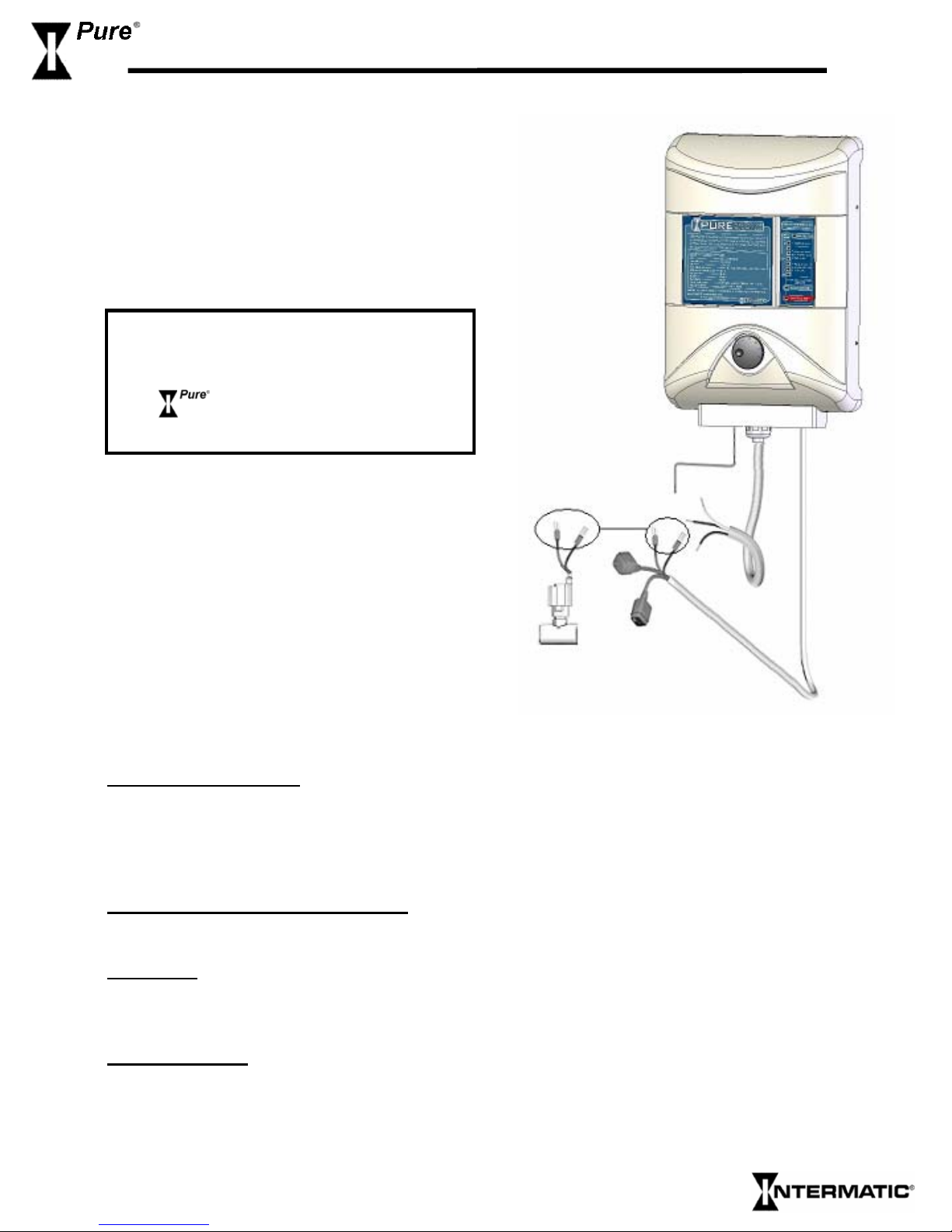
Flow Sensor
1. Find the two 18 AWG wires with the ¼” Quick connect
terminals from the Cell cable and push them on their
respective connectors on the Flow Sensor. These wires
are interchangeable.
Questo manuale è adatto per i seguenti modelli
4
Indice