iXsystems TrueNAS Mini Series Manuale

TrueNAS®Mini 3.0 Family
Basic Setup Guide
Version 1.1

Copyright © 2020 iXsystems, Inc. All rights reserved. All trademarks are the property of their respective owners.
TrueNAS units are carefully packed and shipped with trusted carriers to arrive in perfect condition. If there is any shipping damage
or any parts are missing, please take photos and contact iXsystems support immediately at [email protected] or 855-GREP4-
iX (855-473-7449) or 408-943-4100.
Please locate and record the hardware serial numbers on the back of each chassis for quick reference.
Contents
Introduction .................................................................................... 1
1 Become Familiar with the TrueNAS Mini Family ....................................... 2
1.1 The TrueNAS Mini E and E+ ................................................................... 2
1.2 The TrueNAS Mini X ............................................................................ 3
1.3 The TrueNAS Mini X+ .......................................................................... 4
1.4 The TrueNAS Mini XL+ ......................................................................... 5
2 Installing Hard Drives ...................................................................... 6
3 Removing Drive Trays ...................................................................... 7
4 Mini 2.5” Drive Bays ......................................................................... 7
4.1 Mini XL+ 2.5” Bay Installation ................................................................. 7
4.2 Mini X/X+ 2.5” Bay Installation ............................................................... 8
5 Connect Network and Power Cables .................................................... 9
5.1 Powering on the TrueNAS Mini .............................................................. 9
5.2 Console Setup on the TrueNAS Mini ......................................................... 9
6 Logging in to the TrueNAS Web Interface ............................................. 10
7 Additional Resources ..................................................................... 11
7.1 Contacting iXsystems ........................................................................ 11
Page 1
Introduction
The TrueNAS Mini Storage Appliance is built to support all the features of TrueNAS in various con-
venient form factors. The Mini E and E+ have four hot-swappable 3.5” drive bays. The Mini X and X+
have ve hot-swappable 3.5” drive bays and two 2.5” drive bays. The Mini XL+ has eight hot-swappa-
ble 3.5” drive bays and a single 2.5” drive bay.
TrueNAS Mini products share similar chassis and front panels, but have dierent system compo-
nents that can change what type of connections are available and where they are located. Each Mini
product has images that show where indicators and connectors are on that product. The warranty is
not aected by removing or cutting the Tamper Resistant sticker to remove the case.
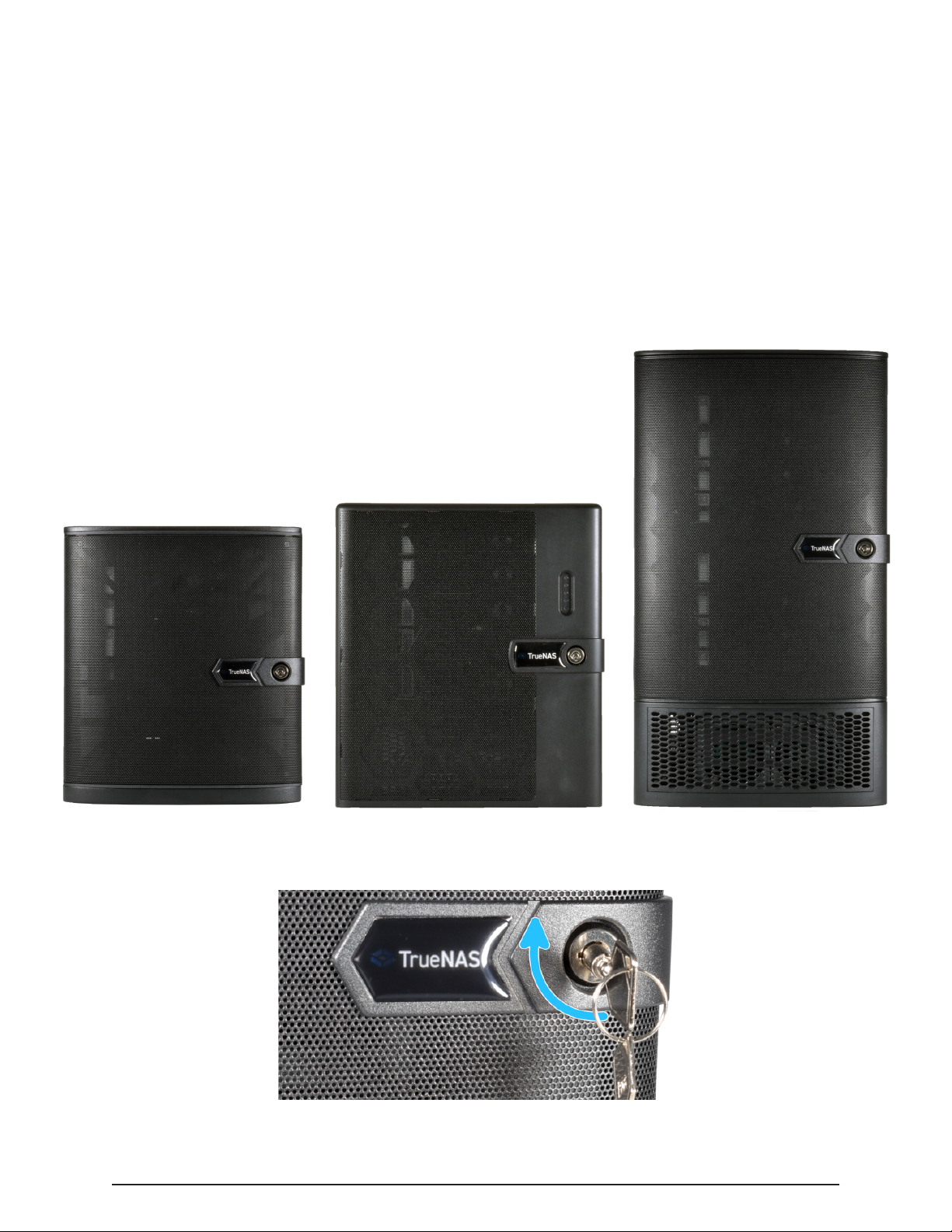
From left to right are the TrueNAS Mini E/E+, the TrueNAS Mini X/X+, and the TrueNAS Mini XL+ :
The drive bay door can be locked for added security. To lock the door, insert one of the door keys in
the lock and turn the key clockwise ninety degrees.

Page 2
1. Four hot-swap 3.5” drive bays,
2.5” drive adapters are optional
2. Power Button
3. Reset Button
4. Power Indicators
5. Disk Activity Light
6. Network Activity Indicator
7. Unit Identication Indicators
8. Two USB 2.0 ports
1 Become Familiar with the TrueNAS Mini Family
1.1 The TrueNAS Mini E and E+
1. Back Panel Power Connector
2. Serial Port
3. VGA connector
4. Four GbE network ports
5. IPMI remote management network
port
6. Port cover
7. One USB 3.0 port
The warranty is not aected by re-
moving or cutting the Tamper Resistant
sticker to remove the case.
1. Four 3.5” drive trays
2. Two Ethernet cables
3. One bag of HDD screws
4. One power cord
5. One set of keys

Page 3
1. Five hot-swap 3.5” drive bays,
2.5” drive adapters are optional.
2. Two 2.5” drive bays
3. Two USB 2.0 ports
4. Power Button
5. Reset Button
6. Power Indicators
7. Disk Activity Light
8. Network Activity Indicator
9. Unit Identication Indicators
1.2 The TrueNAS Mini X
1. Back Panel Power Connector
2. Serial Port
3. VGA connector
4. Four GbE network ports
5. IPMI remote management network port
6. Port cover
7. One USB 3.0 port
The warranty is not aected by removing or
cutting the Tamper Resistant sticker to remove
the case.
1. Five 3.5” drive trays
2. Two 2.5” drive trays and
screws
3. Two Ethernet cables
4. One bag of 3.5” HDD screws
5. One power cord
6. One set of keys

Page 4
1.3 The TrueNAS Mini X+
1. Back Panel Power Connector
2. IPMI remote management network port
3. Two USB 2.0 ports
4. Two 10 GbE network ports
5. VGA connector
The warranty is not aected by removing or
cutting the Tamper Resistant sticker to remove
the case.
1. Five 3.5” drive trays
2. Two 2.5” drive trays and
screws
3. Two Ethernet cables
4. One bag of 3.5” HDD screws
5. One power cord
6. One set of keys
1. Five hot-swap 3.5” drive bays,
2.5” drive adapters are optional.
2. Two 2.5” drive bays
3. One USB 3.0 port
4. One USB 2.0 port
5. Power Button
6. Reset Button
7. Power Indicators
8. Disk Activity Light
9. Network Activity Indicator
10. Unit Identication Indicators

Page 5
1. Eight 3.5” drive bays, 2.5” drive
adapters are optional
2. One 2.5” drive bay
3. Power Button
4. Reset Button
5. Power Indicators
6. Disk Activity Light
7. Network Activity Indicator
8. Unit Identication Indicators
9. One USB 3.0 port
10. One USB 2.0 port
1.4 The TrueNAS Mini XL+
1. Back Panel Power Connector
2. IPMI remote management network port
3. Two USB 2.0 ports
4. Two 10 GbE network ports
5. VGA connector
The warranty is not aected by removing or
cutting the Tamper Resistant sticker to remove
the case.
1. Eight 3.5” drive trays
2. One 2.5” drive tray and screws
3. Two Ethernet cables
4. One bag of 3.5” HDD screws
5. One power cord
6. One set of keys

Page 6
2 Installing Hard Drives
TrueNAS Minis support hard drives up to 14 TiB. Drives designed for Network Attached Storage
(NAS) are required. These drives run cooler and quieter than desktop drives. NAS hard drives are
available direct from iXsystems or retailers.
When ordered without hard drives, drive trays are shipped with ller inserts to protect them. If not
all bays will be lled with drives, keep the llers in the empty trays to protect them.
To mount a hard drive in a tray, remove the two rear screws holding the ller (1). Gently spread both
sides of the tray away from the ller (2) until the pins release (3), then remove the ller.
Starting with the top bay, gently insert a tray into a drive bay until it stops (1). Swing the latch closed
until it locks (2). Repeat for all hard drives to be mounted. Load trays with llers into any remaining
empty bays.
Place the hard drive into the tray (1) and mount the hard drive in the tray with four screws (2).
Drive tray buttons can be locked to prevent tray removal. The tray button is unlocked when
the slot is horizontal and locked when the slot is vertical. Lock a tray button by inserting a
at-head screwdriver into the slot in the center of the button and gently turn it ninety de-
grees clockwise so the slot is vertical.

Page 7
4 Mini 2.5” Drive Bays
4.1 Mini XL+ 2.5” Bay Installation
The Mini XL+ has a single additional 2.5” bay for an SSD.
To remove the tray, release the latch by sliding the button to the left (1). Gently swing the latch to
the right (2), then slide the tray out (3).
To add an SSD, unscrew the two attachment screws from the SSD tray underside and remove the
SSD tray ller (4). Attach the SSD to the tray with four screws from the bag labeled 2.5” through the
bottom of the tray (5).
Gently insert the tray into the bay until it stops (6) and the latch is nearly shut. Swing the latch closed
until it locks (7).
3 Removing Drive Trays
If a drive tray must be removed, release the latch by pushing the large circular button to the right (1).
Swing the latch to the left to eject the tray, then pull outwards on the latch to begin sliding the tray
out (2). Grip the top and bottom of the tray and gently remove it (3).

Page 8
4.2 Mini X/X+ 2.5” Bay Installation
The Mini X and X+ have two 2.5” sdd drive bays.
To remove the tray, release the latch by sliding the button to the left (1). Gently swing the latch to
the right (2), then slide the tray out (3). Remove the ller tray from the drive tray by removing the
screws (4), place the drive in the tray and secure the drive to the tray with the provided screws (5).
Follow the same process for both drive trays. To reinsert the the tray in the unit, follow the inverse
of the removal steps. Gently insert the tray into the bay until it stops (6) and the latch is nearly shut.
Swing the latch closed until it locks (7).
Questo manuale è adatto per i seguenti modelli
3
Indice
Altri manuali iXsystems Magazzinaggio

iXsystems
iXsystems TrueNAS ES12 Manuale

iXsystems
iXsystems TrueNAS 11.3-U5 Manuale utente

iXsystems
iXsystems TrueNAS Manuale

iXsystems
iXsystems TrueNAS F Series Manuale utente

iXsystems
iXsystems FreeNAS Mini Manuale utente

iXsystems
iXsystems TrueNAS M Series Manuale

iXsystems
iXsystems TrueNAS R50 Manuale

iXsystems
iXsystems TrueNAS R Series Manuale

iXsystems
iXsystems TrueNAS ES24 Manuale

iXsystems
iXsystems TrueNAS M Series Manuale


