JETStream DRILLJET PI-180 Foglio di istruzioni
Read these instructions thoroughly before installing, connecting, or using the
DrillJet™. If any questions remain, call JETSTREAM at (800) 231-8192 or (832) 590-
1300. Also read the yellow JETSTREAM SAFETY WARNING pamphlet included with
the shipment of your new DrillJet™ and reproduced inside this publication. This
product is sold with the understanding that the purchaser agrees to thoroughly
train all operators and maintenance personnel in the correct and safe installation,
operation and maintenance of the product and to provide adequate supervision of
personnel at all times. Retain these instructions for future reference. If this product
is resold or otherwise conveyed, purchaser must pass on the instructions to the
new user.
PRODUCT INSTRUCTIONS
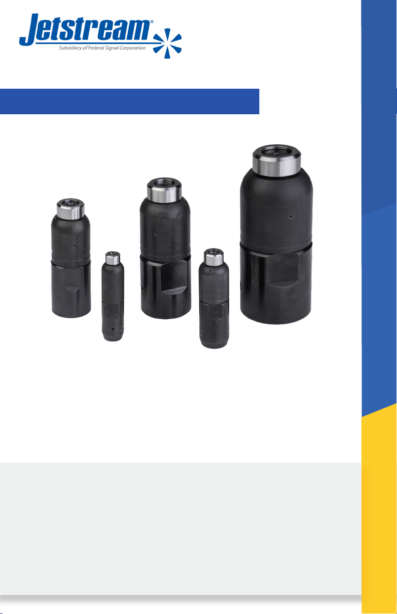
The DrillJet™ is a self-powered rotating nozzle designed for tube
cleaning available in ve sizes with a variety of inlet options. The
DrillJet™ is a universal type of tool with six or seven nozzles that
clear blockages, clean, and provide thrust to propel the tool down
the pipe. The tool is available in a range of pressures and ows
depending on size.
DRILLJET™
PI-180

2PI-180 January 2022
TABLE OF CONTENTS
Section 1: Safety ............................................................................................. 3
Section 2: Product Description ........................................................12
Section 3: Preparation for Use ..........................................................14
Section 4: Setup.............................................................................................15
Section 5: Operation...................................................................................16
Section 6: Service ......................................................................................... 17
Section 7: Troubleshooting................................................................... 17
Appendix A......................................................................................................... 18
Appendix B ....................................................................................................... 23
Warranty ............................................................................................................. 24
Scan or click
the QR Code for
more product
information.

3PI-180January 2022
SECTION 1: SAFETY
This information was prepared to aid in the identication of potentially
unsafe conditions when using high pressure waterblast equipment. It
should be noted that other potential hazards may exist which might
have not been mentioned in this brochure.
In all cases, JETSTREAM products are sold with the understanding that
the purchaser agrees to thoroughly train all operating and maintenance
personnel in the correct and safe installation, operation of maintenance
of waterblast equipment and to provide adequate supervision of
personnel at all times.
Read the following in its entirety before connecting, operating or
repairing equipment. Purchasers and operators also should be familiar
with the current version of the “Industry Best Practices for the Use
of High Pressure Waterjetting Equipment” published by the Waterjet
Technology Association, as well as any applicable OSHA regulations,
standards and guidelines.
Should any questions arise concerning safe and proper procedure,
contact JETSTREAM prior to the installation or use at (800) 231-8192 or
(832) 590-1300.
Incorrect Use of High Pressure Waterblast
Equipment May Cause Serious Injury
Read these instructions in their entirety
before using any JETSTREAM products.

4PI-180 January 2022
GENERAL WATERBLAST
1. Use only clear, clean water in high pressure system.
2. Place barricades with warning signs or barricade tape around work
area.
3. Outt all operators with Personal Protective Equipment (PPE).
Hard hat with plastic face shield, rainsuit, non-skid knee boots with
metatarsal protection, gloves, ear protection and body armor rated for
operating pressures are considered minimum safety equipment. Proper
respiratory protection is required where dangerous fumes or dust is
present or created by the waterblasting operation. Follow applicable
OSHA regulations, standards and guidelines regarding the use of
respiratory protection if harmful fumes or dust is present during, or
created by the waterblasting operation.
4. Use products intended for high pressure waterblasting only.
5. No product should be altered without written consent of the
manufacturer.
6. Read and follow all manufacturer’s instructions prior to using any
waterblast product. Contact manufacturer.
7. Thoroughly review alternative methods before initiating any
potentially dangerous waterblasting operation. Fully automated, semi-
automated, and/or mechanized methods should all be considered rst.
Contact the applicable waterblasting manufacturers for assistance and
recommendations.
8. The operator handling the cleaning device (with nozzle) must always
have control of water pressure. A surface cleaning operator should
operate a trigger style control gun capable of instantaneously stopping
pressure to nozzle. A tube cleaning lance operator should operate a foot
gun capable of instantaneously stopping pressure to the lance.
9. Inspect the condition of all components prior to use. Use no items
which are in questionable condition.
10. Check the condition of thread connections prior to the make-up of
any high pressure connection. Use Teon tape and anti-seize on male
pipe (NPT) thread for sealing purposes. Do not let tape overlap the male
pipe thread end. Tape fragments may enter system water stream and
clog nozzle’s orices.
Do Not use a component with missing or damaged threads on the
high pressure connections.

5PI-180January 2022
11. Properly tighten all high pressure connections. All NPT connections
must have a minimum engagement of four (4) threads. Pipe (NPT)
connections should be made up hand tight plus two (2) full wrenched
turns. Do not tighten NPT threads past two (2) wrenched turns.
Use wrench ats (when available) or a properly adjusted
smooth jaw plier wrench (JS PN 64119) for tightening components.
Avoid using pipe wrench as wrench marks will cause high pressure
components to crack and fail.
12. All high pressure hose connections require a hose restraint (whip
check), including connection at uid end discharge.
13. Before attaching a nozzle to the control gun or tube cleaning lance,
operate the pump at low speed to purge dirt and debris from system.
Dirt and debris can clog nozzle orice(s) and cause excessive
system pressure which could lead to a lance failure.
14. With nozzle installed, operate the pump at a low speed (low
pressure) for test. Should system repairs or adjustments be necessary,
stop pump and relieve all pressure before making required repairs or
adjustments. The pump operator should watch the nozzle operator
at all times in case any difculty arises and it becomes necessary to
depressurize system. If the pump operator does not have a clear line
of sight to the nozzle operator, it may be necessary to have another
employee available to communicate between the nozzle and pump
operators.
15. With the system operating properly, increase pump speed
slowly until operating pressure is reached and adjusted. Pressure
adjustments should always be made slowly. The nozzle operator shall
be warned before any pressure adjustment is made by the pump
operator. A sudden change in reaction force may cause the nozzle
operator to lose balance.
16. Use minimum pressure required for cleaning. Do not exceed the
operating pressure of the system’s lowest pressure-rated component.
All equipment pressure rating markers and warning tags should be left
intact.
17. Waterblast operators must be made aware that the cleaning
nozzle’s discharge jets(s) can inict serious body wounds.
Supervisors should demonstrate the potential danger of discharge
jet(s) by showing all new operators the effect of a waterjet by cutting a
scrap piece of wood such as a 2” x 4”.

6PI-180 January 2022
18. If equipment malfunctions or a system malfunction is suspected,
immediately stop cleaning activity and relieve the pressure in the
system before attempting any repairs. Always follow the manufacturer’s
repair instructions.
19. Only trained persons should be authorized to perform any
maintenance or repair.
20.Following any repairs, the system should be operated at low pressure
for test. Bring equipment up to operating pressure slowly.
21. For shutdown in freezing conditions, even for brief periods, drain
water from all components. Prior to starting operations in freezing
conditions, the operation of all equipment components must be
checked carefully to make sure components are not frozen and can be
operated.
22.Store components properly by protecting them from damage when
not in use. Be sure all safety warning tags and markers remain intact.
PRESSURE RELIEF DEVICES
1. Read General Safety section prior to installing Relief Valve and/or
Pressure Relief Devices.
2. A waterblast system should include both primary and secondary
pressure relief protection:
A. For primary protection a primary rupture disc assembly or spring-
loaded relief set at 1.2 times, maximum operating pressure is
recommended (i.e. relief valve is set at 12,000 psi if maximum
operating pressure is 10,000 psi)
B. For secondary protection a rupture disc assembly containing a
manufacturer’s approved disc having a burst rating of 1.4 times
maximum operating pressure is recommended.
Only use a rupture disc holder which will NOT permit the
use of coins or other objects in place of discs.
3. Relief devices should never be mounted so the discharge could
strike personnel.
4. Never install a shut-off valve between the pump and relief device.
5. “Set pressure” must be prominently displayed on all relief devices.
Never install or use a relief device unless its “set pressure” is known.

7PI-180January 2022
6. Do not attempt to correct a leaking relief valve by increasing spring
tension as this will increase its set pressure.
7. Do not use a pressure relief valve as a combination relief and
throttling device.
8. Keep relief valve dry during freezing conditions.
NOTE: Pressure relief devices are imperative for the protection of
both operator and equipment from dangerous over-pressurization.
HIGH PRESSURE HOSE
1. Read General Safety section prior to connecting high pressure hose.
2. Do not use a high pressure hose with a burst rating less that 2.5
time the pressure at which it will operate. 10,000 psi operating pressure
high pressure must have a minimum 25,000 psi burst rating. 8,000 psi
operating hose must have a minimum 22,000 psi burst rating.
3. Do not use a high pressure hose that has an unknown burst rating
or manufacturer’s operating pressure rating.
4. Use of a Safety Shroud is strongly recommended for added safety
where hose connects to control gun.
5. Use of hose restraint (whip check) is required at all hose
connections, including connections at uid end.
6. Always apply wrench to wrench ats when making threaded
connections. Do not apply wrench on the end tting ferrule (collar).
7. Remove hose from service if:
A. Cover is damaged and reinforcing wires are exposed to rust and
corrosion;
B. Cover is loose, has blisters or bulges;
C. Hose has been crushed or kinked;
D. End tting shows evidence of damage, slippage, or leakage.
E. Hose has been exposed to pressures greater than 50% of burst
rating; or
F. Hose is three or more years old, regardless of condition.
8. Disconnect, drain, coil and store hose properly after use.
9. Never attempt to repair or recouple high pressure hoses in eld. High
pressure hose end ttings are the permanently crimped type and can
8PI-180 January 2022
only be properly installed with hydraulic crimping equipment.
NOZZLES
1. Read General Safety section.
2. Nozzle ow ratings must be compatible with pump discharge and
pump pressure rating. (See Nozzle Flow Rating Chart on page 18.)
3. Use only nozzles with a manufacturer’s pressure rating of at least
the operating pressure or a burst rating or no less than 3.0 times the
desired operating pressure.
4. Prior to installation, make sure the nozzle has no clogged orices.
5. Apply 3 - 4 wraps of Teon tape to male connection threads on the
nozzle. Apply anti-seize compound over the sealant tape for additional
protection against galling in connection threads. Wrench connection 1
1/2 - 2 turns past hand tight. A minimal thread engagement of four (4)
threads should exist on all Jetstream NPT pipe connections.
6. Use wrench ats (when available) or a properly
adjusted smooth jaw plier wrench (JS PN 64119) to tighten nozzle. Avoid
using pipe wrench as wrench marks will cause nozzles to crack and fail.
7. Blocked orice(s) can cause excessive system pressure and failure.
If orice(s) appear clogged or partially blocked with dirt or debris,
remove nozzle from J-Force and clean immediately.
8. Remove nozzle from service if:
A. Nozzle is split or damaged;
B. Nozzle sidewall is worn by more than 25% at any point;
C. Nozzle’s ability to hold pressure is questionable
D. Threads are missing or damaged
FLEXIBLE TUBE CLEANING LANCES
1. Read General Safety section and Nozzle Safety Warnings prior to
connecting ex lances.
2. Do not use a ex lance with a burst rating less than 2.25 times
the pressure at which it will operate. 10,000 psi operating pressure
ex lances must have a minimum 22,000 psi burst rating. 8,000 psi
operating pressure ex lances must have a minimum 18,000 psi burst
rating.

9PI-180January 2022
3. Do not use a ex lance that has an unknown burst or unknown
manufacturer’s operating pressure rating.
4. Never use a lance which is kinked, worn, frayed or whose abilities
to hold pressure is questionable.
5. Do not use a lance which has damaged or missing threads.
6. Clearance between lance and tube deposits must be sufcient to
allow unrestricted backow of water and debris. With tubes containing
hard deposits this clearance should be 1/8” minimum on the diameter
(or 1/16” per side) of the lance. With tubes containing soft, pliable
deposits this clearance should be greater. Insufcient side clearance
may cause lance to blow back toward operator.
7. Serious injury may occur should a lance with live
nozzle exit tube. Use anti-withdrawal device to prevent lance from
exiting tube unexpectedly.
8. The following JETSTREAM lance accessories are strongly
recommended for safer lance operation:
A. Lance Strain Relief - Helps prevent lance inlet end tting failure.
B. Lance Stinger - Affords the operator greater control of nozzle.
Establishes a “safety zone” so operator knows when nozzle is about
to exit tube; will eliminate possibility of nozzle and lance “double
back” toward operator within large diameter pipe.
C. Anti-withdrawal device prevents the lance from exiting the tube
or pipe. Contact JETSTREAM for additional information regarding
these products.
9. Use only nozzles designed for use with ex lances (i.e. nozzle
drilled with sufcient rearward orices so nozzle pulls lance through
tube.)
10. If lance end ttings do not have wrench ats, use properly adjusted
smooth jaw plier wrench (JS PN 64119) to connect lance to pressure
source and nozzle onto lance. Apply wrench on lance and tting directly
behind end tting thread (not on tting ferrule or collar) when
installing nozzle on lance. Do not clamp on the lance hose itself with
vise when installing nozzle.
11. Avoid rough handling, stretching or straining of lance.
12. Never attempt to “ramrod” ex lance through blockages or to repair
or recouple lances.

10 PI-180 January 2022
13. After use, drain, coil and store lance properly. Be sure safety tags
remain intact.
RIGID TUBE CLEANING LANCES
1. Read General Safety section and Nozzle Safety Warnings prior to
connecting rigid lances.
2. Do not use a rigid lance with a burst rating less that 3.0 times the
pressure at which it will operate. 10,000 psi operating pressure rigid
lances must have a minimum 30,000 psi burst rating. Do not use a
rigid lance that has an unknown burst or unknown manufacturer’s
operating pressure rating.
3. Clearance between lance and tube must be sufcient to permit the
unrestricted backow of water and debris. With tubes containing hard
deposits this clearance should be 1/8” minimum on the diameter (or
1/16” per side) of the lance. With tubes containing soft, pliable deposits
this clearance should be greater. Insufcient side clearance may cause
lance to blow back toward operator.
4. Be sure nozzle, lance and adapter thread sizes are compatible before
installing nozzle and adapter on lance. Do not use a rigid lance that has
damaged or missing threads.
5. Use wrench ats (when available) or a properly adjusted smooth jaw
plier wrench (JS PN 64119) to connect lance. Do not use pipe wrench as
wrench marks will cause high pressure components to crack and fail.
6. A rigid lance over 4 ft long requires two men for support and safe
operation. Operator at tube should use a foot control gun so he can
instantly relieve system pressure in case of emergency.
7. When using and moving lance, support it in a manner to avoid
stress and possible breakage at inlet end connection.
8. Never ”ramrod” lance into tube blockage.
9. Transport and store lances in tubes or racks to avoid bending,
corrosion or other damage. Damaged lances (bends, mars) should be
removed from service.
Indice
Altri manuali JETStream Attrezzature industriali


