
Jobsite IR-CB4 Manuale operativo
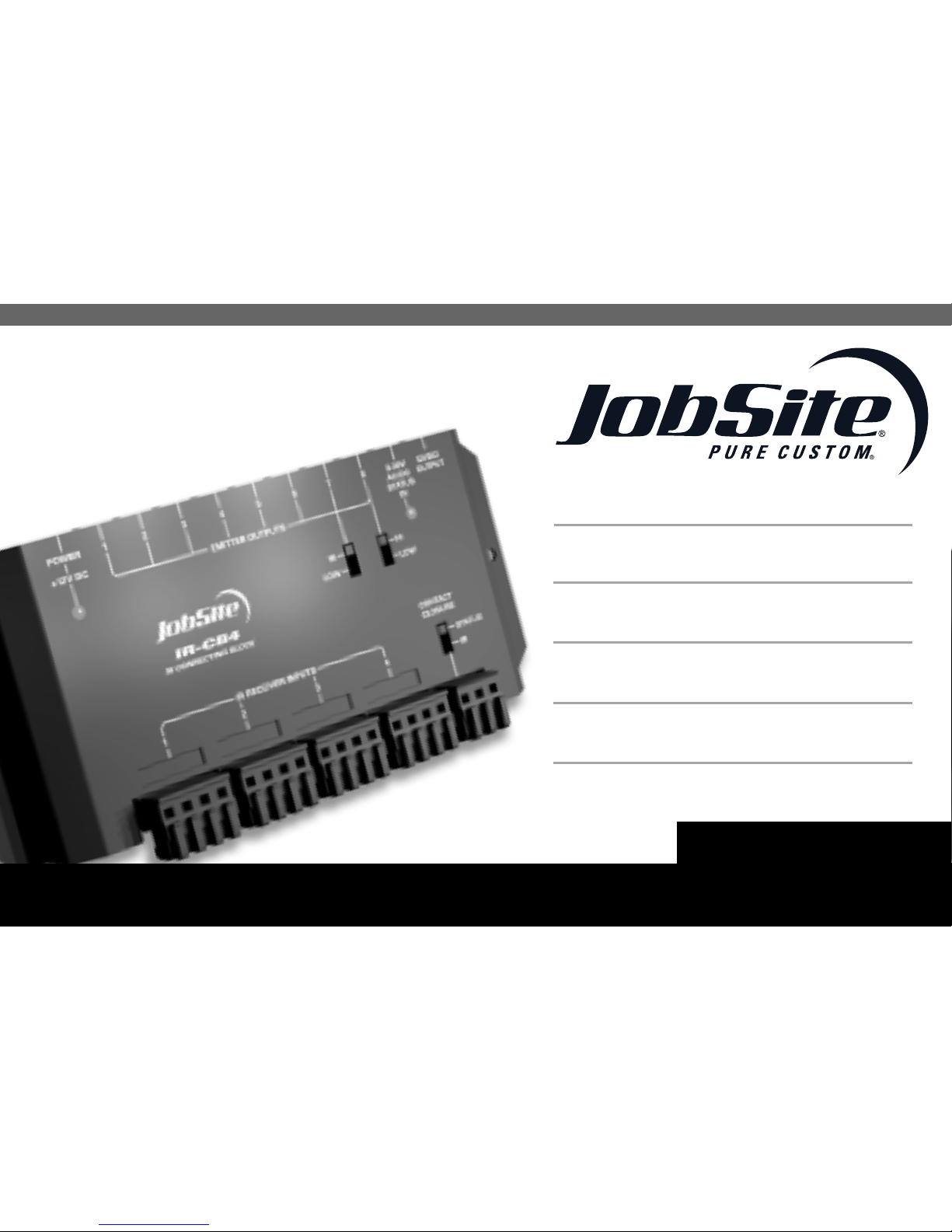
FOUR ZONE IR CONNECTING BLOCK
IR-CB4
For Routing Infrared
Commands from
Four IR Receivers
to Eight Sources
INSTALLATION & USER GUIDE

IR-CB4
FOUR ZONE IR CONNECTING BLOCK
TABLE OF CONTENTS
Features............................................................................................................................1
Product Overview...........................................................................................................2
Package Contents ..........................................................................................................4
Preparing for Installation..............................................................................................4
Installation.......................................................................................................................4
Troubleshooting ..............................................................................................................7
Specifications.................................................................................................................9
Warranty.........................................................................................................................10

1
FEATURES
nProvides four IR receiver inputs and eight IR emitter outputs
nTwo selectable high/low emitter outputs for use with IR-E1HO high output emitter or single and
dual emitters
nLED power indicator
n3.5mm 12V DC output jack triggered by sensing status or discrete IR commands
nContact closure triggered by sensing status or discrete IR commands
n12V DC status input jack and LED indicator
Installation friendly design:
nSnap and Lock Connector secures wire in place without the use of a screwdriver
n3.5mm emitter output jacks
nIncludes in-line UL listed regulated power supply
nWings allow for either vertical of horizontal mounting
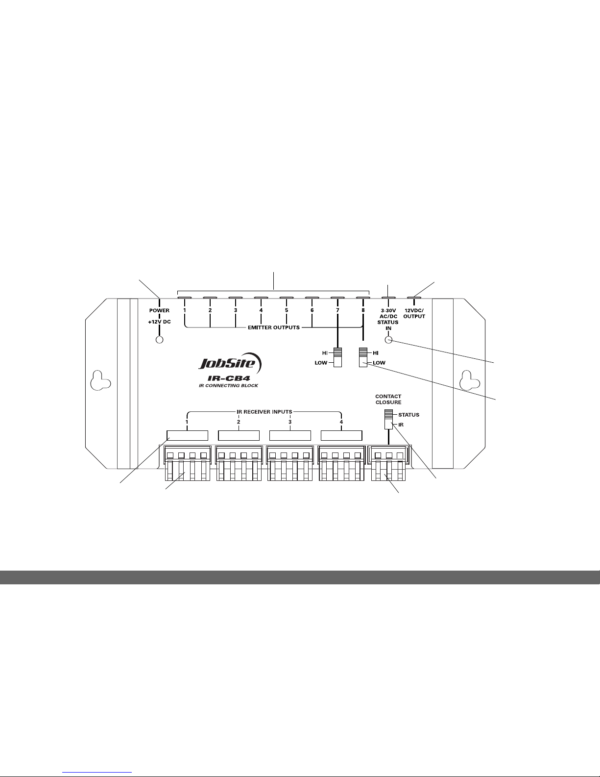
PRODUCT OVERVIEW
2
Figure 1
13
8
4
2
7
5
6
9
10

3
1. 12V DC Jack – Provides 12Volt DC power to
IR-CB4 via a regulated power supply.
2. IR emitter outputs – 3.5mm jacks provide output for
either single or dual low-level emitters.
3. 3-30V AC/DC Status – 3.5mm jack provides system
status to receivers/keypads via a 12Volt power
supply attached to a switched outlet on the system
receiver or a 12Volt trigger output.
4. 12V DC/200mA Output – When 12V DC voltage is
detected at the status jack or a discrete IR
command is issued 12V DC/200mA is output.
5. Status/IR Confirmation LED – This LED performs
two functions: (1) it provides a visible indication of
system status via a green LED and (2) confirms the
reception of IR data via a blinking blue LED.
6. Emitter Hi/Low switch – Setting these switches to
the appropriate position allows you to connect
either a high output flooding emitter (IR-E1HO) or
low output IR emitters. (IR-E1, IR-E2).
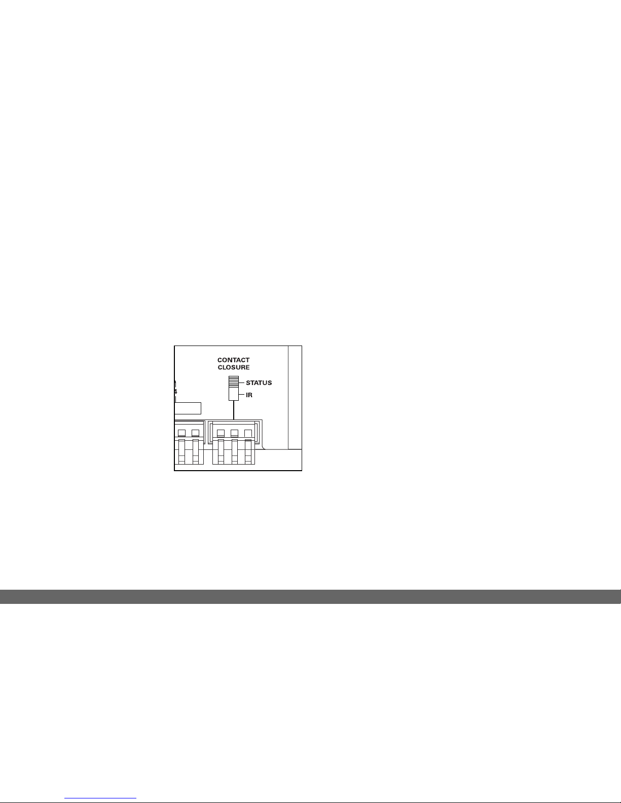
7. Contact Closure Switch – Two position switch that
determines if the contact closure is activated by
either (a) the presence of status or (b) discrete
IR commands.
8. Contact Closure Plug – Three position quick
connect plug for connecting either a NO (normally
open) or NC (normally closed) contact closure
device to the IR-CB4.
9. Receiver Input – Four position quick connect plug
for connecting IR receiver to the IR-CB4.
10. Receiver Input Labels – Recessed
label slot for installation of preprinted room
identification labels.

4
PACKAGE CONTENTS
nIR-CB4 x 1
nSnap and Lock Connectors x 5
nIn-line power supply x 1
nSelf-adhesive rubber feet x 4
PREPARING FOR INSTALLATION
The IR Receiver cables, Emitter cables and the 12V
DC power supply cable must all reach the proposed
location of the IR-CB4 connecting block. Mark the
cables with Wire labels, describing where the cables
originate from, rather than where they will terminate.
Locate a local un-switched AC outlet to be used to
power the IR-CB4 power supply.
Tools Required
n1/8" Slotted screwdriver
nWire stripper
nWire labels
INSTALLATION
1. Select an appropriate location for the IR-CB4.
2. Run all the necessary wiring to the IR-CB4. Label
the wires for future reference.
3. Plug the supplied 12V DC power supply into the un-
switched AC outlet.
4. Plug the 12V DC power supply connector into the
IR-CB4 socket marked POWER.
5. After verifying that the AC outlet works, unplug the
power supply connector.
6. Strip 1/4" of insulation from the end of each
CAT5 wire.
7. Locate the Snap and Lock Connectors and
remove them if they are plugged in.
8. Use a small flathead screwdriver or your thumb to
raise the locking tabs, exposing the holes on the
connectors.
9. Insert each wire into the appropriate hole and
snap down the locking tabs.
10. Insert the smooth side of the connector plug into
the smooth side of the IR-CB4 socket.
11. Connect the emitters to the emitter outputs.
12. Plug the 12V DC power supply connector into the
IR-CB4 socket marked POWER.
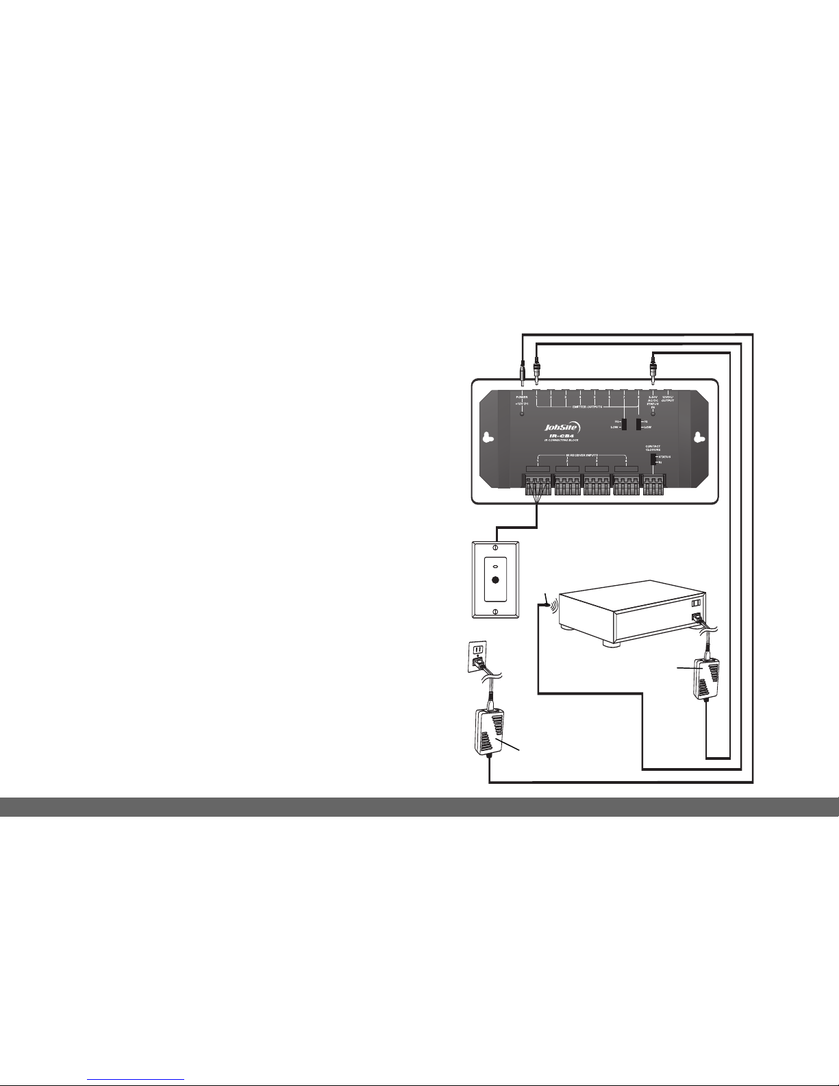
See installation diagram.
5
IR-CB4
Stereo Receiver
12V DC Power Supply
(Not Supplied) plugged into
the Switched Outlet
12V DC Power Supply
Plugged into an Unswitched
ACOutlet Powers the System
IR-WMR
JobSite
IR-E1
Emitter
INSTALLATION DIAGRAM
6
POWER STATUS
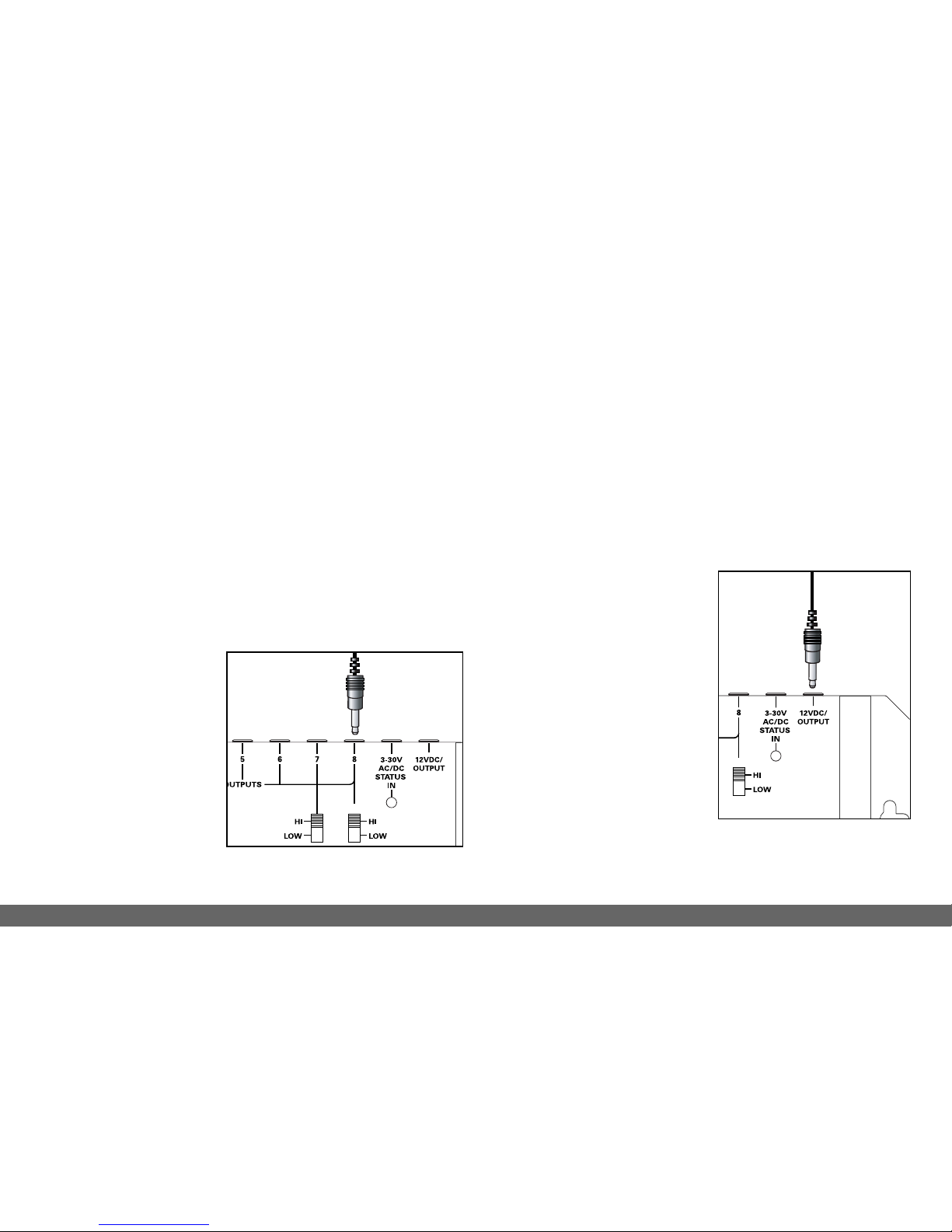
You can send a Power Status signal to all JobSite
IR Receivers by connecting a 12V DC power supply
from the switched AC power outlet of the
preamp/receiver to the status input jack of your
IR-CB4. Any 12V DC power supply with a minimum of
100mA current capacity can be used. See figure 2.
Hi / Low Emitter Output Switches
Emitter Output positions 7 and 8 have Hi / Low output
options. Set these switches to the appropriate
position depending on
what JobSite Emitter
you intend to use. If
you are using an IR-E1
or IR- E2 Emitter, set
the switch in the LOW
position. If you are
using a JobSite
IR-E1HO Emitter, set the switch in the HI position.
Note: Using an IR-E1 or IR-E2 Emitter with the Emitter
Output Switch set to the HI position, can damage the
Emitter. See Figure 3.
12-Volt Trigger Output
The JobSite IR-CB4 provides a 12V DC output that
can be triggered one of two ways:
1. The presence of status
voltage on the 12V DC
status input jack.
2. Discrete infrared On and
Off commands.
This output can be used to
trigger any device that
requires 12V DC to be
activated. See Figure 4.
Figure 2
Figure 3
7
Contact Closure
The JobSite IR-CB4 provides a contact closure that
can be triggered one of two ways:
1. The presence of status voltage on the 3-30V AC/DC
status input jack.
2. Discrete infrared on and off commands.
Set the contact closure
dip switch, located above
the screwless connector,
to the appropriate position
for triggering.
See Figure 4.
The discrete on and off
commands are available for
download at:
www.Jobsitesystems.com/technicalsupport/
TROUBLESHOOTING
Bad Connections or Wiring
If the connections or wiring are wrong, loose,
shorted or open the system will not operate properly.
The symptoms could include: Power LED flickers or
is off, IR Test LED is continuously flickering or on
without any remote control use, intermittent
operation or no operation.
Solution:
1. Test your power supply connections.
2. Test your receiver connections.
3. Test your emitter connections.
4. Test your cable for shorts and opens.
Figure 4 Contact closure.

8
IR Saturation
Sometimes the emitter output can saturate the IR
receiving window of a component. When this
occurs, the IR command will not be executed. This
can occur on an intermittent basis when there is a
Plasma TV in the system.
Solution:
1. Remove the IR Blocking Cover if you are using one.
2. Turn on the Plasma TV, because this may be
contributing to the problem.
3. Relocate the IR Emitter approximately 1/2" away
from the IR Receiving window.
4. Some experimentation will be required to
determine the best location for emitter.
5. Test system. Do not use an IR Blocking Cover if a
component is sensitive to IR saturation.
Optical or Electromagnetic
Interference
Direct sunlight, reflections, neon signs and other
sources of infrared light or television sets, light
dimming controls and other sources of
electromagnetic fields can induce noise and
interference into your IR repeater system. Symptoms
can include: flashback LEDs continuously flickering
or on without any remote control use, poor range,
intermittent operation or no operation.
Solution:
1. Move the receiver or the receiver cable away from
the EMI source or move the source of the EMI
away from the Receiver or the cable.
2. Connect the receiver’sGND terminal to true earth
ground (if this isn’tfeasible use the main system
unit’s GND terminal).
Altri manuali per IR-CB4
1
Indice
Altri manuali Jobsite Ricevitore

Jobsite
Jobsite IR-WMR MKII Manuale utente

Jobsite
Jobsite M-64 Manuale operativo

Jobsite
Jobsite IR-CB4 Manuale utente

Jobsite
Jobsite IR-FMR Manuale utente

Jobsite
Jobsite M-64 Manuale utente

Jobsite
Jobsite IR-FMR MKII Manuale utente

Jobsite
Jobsite IR-CB2 Manuale operativo

Jobsite
Jobsite IR-CB1 Manuale operativo

Jobsite
Jobsite IR-CB1 Manuale utente

Jobsite
Jobsite IR-SMR MKII Manuale utente


