
JVC CH-X400 Manuale utente
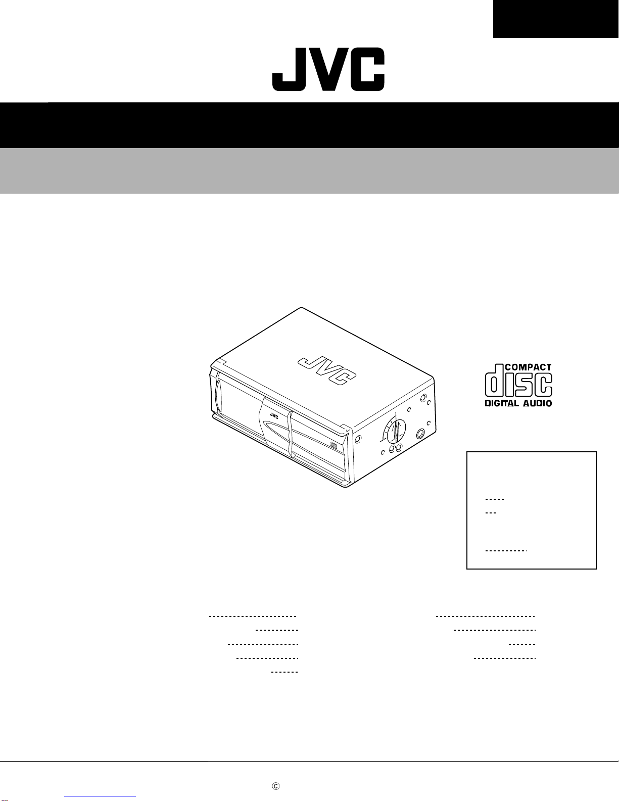
SERVICE MANUAL
COMPACT DISC AUTOMATIC CHANGER
No.49585
Dec. 2000
COPYRIGHT 2000 VICTOR COMPANY OF JAPAN, LTD.
CH-X400 / CH-X450
CH-X400 / CH-X450
Contents
Safety precaution
Important for laser products
Location of main parts
Removal of main parts
JC 12 Forced eject procedures
1-2
1-3
1-4
1-5
1-19
Troubleshooting
Wiring connections
Pickup replacement procedure
Description of major ICs
1-20
1-26
1-27
1-29
This service manual is printed on 100% recycled paper.
Area Suffix
J Northern America
E Continental Europe
CH-X400
U Other areas
CH-X450
CH-X400/CH-X450
1-2
!Burrs formed during molding may be left over on some parts of the chassis. Therefore,
pay attention to such burrs in the case of preforming repair of this system.
Safety precaution
!Please use enough caution not to see the beam directly or touch it in case of an
adjustment or operation check.
CH-X400/CH-X450
1-3
Important for laser products
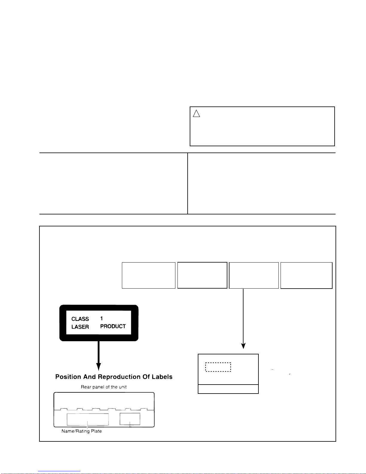
1.CLASS 1 LASER PRODUCT
2.DANGER : Invisible laser radiation when open and inter
lock failed or defeated. Avoid direct exposure to beam.
3.CAUTION : There are no serviceable parts inside the
Laser Unit. Do not disassemble the Laser Unit. Replace
the complete Laser Unit if it malfunctions.
4.CAUTION : The compact disc player uses invisible
laserradiation and is equipped with safety switches
whichprevent emission of radiation when the drawer is
open and the safety interlocks have failed or are de
feated. It is dangerous to defeat the safety switches.
5.CAUTION : If safety switches malfunction, the laser is able
to function.
6.CAUTION : Use of controls, adjustments or performance of
procedures other than those specified herein may result in
hazardous radiation exposure.
VARNING : Osynlig laserstrålning är denna del är öppnad
och spårren är urkopplad. Betrakta ej strålen.
VARO : Avattaessa ja suojalukitus ohitettaessa olet
alttiina näkymättömälle lasersäteilylle.Älä katso
säteeseen.
ADVARSEL : Usynlig laserstråling ved åbning , når
sikkerhedsafbrydere er ude af funktion. Undgå
udsættelse for stråling.
ADVARSEL : Usynlig laserstråling ved åpning,når
sikkerhetsbryteren er avslott. unngå utsettelse
for stråling.
REPRODUCTION AND POSITION OF LABELS
WARNING LABEL
DANGER : Invisibie laser radiation
when open and interlock or
defeated.
AVOID DIRECT EXPOSURE TO
BEAM (e)
VARNING : Osynlig laserstrålning är
denna del är öppnad och spårren är
urkopplad. Betrakta ej strålen. (s)
VARO : Avattaessa ja suojalukitus
ohitettaessa olet alttiina
näkymättömälle lasersäteilylle.Älä
katso säteeseen. (d)
ADVARSEL :Usynlig laserstråling
ved åbning , når
sikkerhedsafbrydere er ude af
funktion. Undgå udsættelse for
stråling. (f)
!
CAUTION
Please use enough caution not to
see the beam directly or touch it
in case of an adjustment or operation
check.
Caution.
This production
contains laser
component
of higher laser class
than Class 1.
Top panel of the unit
Gerateoberseite
Panneau superieur de l"appereil
CH-X400/CH-X450
1-4
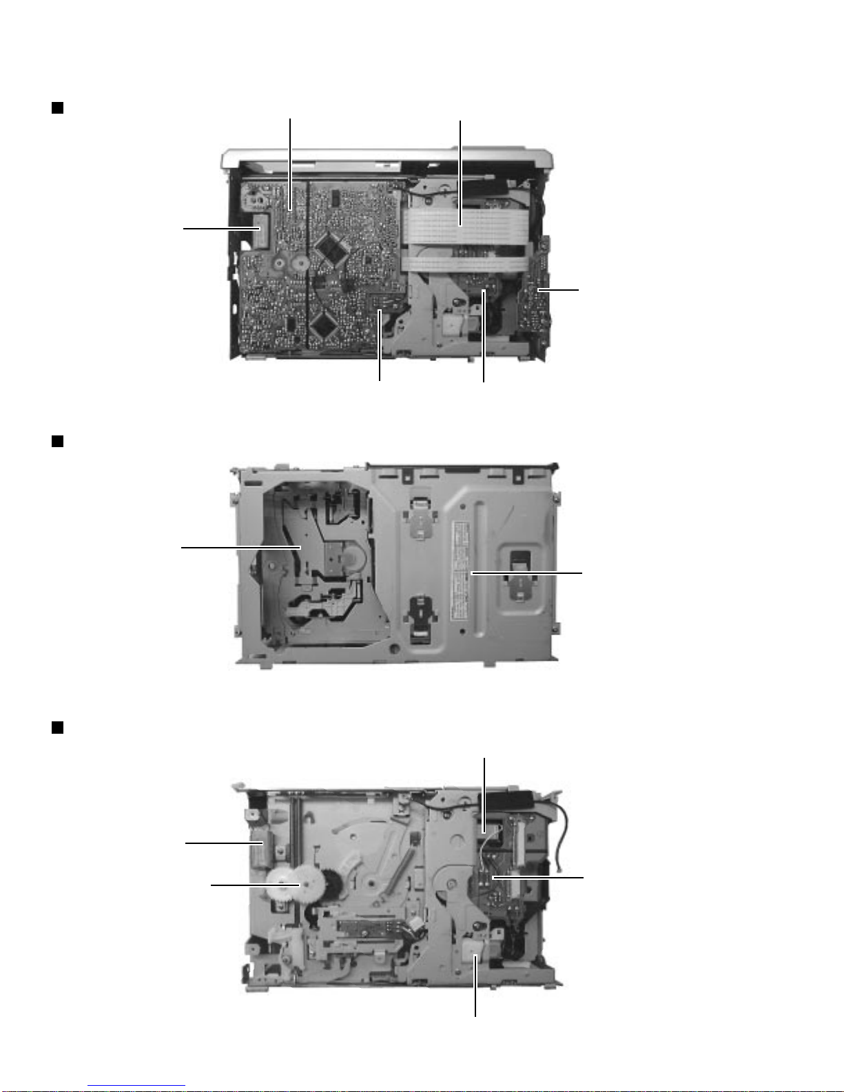
Location of main parts
Bottom view
Top side view
Remove the main board view
Main board ass'y Mechanism ass'y wire
Jack board ass'y
Mechanism board ass'ySensor board ass'y
Positioning
motor ass'y
Mechanism &
lifter unit
Positioning
motor ass'y
Feed motor
Spindle motor
Tray motorSensor board ass'y
Third gear
Magazine house
section

CH-X400/CH-X450
1-5
1. Remove the screw (1-a) to unlock the mounting direction
knob located on the side of the main unit.
2.Turn the mounting direction knob in the direction of the arrow
using a coin, etc. to remove it. (The knob can be removed
only when it is set to this position.)
3. Remove the four top cover fixing screws (1) at the triangle
(A) marks on the side of the main unit. (Perform the same
operation on both sides.)
4.Turn the unit upside down so the bottom surface is facing
upward.
5. Lift the rear edge of the bottom cover slightly and lift the side
by grasping the DIN jack section on the side panel, then
turn it toward the front (raise upward) to remove the bottom
cover.
6. Unhook the four catches located on both sides of the front
panel, and turn the front panel toward the top cover (lower
down) to remove the front panel.
Remove 1-a and
turn in the direction
of the arrow.
Fig. 1
Fig. 2
Fig. 3 Fig. 4
Exterior section
Removing the bottom cover and front panel
assembly 11
111-a
11
1
11-a
Remove 1-a and
turn in the
direction of the
arrow
Unhook catches
Unhook catches
The front panel can be
separated by raising the
cover.
Slightly lift the
jack section to
remove.
Disassembling procedures
Perform operations according to the items to be disassembled.
Replacement of the Pickup
1. After removing the exterior (top and bottom)...
2. Proceed to the "Pickup Replacement" section.
3.When applying grease, refer to the Exploded View.
Use new grease.
Mechanism section
1. Remove the exterior (required section only).
2.The mechanism section is designed so that each unit can be
removed separately.
3.When reassembling, refer to the assembling precautions.
(Use new grease when applying grease.)
Removal of main parts
CH-X400/CH-X450
1-6
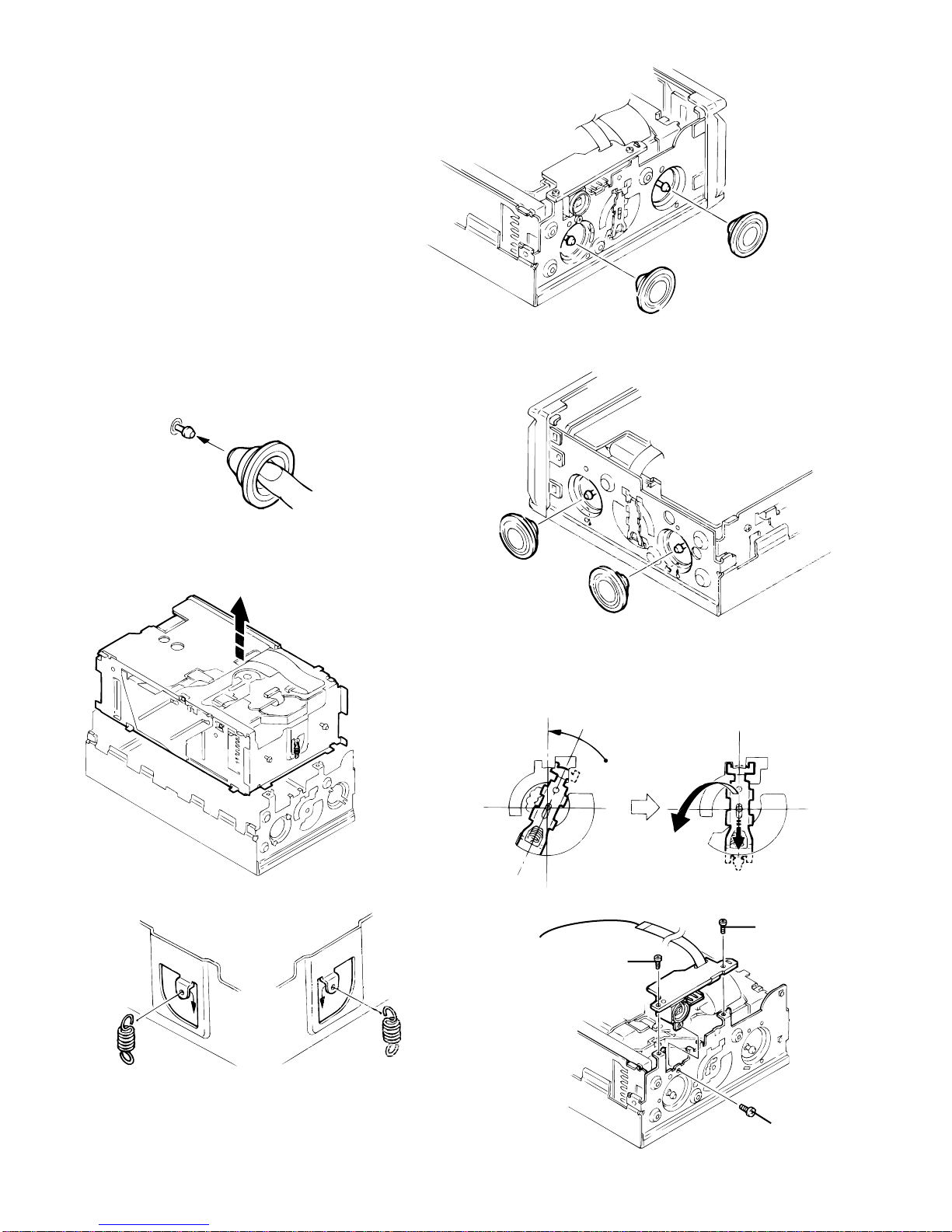
Removing the top cover
1. Pull out the dampers, being careful not to damage.
When reattaching a damper, insert your finger to push out the
center of the damper to mount it on the damper shaft, as
shown in Fig.6-1.
2.Turn the damper spring bracket toward the top at a right angle
as shown in Fig.7, then push down the lower side of the
damper spring bracket to lift it off.
3. Remove the three fixing screws (3) and (4) on the DIN jack
PCB assembly.
4. Lift the changer unit upward.
5. Remove the damper springs from the mechanism chassis if
required. To reassemble, refer to the diagram below.
Fig. 5
Fig 6
Fig. 6-1
Fig. 7
Fig. 8
Fig. 8-1
Fig. 9
Apply alcohol to the shaft then
immediately attach the damper. (After
attaching, check that the shaft is
correctly inserted.)
Push out with your
finger before
attaching
Turn to the top position (at a right angle),
then push down to lift off.
Lift the changer unit upward
How to attach the damper springs
Silver
(mechanism side) Red
(magazine side)
Mechanism
Chassis
Remove the flexible ribbon
wire if required
4
4
3
CH-X400/CH-X450
1-7
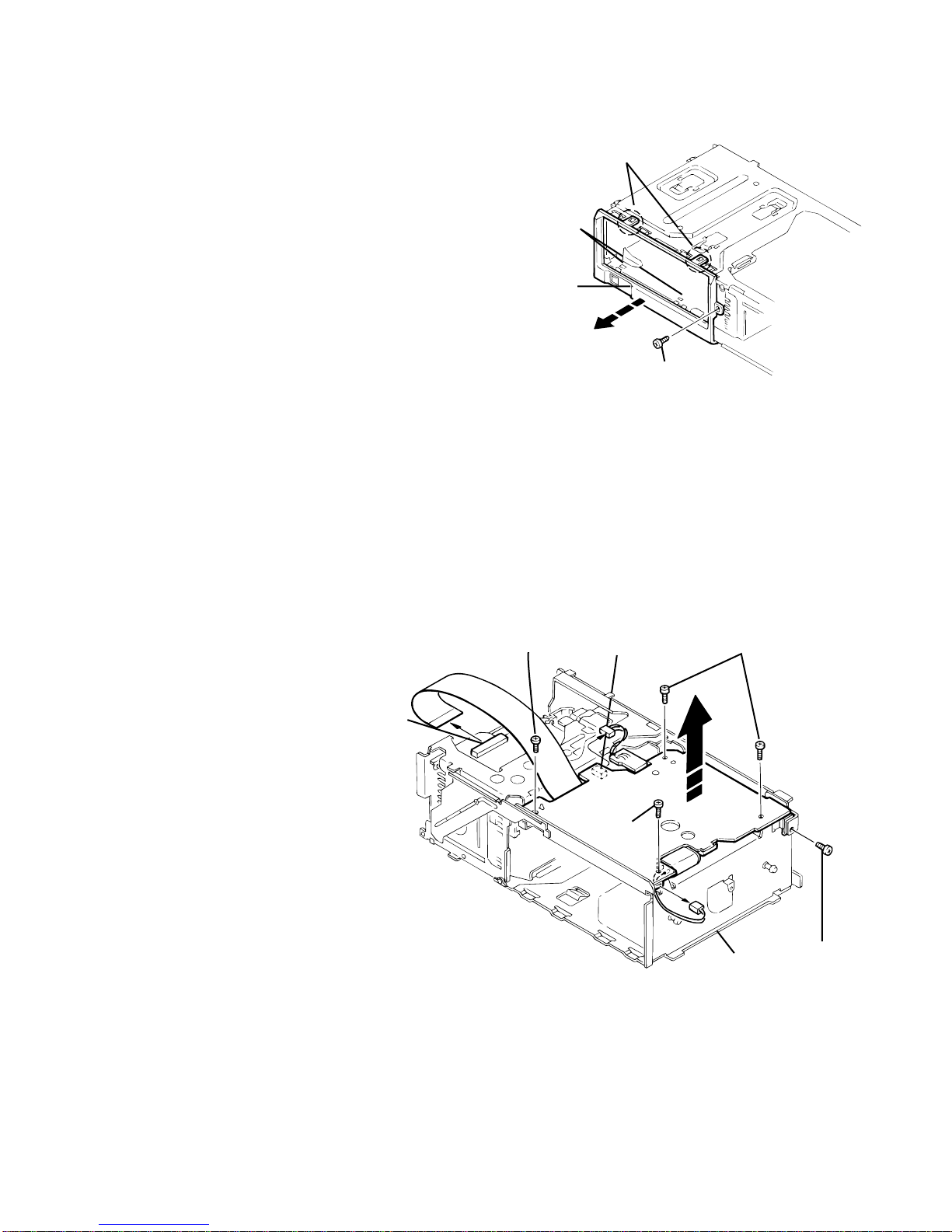
Removing the fittings
Removing the main PCB assembly
1. Remove the fixing screw (5).
2. Unhook the two catches (a) on the top edge of the fitting,
then unhook the catches (b) at the left/right bottom edges.
1. Remove the power IC fixing screw (6).
2. Remove the four screws (7) securing the main PCB
assembly.
3. Disconnect position motor wire connector CN504 from the
main PCB assembly.
4. Disconnect sensor PCB assembly wire connector CN601
from the main PCB assembly.
5. Remove the flexible ribbon wire from CN502 on the traverse
mechanism PCB assembly.
When reinstalling the PC boards, refer to the reassembling
procedures for protecting switches, etc.
Catches (a)
Catches (b)
Fitting
5
7 CN601 7
7
Fig. 10
Fig. 11
6
CN504
CN502
CH-X400/CH-X450
1-8
Fig. 12
Fig. 13
Fig. 14
Sensor
assembly
1
1
a
Rear
Magazine lock spring
Poly-washer (b)
c
Positioning
motor assembly
2
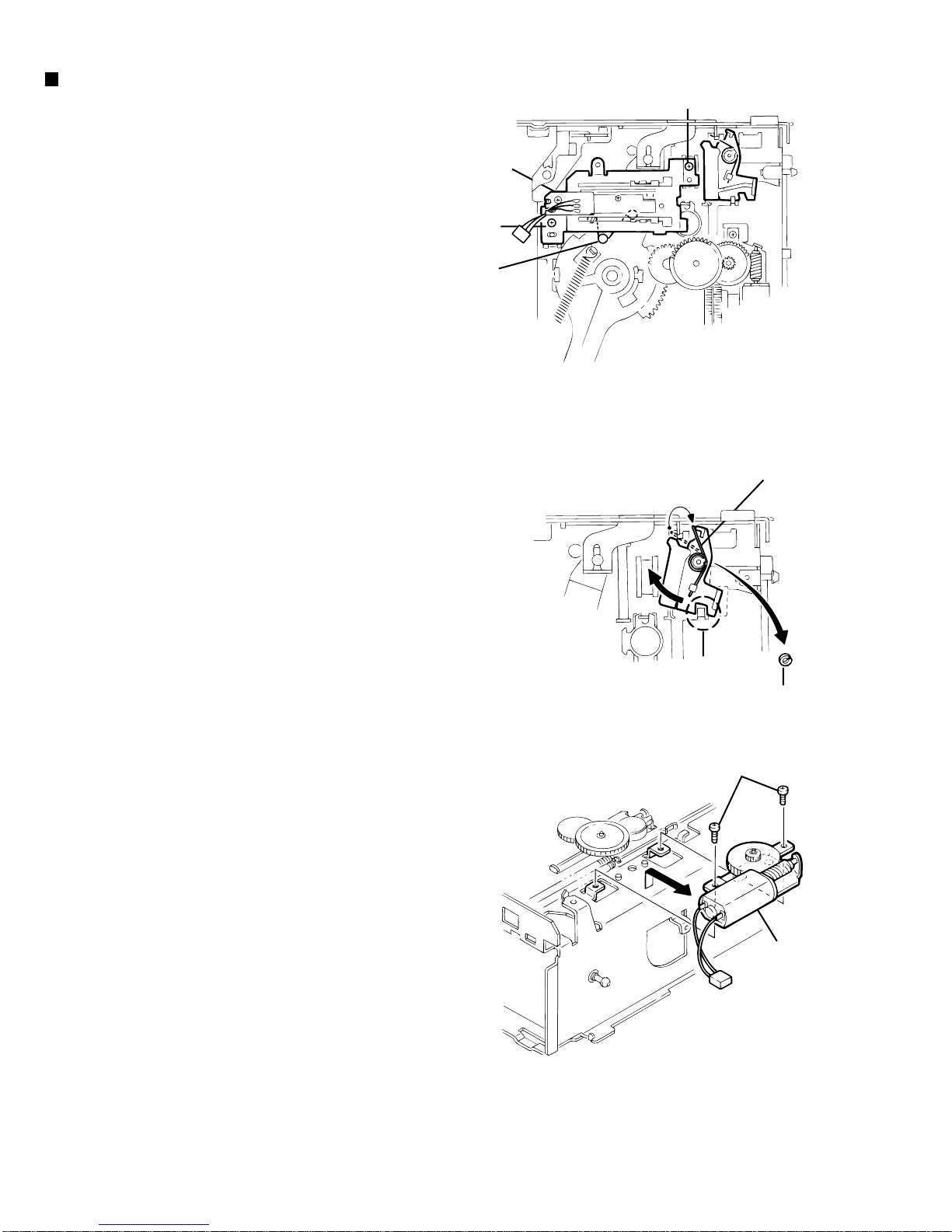
Changer mechanism section
Sensor assembly unit
1. Remove the two screws (1) securing the sensor assembly
unit.
2. Unhook the springs on the back of the sensor assembly unit
from the holes on the chassis.
Magazine lock arm
1. Remove the magazine lock spring from the front side of the
chassis.
2. Remove the poly-washer (b) securing the magazine lock arm.
3.Turn the magazine lock arm in the direction of the arrow until
the notch is at the "C" position to remove it from the chassis.
Positioning motor assembly
1. Remove the two screws (2) securing the positioning motor.
2. Slightly lift the positioning motor assembly to remove it from
the two burrs on the chassis.
CH-X400/CH-X450
1-9
Can be removed at the stud position
(at the widest hole) Remove
Shift
Third gear
Fig. 15
Fig. 16
Fig. 17
Fig. 18
Remove the E-washer
Third gear
Slide and remove the rod inside
Slide
Rod
Top Plate
Remove
After lifting
3
3
3
3
3
e
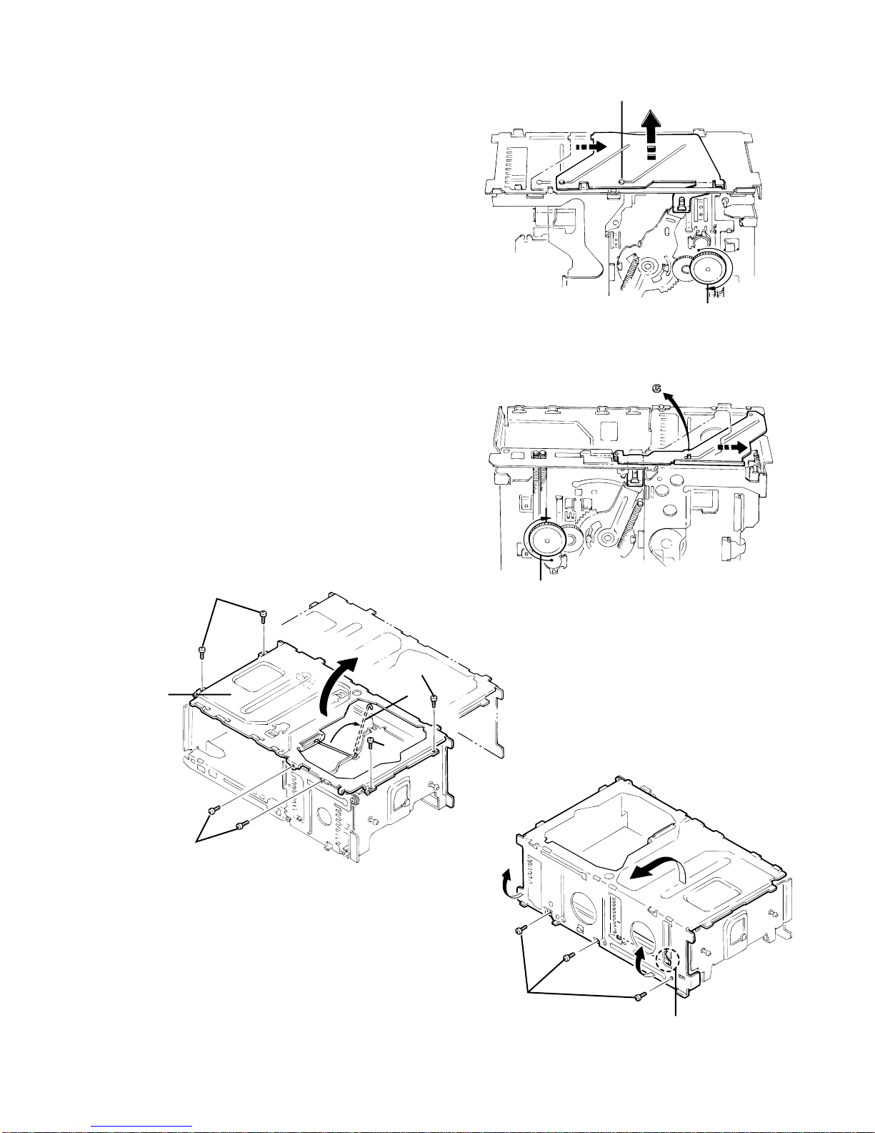
Rear slider
1. Position the unit with the front section facing down. Rotate
the third gear located on the back of the main unit in the
direction of the arrow (clockwise).
2. Shift the rear slider in the direction of the arrow and remove it
at the rear slider mounting position (at the widest hole).
Front slider
1. Position the unit with the rear section facing down. Rotate the
third gear located on the bottom of the unit in the direction of
the arrow (clockwise) until the front slider is shifted to the
outermost position.
2. Remove the E-washer securing the front slider to remove the
front slider from the chassis.
Top plate
1. Remove the nine screws (3) securing the top plate.
2. Disconnect the section (e) attached to the rear of the unit,
then lift the top plate slightly.
3. Slide the top plate toward the rear of the unit to remove the
upper rod from the top plate.
CH-X400/CH-X450
1-10
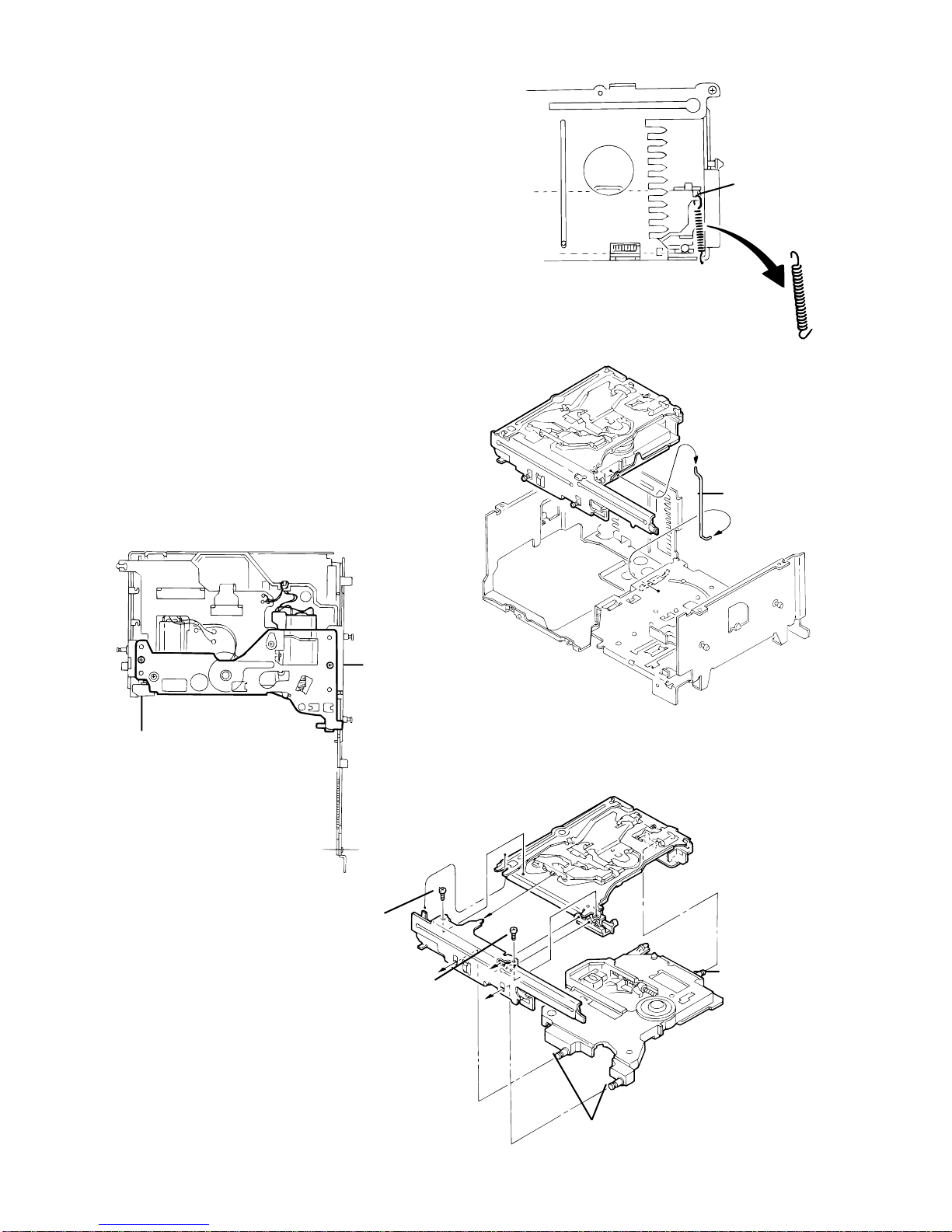
Lifter unit
1. Unhook the elevator spring located on the front side of the
unit.
(Be sure to first unhook the spring from the lifter side as
shown in the upper part of the diagram.)
2. Lift the lifter unit upward, then remove the lower rod to
remove the lifter unit from the chassis.
Lifter bracket
1. Remove the two lifter bracket fixing screws (4) located on the
back of the lifter unit.
2. Remove the lower rod.
Side bracket and traverse mechanism
1. Remove the two side bracket unit fixing screws (5) to
disconnect the side bracket unit from the lifter unit.
2. Remove the three shafts on the traverse mechanism
assembly from the lifter unit.
For reassembling, refer to the reassembling
procedures.
Fig. 19
Fig. 20
Fig. 21
Fig. 22
Unhook this
part first
Proper
orientation
Lift up the lifter unit
Lower rod
Remove from the
lifter unit
Remove from the
lifter unit
5
5
4
4
Altri manuali per CH-X400
3
Questo manuale è adatto per i seguenti modelli
1
Indice
Altri manuali JVC Ricevitore per auto

JVC
JVC KD-SX875 Manuale utente

JVC
JVC KW-R700BT Manuale utente

JVC
JVC KW-ADV794 Manuale utente

JVC
JVC KD-LH7R Manuale utente

JVC
JVC KS-FX772R Manuale utente

JVC
JVC KD-S747 Guida per l'amministratore

JVC
JVC KD-LH811 Guida

JVC
JVC KD-LH3150J Guida per l'amministratore

JVC
JVC KV-MRD900A Guida

JVC
JVC KW-XR416 Guida

JVC
JVC KD-G343 Manuale utente

JVC
JVC KW-ADV65BT Manuale utente

JVC
JVC GET0647-004A Guida

JVC
JVC KD-APD38 Manuale utente

JVC
JVC KS-FX202 Manuale utente

JVC
JVC KW-XR411 Manuale utente

JVC
JVC KD-G200 Manuale utente

JVC
JVC KD-AR270 - Radio / CD Manuale utente

JVC
JVC KD-HDR44 Manuale utente

JVC
JVC KD-SX740J Manuale utente


