K40 Defuser EX Manuale utente

Installation
Installation
Instructions
Instructions
& Recommended
Procedures
LASER DEFUSER EX
(FRONT LICENSE PLATE MOUNT WITH FRAME)
1. Remove the mounting bolts and any existing frame or cover from the license plate. Remove license plate.
2. Position the Laser Defuser EX around the existing front license plate and mount it against the factory license
plate bracket. Use the existing mounting bolts or K40 supplied nylon bolts to secure the Laser Defuser EX
frame and license plate to the bracket.
The Defuser EX system is ideal for small to mid-size vehicles, and comes packaged in an ordinary looking
license plate frame. It may be installed with or without the license plate frame as needed.
The Defuser EX2 system is recommended for larger size vehicles, or when a front license plate mount
is not used on the vehicle. The system includes two separate Defuser modules with no license plate frames.
On vehicles that have only one set of bracket mounting holes, it is recommended that the Laser
Defuser EX and the license plate be bolted together to eliminate any vibration.
DIAGRAM A3
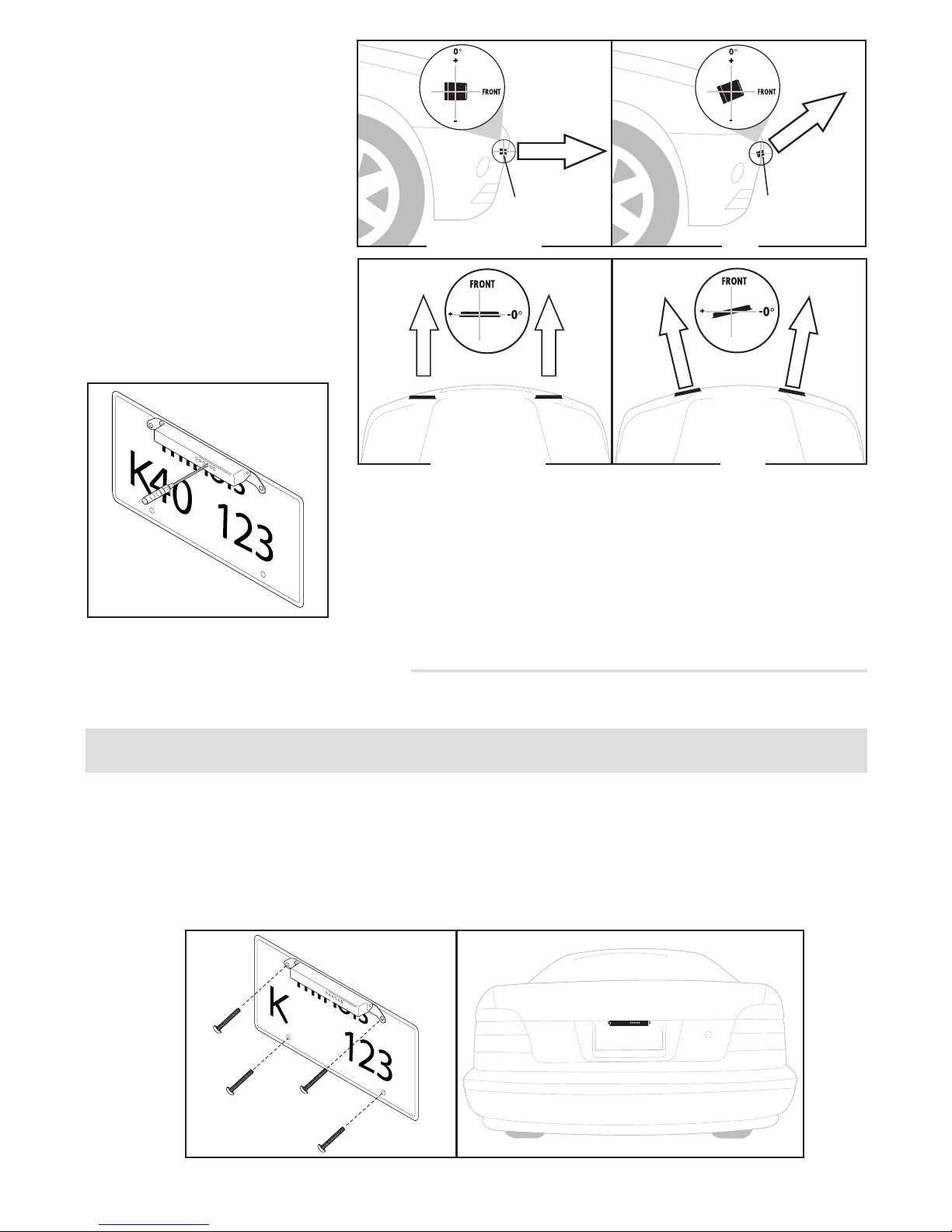
3. For proper performance, the Defuser EX must be mounted completely level. A unit which is positioned up,
down, or to the side by as little as 1° can reduce jamming effectiveness by as much as several hundred feet
(see diagram A1).
To assure the Defuser EX is properly leveled, insert the rod on the K40 supplied level into the leveling assem-
bly hole located on the top of the Defuser EX frame (see diagram A2). Be sure that the vehicle is on a level
surface before checking installation.
NOTE:
DIAGRAM A1
DIAGRAM A2
Use the K40 supplied nylon nuts
and bolts to correct either up or
down as needed (see diagram A3).
4. Route the black cable into the engine
compartment either through the grill
or under the bumper. Connect wires
per the separate enclosed block
diagram sheet.
On some vehicles, it may be necessary to adjust or reposition the factory license plate bracket to
achieve the desired level installation.
NOTE:
LASER
DEFUSER
FACTORY
MOUNTING
LOCATION
MOUNTING NUTS
JAMMING BEAM
LASER
DEFUSER EX
Enlarged
View Enlarged
View Enlarged
View
JAMMING BEAM
LASER
DEFUSER EX
LASER
DEFUSER EX
JAMMING BEAM
CORRECT NO NO

LASER DEFUSER EX & EX2
(FRONT CUSTOM MOUNT WITHOUT FRAME)
DIAGRAM B1
Diagram B3
BRACKET
TAPE
1/4”SCREW
LASER DEFUSER
BRACKET
TAPE
LASER DEFUSER
1/4”SCREW
WITHOUT
HORIZONTAL
TABS
WITH
HORIZONTAL
TABS
3. If utilizing the supplied universal mounting bracket(s), determine which holes will be used to mount the
Defuser module(s) to the vehicle. Remove the unused mounting tabs on the bracket(s) as needed.
4. Apply the supplied double stick tape directly to the Defuser module(s) and attach the module(s) to the
universal mounting bracket(s) with the included 1/4” screws ( diagram B3).
1/4”
SCREW 1/4”
SCREW
CENTERED & UN-
OBSTRUCTED DO NOT PUT BEHIND GRILL
DO NOT OBSTRUCT VIEW DO NOT MOUNT OFF CENTER
2. For the dual Defuser EX2, choose separate mounting locations on either side of the license plate area and/or
center of the vehicle. For proper performance, the EX2 modules should be spaced 18" apart from one
another, and cannot be obstructed in any way or recessed into the vehicle (see diagram B2).
DO NOT PUT BEHIND GRILL
DO NOT OBSTRUCT VIEW
DIAGRAM B2
1. For the single Defuser EX, choose a mounting location near the center of the vehicle that has a clear, unob-
structed view of the road . Units which are mounted off center, are recessed into the vehicle, or which are
obstructed in any way will not perform properly (see diagram B1).
If using an EX system, first separate the module from the license plate frame by removing the
two screws on the backside of the frame.
NOTE:
CORRECTLY SPACED
& UNOBSTRUCTED
DO NOT SPACE MODULES
MORE THAN 18” APART
5. Install the Defuser module(s) to
the desired mounting surface
using the included 3/4” screws
or nylon mounting nuts and
bolts.
6. For proper performance, the
Defuser EX and EX2 must be
mounted completely level. A
unit which is positioned up,
down, or to the side by as little
as 1° can reduce jamming effec-
tiveness by as much as several
hundred feet (see diagram B4).
Be sure that the vehicle is on a
level surface before checking
installation.
JAMMING BEAM
Enlarged
View
JAMMING BEAM
LASER DEFUSER
Enlarged
View
NO
CORRECT
LASER DEFUSER
DIAGRAM B4
Enlarged
View
NO
JAMMING BEAM
LASER DEFUSER(S)
Enlarged
View
CORRECT
JAMMING BEAM
LASER DEFUSER EX & EX2
(REAR LICENSE PLATE MOUNT WITHOUT FRAME)
1. Remove the mounting bolts and any existing frame or cover from the rear license plate. Remove license plate.
2. Remove the three unused horizontal mounting tabs from the top of the supplied universal mounting bracket.
3. Apply the supplied double stick tape directly to the Defuser module and attach it to the mounting bracket with
the included 1/4” screws. Position the Defuser module against the license plate and mount it to the factory
license plate bracket using the existing mounting bolts or K40 supplied nylon bolts (see diagram C1)
To assure the Defuser module(s) is/are properly leveled, insert the rod
on the K40 supplied level into the leveling assembly hole located near
the middle of the Defuser module(s)(see diagram B5).
7. Route the black cable(s) into the engine compartment, either through
the grill or under the bumper. Connect the Defuser EX or EX2 wires
per the separate enclosed block diagram sheet.
DIAGRAM B5
If using an EX system, first separate the module from the license plate frame by removing the
two screws on the backside of the frame.
NOTE:
DIAGRAM C1
40
JAMMING BEAM
JAMMING BEAM
LASER DEFUSER(S)

LASER DEFUSER
FACTORY
MOUNTING
LOCATION
LASER DEFUSER
FACTORY
MOUNTING
LOCATION
LASER DEFUSER
FACTORY
MOUNTING
LOCATION
DIAGRAM C2
4. For proper performance, the Defuser module must be mounted completely level. A module which is posi-
tioned up, down, or to the side by as little as 1° can reduce jamming effectiveness by as much as several
hundred feet (see diagram C2). To assure the Defuser module is properly leveled, insert the rod on the K40
supplied level into the leveling assembly hole located near the middle of the Defuser module (see diagram C3).
Be sure that the vehicle is on a level surface before checking installation.
5. Route the black cable into the trunk. Connect wires per the separate enclosed block diagram sheet.
44678 6/07
DIAGRAM C3
LASER DEFUSER EX
(REAR LICENSE PLATE MOUNT WITH FRAME)
1. Remove the mounting bolts and any existing frame or cover from the license plate. Remove license plate.
2. Position the Laser Defuser EX around the existing rear license plate and mount it against the factory license
plate bracket. Use the existing mounting bolts or K40 supplied nylon bolts to secure the Laser Defuser EX
frame and license plate to the bracket.
On vehicles that have only one set of bracket mounting holes, it is recommended that the Laser
Defuser EX and the license plate be bolted together to eliminate any vibration.
3. For proper performance, the Defuser EX must be mounted completely level. A unit which is positioned up,
down, or to the side by as little as 1° can reduce jamming effectiveness by as much as several hundred feet
(see diagram D1). To assure the Defuser EX is properly leveled, insert the rod on the K40 supplied level into
the leveling assembly hole located on the top of the Defuser EX frame (see diagram D2). Be sure that the
vehicle is on a level surface before checking installation.
4. Use the K40 supplied nylon nuts and bolts to correct either up or down as needed ).
5. Route the black cable into the trunk. Connect wires per the separate enclosed block diagram sheet.
NOTE:
LASER DEFUSER
FACTORY
MOUNTING
LOCATION
LASER DEFUSER
FACTORY
MOUNTING
LOCATION
LASER DEFUSER
FACTORY
MOUNTING
LOCATION
DIAGRAM D1 DIAGRAM D2
Questo manuale è adatto per i seguenti modelli
1
Indice
Altri manuali K40 Rilevatore radar


