Langham 20265 Manuale utente
9049 • 01/10/14
52”LANGHAM
CEILING FAN
Owner’s Manual
Models #20265, 20266
Turn of the CenturyTM
1
If a problem cannot be remedied or you are experiencing diculty in installation,
please contact the Service Department: 1-877-459-3267, 9 a.m.- 5 p.m. Central time.

TM
Turn of the Century
PACKAGE CONTENTS
2
HARDWARE CONTENTS
18
19
20
21
22 25
24
23
26
27
28
29
30
1. Canopy
2. Canopy Cover
3. Mounting Bracket
4. Motor Housing
5. Switch Housing
6. Switch Housing Cap
7. Light Kit
8. Glass Shade
9. Finial Cap
10. Finial
11. Downrod
12. Adapter Cover
13. Blade Arm (x 5)
14. Candelabra Bulb (x 3)
15. Blade (x 5)
16. Hardware Kit
17. Installation Instructions
18. Pull Chain Extension (x 2)
18. Motor Screw (x 10)
19. Mounting Bracket
Screw(x 4)
20. Blade Screw (x 15)
21. Closemount Screw (x 3)
22. Downrod Set Screw (x 2)
23. Star Washer (x 4)
24. Blade Washer (X 15)
25. Switch Housing Screw (x 3)
26. Plug Button
27. Wire Connector (x 3)
28. Downrod Clip
29. Downrod Pin
30. Blade Isolator
Unpack your fan and check the contents. You should
have the following items:
PACKAGE CONTENTS
HARDWARE CONTENTS
Note: Some extra hardware has been included. The quantity
listed above is the number required for installation.
17
18
6
5
4
3
2
1
10
11
7
8
9
13
16
15
14
12

TM
Turn of the Century
MOUNTING OPTIONS
3
Triple Mount Drawing
Closemount
Downrod Mount
Slope Ceiling Mount (Up to 23 degrees)
A. 18.90 in. B. 12.20 in. C. 2.40 in. D. 11.18 in. E. 5.08 in.
DIMENSION REFERENCE
E
D
C
B
A
Choose one of the following mounting options:
Closemount method is best suited for ceilings lower than 8 feet. It does not utilize the downrod.
Downrod Mount is best suited for ceilings 8 ft. or higher. For taller ceilings you may want to use a longer
downrod (not included).
Angled Ceiling Mount is best suited for angled or vaulted ceilings. A longer downrod is sometimes necessary to
ensure proper blade clearance from the ceiling. If using the angle mount, check to ensure the ceiling angle is not
steeper than 23°.

TM
Turn of the Century
WARNING
READ ALL SAFETY INFORMATION AND INSTALLATION INSTRUCTIONS BEFORE YOU BEGIN INSTALLING THE
FAN AND SAVE INSTRUCTIONS.
All set screws of the fan must be checked and retightened where necessary before installation.
To reduce the risk of personal injury, do not bend the blade brackets when installing the brackets, balancing
the blades or cleaning fan. Do not insert foreign objects in between rotating fan blades.
Before changing the fan direction, turn o the fan and wait for the fan blades to stop completely.
If a stationary appliance is not provided with a supply cord and a plug, or with other means for
disconnection from the main supply having a contact separation of at least 3 mm in all poles, that means for
disconnection must be incorporated in the xed wiring in accordance with the wiring rules.
NOTE: The safeguards provided by these safety instructions and by the separate installation instructions
are not meant to cover all possible conditions and situations that may occur. It must be understood that
common sense, caution and care are factors which can not be built into this product. These factors must be
supplied by the person(s) installing, caring for and operating the fan.
TO AVOID RISK OF ELECTRIC SHOCK, BE SURE TO SHUT OFF POWER AT THE MAIN FUSE OR CIRCUIT
BREAKER BOX BEFORE INSTALLING OR SERVICING THIS FIXTURE. TURNING OFF THE ELECTRICAL POWER
BY USING THE LIGHT SWITCH IS NOT SUFFICIENT TO PREVENT ELECTRICAL SHOCK.
TO REDUCE THE RISK OF INJURY, INSTALL THE FAN SO THAT THE BLADES ARE AT LEAST 7 FEET (2.1
METERS) ABOVE THE FLOOR AND AT LEAST 18 INCHES (0.5 METERS) FROM THE TIP OF THE BLADES TO
THE WALL.
TO REDUCE THE RISK OF FIRE, ELECTRIC SHOCK, OR PERSONAL INJURY, MOUNT TO OUTLET BOX
MARKED “ACCEPTABLE FOR FAN SUPPORT” AND USE MOUNTING SCREWS PROVIDED WITH THE OUTLET
BOX.
THE INSTALLATION HAS TO BE IN ACCORDANCE WITH THE NATIONAL ELECTRICAL CODE, ANSI/NFPA
70-1999 AND LOCAL CODES. IF YOU ARE UNFAMILIAR WITH THE METHODS OF INSTALLING ELECTRICAL
WIRING, SEEK THE SERVICES OF A QUALIFIED LICENSED ELECTRICIAN.
SAFETY INSTRUCTIONS
4
IMPORTANT:
Before you begin installing or using the fan, carefully read the entire manual. If unsure about any part of the
installation, contact a qualied electrician.
Save all instructions.
NOTE: The fan weight is Net Weight: 15.62 lb (7.1 kg), Gross Weight: 18.70 lb (8.5 kg). Be sure the outlet box (not
included) is securely attached to the building structure and is marked “Acceptable For Fan Support”. Failure to do
so can result in serious injury.

Turn of the CenturyTM
5
ASSEMBLY INSTRUCTIONS
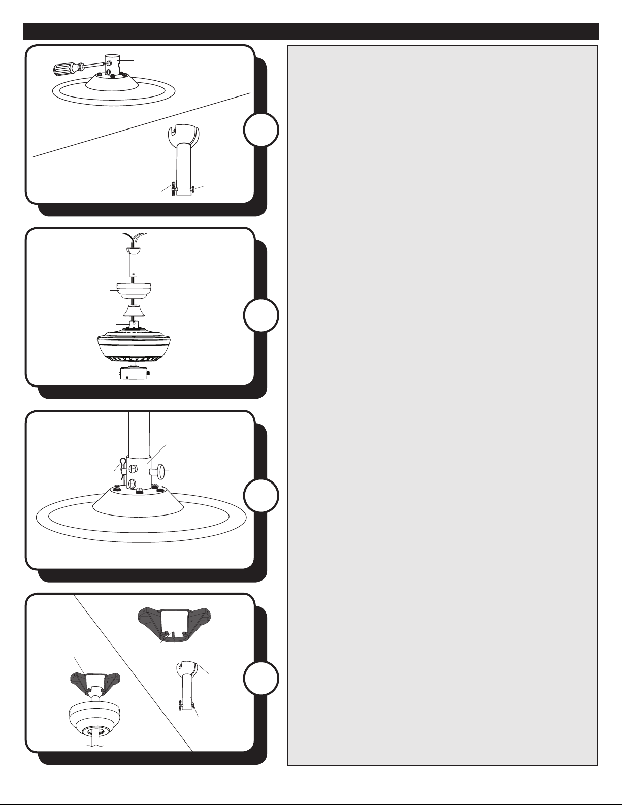
1
1. Turn OFF the electrical power at the main fuse or circuit
breaker.
4
Motor Screw
Motor Block
3
4. CLOSEMOUNT INSTALLATION (OPTIONAL)
a. Remove the canopy cover from the bottom of the
canopy.
b. Align the holes in the bottom of the canopy with the
screw holes in the top of the motor housing. The larger
holes in the canopy will encompass the preinstalled
closemount screws. Secure the canopy to the top of the
motor housing with the closemount screws from the
hardware kit.
c. Hang the fan on the hook of the mounting bracket.
Proceed to Step 9.
2
Mounting
Bracket Screw
2. Remove the canopy from the mounting bracket
by removing the two mounting bracket screws from
the round holes in the canopy. Then loosen the other
two mounting bracket screws from the L-shaped slots.
Retain the mounting bracket screws for later. Install the
mounting bracket to the outlet box (not included) using
the screws and washers provided with the outlet box.
Warning: To reduce the risk of re electric shock,
or personal injury, mount to the outlet box marked
“acceptable for fan support” and use the mounting screws
and washers provided with the outlet box.
3. Remove the motor screws from the underneath side of
the motor. Discard the motor blocks but keep the motor
screws for later.
If you wish to use the Downrod Mount (shown on page 3),
proceed to Step 5.
Closemount
Screw
Canopy
Mounting
Bracket
6Turn of the CenturyTM
ASSEMBLY INSTRUCTIONS
7
5
6
5. Loosen but don’t remove the set screws in the motor
adapter. Then remove the downrod pin and downrod clip
from the downrod.
6. Feed the wires coming from the motor adapter
through the adapter cover, canopy and downrod.
7. Insert the downrod into the motor adapter and
reinstall the downrod pin and downrod clip. Then
retighten the set screws.
Downrod Clip
Downrod
Canopy
Adapter Cover
Downrod Pin
Motor Adapter
Downrod
Downrod Clip
Motor Adapter
Motor Adapter
Downrod
Pin
8
8. With wiring extending out of the downrod, measure
8 inches of lead wire and cut the excess wire with wire
cutters (not included). Then strip 1/2” of insulation from
the end of each wire. Then, lift the downrod into the
mounting bracket. Rotate the downrod until the tab in the
mounting bracket is seated in the slot in the downrod ball.
Tab
Slot
Downrod
Mounting
Bracket

7Turn of the CenturyTM
ASSEMBLY INSTRUCTIONS
Black
White
Bare/Green
Wire Connector
Black
Blue
White
Green
11
10 10. Raise the canopy, ensuring that the two mounting
bracket screws are aligned with the L-shaped slots in
the canopy. Then turn the canopy clockwise until the
mounting bracket screws are completely engaged in
the L-shaped slots. Install the two previously removed
mounting bracket screws and star washers in the round
holes. Securely tighten all mounting bracket screws.
11. Attach the blades to blade arms using the blade
screws and washers from the hardware kit.
9. Use wire connectors to connect the fan wires to the
power supply wires according to the wiring diagram and
the following instructions:
• Connect the white wire from the fan to the white (neutral/
common) supply wire.
• Connect the black and blue wires from the fan to the
black (hot/power) supply wire.
• Connect the green wire from the fan to the bare/green
(ground) supply wire.
Note: If a second hot power wire is available from the
outlet box, connect it to the blue (light power) fan wire for
separate fan and light switches.
Important: After the connections have been made, the
wires should be turned upward and pushed carefully
up into the outlet box. Place the black and white wire
connections on opposite sides of the outlet box.
9
Canopy
L-shaped
Slot
Round
Hole
Blade
Arm
Blade
Mounting
Bracket Screw
Blade Arm
Blade Isolator Motor 12
12. Secure the blade arm and blade isolator to the
underneath side of the motor using motor screws
removed in Step 3. Completely secure each blade arm to
motor before moving to the next.
To install the fan without the light kit, skip to step 18.
8Turn of the CenturyTM
ASSEMBLY INSTRUCTIONS
14
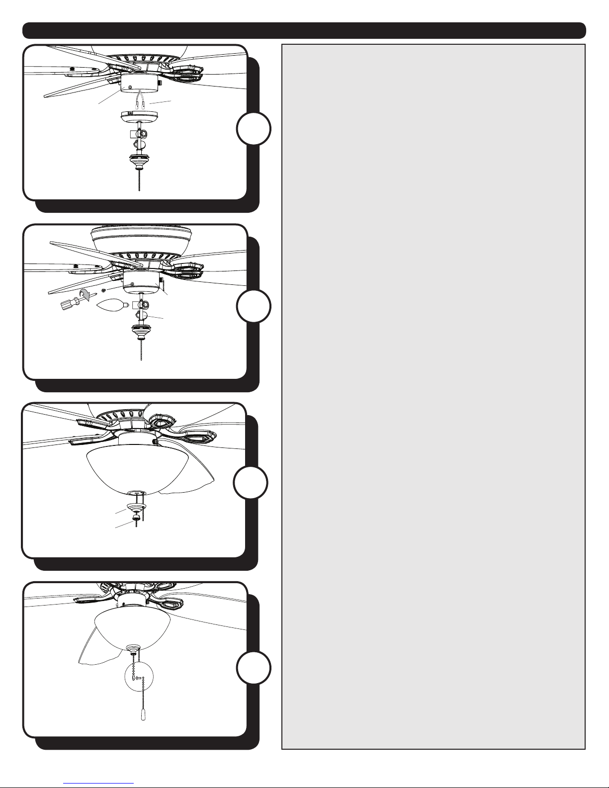
13. Remove the three switch housing screws from the
bottom edge of the switch housing. Connect the single-
pin connectors from the fan to the single-pin connectors
from the light kit -- black to blue and white to white.
14. Secure the light kit to the switch housing using the
three switch housing screws. Then install candelabra base
bulbs (60W max.) into the sockets in the light kit.
13
Switch
Housing
Single-pin
Connector
Switch Housing
Light Kit
15
15. Remove the nial cap and nial from the bottom of
the light kit. Feed fan pull chain coming from the switch
housing down through the grommet in the lower part
of the light kit. Then, feed the pull chains through the
appropriate holes in the nial plate and the hole in the
nial. Lift the nial plate up until it is ush with the glass
shade. Screw the nial onto the threaded rod of the light
kit tter.
Finial Cap
Finial
16. Attach pull chain extensions to the pull chains.
16
Pull Chain Extension
9Turn of the CenturyTM
ASSEMBLY INSTRUCTIONS
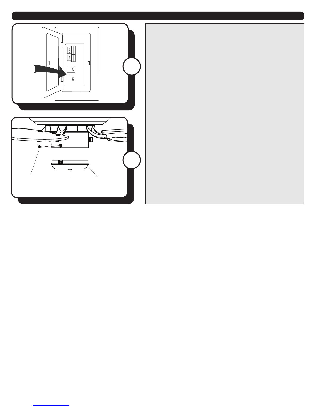
17
17. Restore the power at the main fuse or circuit breaker.
18. NO LIGHT KIT OPTION (OPTIONAL)
a. Remove the three switch housing screws from the lower
edge switch housing.
b. Remove the light kit from the switch housing cap by
removing the hex nut and washer from inside the switch
housing cap.
c. Install the switch housing cap to the bottom of the
switch housing with the three switch housing screws.
d. Insert plug button into center of switch housing cap.
e. Attach the pull chain extension (Step 18).
f. Restore the power at the main fuse or circuit breaker.
Switch
Housing Cap
Plug Button
Switch
Housing
Screw
18

10 Turn of the CenturyTM
OPERATING INSTRUCTIONS
1
2. Use the fan reverse switch, located on the switch
housing to optimize your fan for seasonal performance.
Using a ceiling fan will allow you to raise your thermostat
setting in summer and lower your thermostat setting in
winter without feeling a dierence in your comfort.
Note: Wait for the fan to stop before moving the reverse
switch.
In warmer weather, push the reverse switch down which
will result in downward airow creating a wind chill eect.
In cooler weather, push the reverse switch up, which will
result in upward airow that can help move stagnant, hot
air o the ceiling area.
1. The fan pull chain is located in the o-center hole in the
nial cap. It has four positions to control fan speed. One
pull is HIGH, two is MEDIUM, three is LOW and four turns
the fan OFF. The light pull chain is located in the center of
the nial. It turns the light ON and OFF.
2
Fan Pull
Chain
Light Pull
Chain
Questo manuale è adatto per i seguenti modelli
1
Indice


