Launch CCH201 Manuale utente

SPRAY BOOTH USER MANUAL
I
CHAPTER 1 GENERALINTRODUCTION ................................................................................................................. - 1 -
1.1 GENERALINTRODUCTION ....................................................................................................................................- 1-
CHAPTER 2 SPRAY BOOTH DESCRIPTION ............................................................................................................ - 2 -
2.1 THE STRUCTION DESCRIPTION...................................................................................................................... - 2 -
2.1.1THE MAIN ROOM ...........................................................................................................................................- 3-
2.1.2 GENERATOR PART.....................................................................................................................................- 6-
2. 1.3 CONTROL PANEL ......................................................................................................................................- 7-
2. 1.4 SOME OPTIONAL PARTS............................................................................................................................- 9-
2.2 THE PRINCIPLE OFTHE SPRAYBOOTH............................................................................................................ - 10 -
2.2.1SPRAYPAINTING PHASE...................................................................................................................................- 10 -
2.2.2DRYING PHASE ...............................................................................................................................................- 11 -
2.3 TECHNICALPARAMETER DIFFERENCE............................................................................................................. - 12 -
CHAPTER 3 THE INSTALLATION OF THE SPRAY BOOTH......................................................................................... - 13 -
3.1 THE INSTALLATION ENVIRONMENTAL CHARACTERISTICS ........................................................................... - 13 -
3.2 SOME NECESSARYTOOLS........................................................................................................................... - 14 -
3.3 INSTALLATION METHODSAND STEPS........................................................................................................... - 15 -
3.3.1 Basement installation................................................................................................................................-15-
3.3.2 Main room installation............................................................................................................................... - 16 -
3.3.3 Ceiling Installation.................................................................................................................................... - 19 -
3.3.5 Generator Installation ............................................................................................................................... - 23 -
3. 3.6 Control System Installation....................................................................................................................... - 25 -
CHAPTER 4 TESTAND OPERATION........................................................................................................................ - 29 -
4.1 PREPARATION BEFORE ................................................................................................................................-29-
4.1.1 PREPARATION BEFORE TESTINGAND OPERATION ............................................................................... - 29 -
4.1.2ATTENTION BEFORE TESTINGAND OPERATION.................................................................................... - 29 -
4.1.3 TEST THE ROTATION OF THE BLOWER .................................................................................................. - 29 -
4.1.4TEST THE DAMPER SYSTEM................................................................................................................... - 29 -
4.2ATTENTION NORMS ...................................................................................................................................... - 29 -
4.3 OPERATION............................................................................................................................................... - 30 -
4.3.1 PAINTING STATION ..................................................................................................................................- 31 -
4.3.2 DRYING STATION.....................................................................................................................................- 31 -
4.3.3 MACHINE STOP.......................................................................................................................................- 32 -
Contents

SPRAY BOOTH USER MANUAL
II
CHAPTER 5 MAINTENANCEAND REPAIR............................................................................................................. - 33 -
5.1 ORDINARYMAINTENANCE............................................................................................................................ - 33 -
5.2 ORDINARYMAINTENANCE INSTRUCTION..................................................................................................... - 33 -
5.3 SOME SPARE PARTS FOR MAINTENANCE .................................................................................................... - 34 -
CHAPTER 6 PACKING,SHIPPINGAND STORAGE ................................................................................................. - 35 -
6.1 PACKING....................................................................................................................................................... - 35 -
6.2 SHIPPING................................................................................................................................................... - 36 -
6.3 STORAGE...................................................................................................................................................... - 36 -
APPENDIX I : MALFUNCTIONAND REMEDY............................................................................................................ - 37 -
APPENDIX Ⅱ : INSTALLATION DRAWING (ATTACHED FILE)

SPRAY BOOTH USER MANUAL
- 1 -
Chapter 1 General Introduction
1.1 General Introduction
-Read the manual carefully before proceeding to start the booth.
-This manual has the aim of supplying the user all the necessary information so that,
besides a correct use of the booth, he is able to use it in the most auto and secure
possible way.
-This manual is suitable for our different kinds of standard spraying/baking booth.Such as
CCH101,CCH201 and other similar nonstandard model. we sellect CCH201 as a sample to give
the instruction about the spraying/baking booth in this manual,also we will make some explaintion for
some special parts in the following chapter.
-It is including the Technical aspect, Function, Machine stopper, Maintenance, Spare parts and Safety.
-Before carrying out any operation on the Booth, the Operators and the Qualified Technicians have to
read the instructions contained in the present publication carefully.
-If there is any doubt on the correct interpretation of the instructions, will consult our technical
department for the necessary explanations for you.
-The manual is an integral part of the Booth, it has to be taken care of by the buyer, it
has to be positioned in the immediate vicinity of the Booth, inside a special container
and, above all, protected from liquids and anything that is liable to jeopardize its
legibility.
-In the case of deterioration the construction firm will be happy to send another copy. in such a case it
is necessary to communicate to the technical office the characteristic data stamped on the special
identification nameplate. The manual has to stay with the machine in the event that it is sold..
-The contents of the present manual conform to the directive 2006/42/EC and any consequent
modifications.Normanlly we make the spray booth with some electrical components without CE
certificate.And remark that if you need CE certificated make.
-Data and drawings are only illustrative; the builder, having a pacific of constant development and
updating of the product, may make changes without any warming. It is forbidden for anyone to divulge,
modify or use this manual for personal reasons.

SPRAY BOOTH USER MANUAL
- 2 -
Chapter 2 Spray Booth Description
2.1 The Struction Description
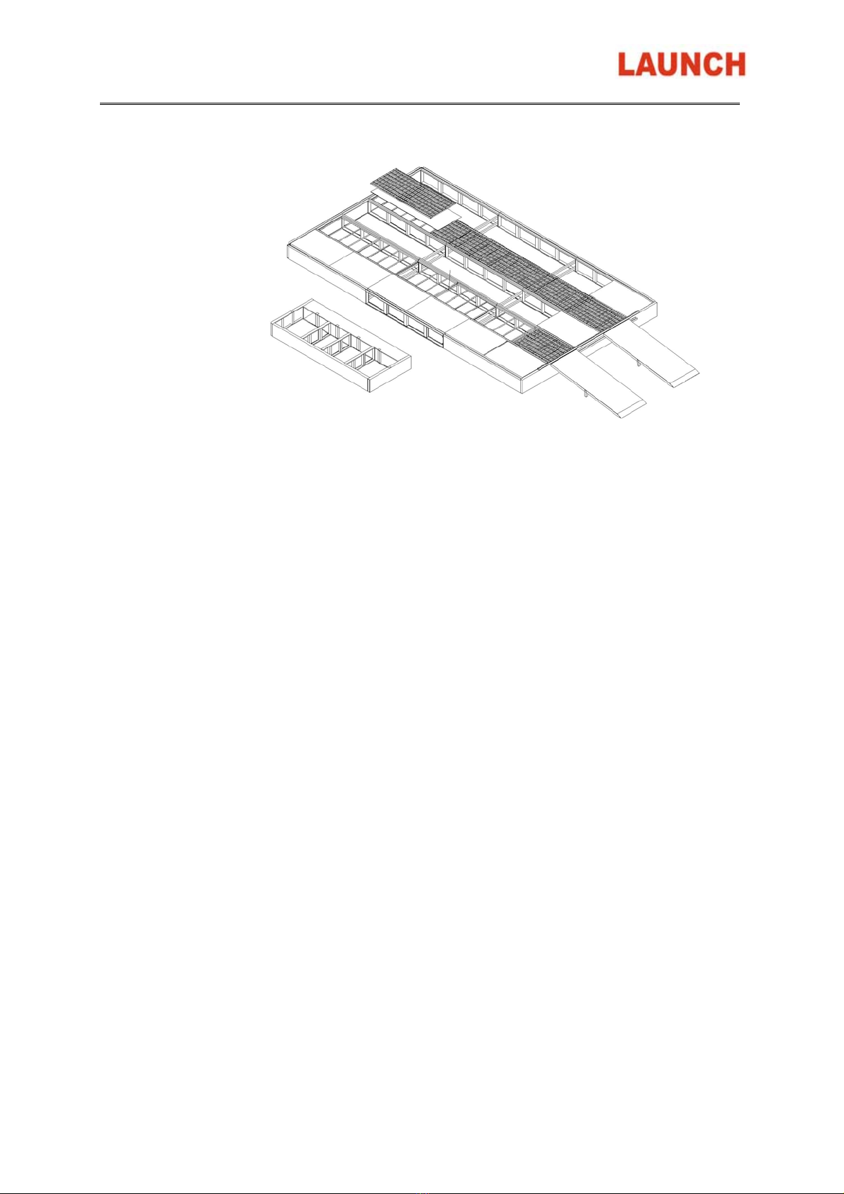
The spray booth is composed of the following parts:( shown in Fig.2.1)
Fig. 2.1
1)The main room:
-The base parts: Side metal panel,Back metal panel,Front metal panel,Middle supporting,Strenthen
bar for basement,Support net for filter,Galvanization air block panel,Floor filter grids,Ramp for auto
enter.
-The body parts: wall board(20) with or without side light,front door(19) with (including horizontal
boardand stand board,safe door(17),surround pieces of wall board ect.
-The top parts(air cabint) : top sealed board(5),lighting frame(2),filter slot panel,supporting for the
filter,roof supporter beam(4,6),filter,roof cover(1).
-Ramp(18):grids style or vein board style.
2)Generator parts
-Bottom of heat-air generator
-Middle frame of generator(13) :including the intake fansr and heat exchanger
-Burner(14),diesel burn for standard model and gas burner for optional.
-Top-frame for generator(12)、the connection part between top frame and air cabint

SPRAY BOOTH USER MANUAL
- 3 -
-Damper(11) for change between painting and baking system.
-Exhaust system: exhaust fan with pre-filter(9),Active carbon environment system as option(11)
-Smoke tube(15):connect with heat-exchanger,take the heat out.
-Air duct(7):exhaust duct is necessary and intake duct as option.
3)Oil tank with frame.
4)Control system(16):control the motor,burner,light system ect.
2.1.1 The Main Room
The spray painting environment is the closed place when the spray painting and the drying process is
carried out. it is divided into the following parts:
1)Side walls
The side walls are necessary to isolate the spray painting environment from the outside,both from the
thermal and acoustic point of view, and above all so as not to disperse the paint and solvents residue into
the environment, it is formed by: (shown in Fig.2.2)
Fig 2.2
-Side walls made of panels, with a thickness of 50 mm, modular types with tongue and groove
jointed,inserts with added seals. The thermic insulation of the spray painting environment is warranted
by the layer of expanded polyurethane or rock wool contained in the panels.
-Back walls, panels made of the same type as the side walls.
-Metal covers up the wall, are necessary for the up cover of the walls,which make each panel connect
together and easy to install the ceilling cover.
-Back corners, that are necessary for the connection between the side walls and the back wall.
2)Front walls
The front wall of the booth is composed of : (shown in Fig.2.3)

SPRAY BOOTH USER MANUAL
- 4 -
Fig.2.3
-The header horrizontal panel, is necessary for the plenum chamber and as a closure of the head part
of the front wall.
-Maid door with the glass windown, for the entry-exit of the operator, equipped with a spring release
opening.
-Side erect panel,is necessary to support the maid door and connect to the side wall panel.
-The installed fitting parts:such as the door lock,handle,hinges,connection bar for horrizontal panel and
erect panal.
3)Iumination system
-The intemal illumination is warranted by the overhead lights ( shown in Fig.2.4 ) inserted into the top
of the side panels, positioned at an angle of 45°to warranty a sufficient and uniform illumination.
Fig. 2.4

SPRAY BOOTH USER MANUAL
- 5 -
-The overhead lights are steel plates coated with paint ,in which four neon holders are positioned,
each of which fits four neons of 36 W, the neons are isolated from the spray painting environment by
panes of glass as the same type ot it used for the doors.
-In order to reach the better illustration effect,we usually install the side light in the side wall, the neons
are isolated from the spray painting environment by panes
4) Ceiling
The ceiling acts as both a cover for the spray painting environment and supporting for the air filters at the
entrance, it is composed of: (shown in Fig.2.5)
Fig.2.5
-Top lights, including the neons of the illumination of the booth, they are the parts of the air cabin.
-The filter frame, which are hanged with the top sealing panel.
-Roofs, they are plates of zinced plate that are necessary for the cover of the booth.
-The iron supporting beams, intercross by horrizontal beams and longitudinal beams,which are used
for supporting the ceiling.
-Top sealing panel is installed on the supporting beams.And the top sealing pannel are necessary to
cover the ceiling and hold up the filter frame
5)basement
The basement serves as a plenum chamber which lead the exiting air from the booth. It is composed
of(shown in Fig.2.6)
SPRAY BOOTH USER MANUAL
- 6 -
Fig.2.6
-Basement, made of front panel,back panel,side panel,middle supportor and strengthen bar placed
longitudinally and connected together. The pieces composing the basement are made of zinced
pressure folded plates.
-Floor filter supported frame and panel placed under the filter,the side rows and middle row with the
panel for keeping air off when all rows grids as optional. And the No 2 and No.4 rows with the
supported frame for air ventination.
-Floor filter,is necessary for painting filtration.Usuallly cover row of No.2 and No.4 with the floor
filter.And cover all five rows with floor filter when all grids as optional.
-Grids, that are inserted in the basement necessary for the flooring. There are five rows in total,Row 2
and Row Four should be the grids,and Row 1,Row 3 and Row 5 should be vein boards. but row No.2
and No.4 in the area in which the air is aspired the grids are only used, in order to allow the air to
pass.
2.1.2 Generator Part
The generator unit is necessary to start the forced ventilation needed for an optimal aerification and a
homogeneous distribution of the paint to produce the quantity of heat necessary for the drying process.All
the components of the generator unit are to be found in a closed booth . And the spray painting booth
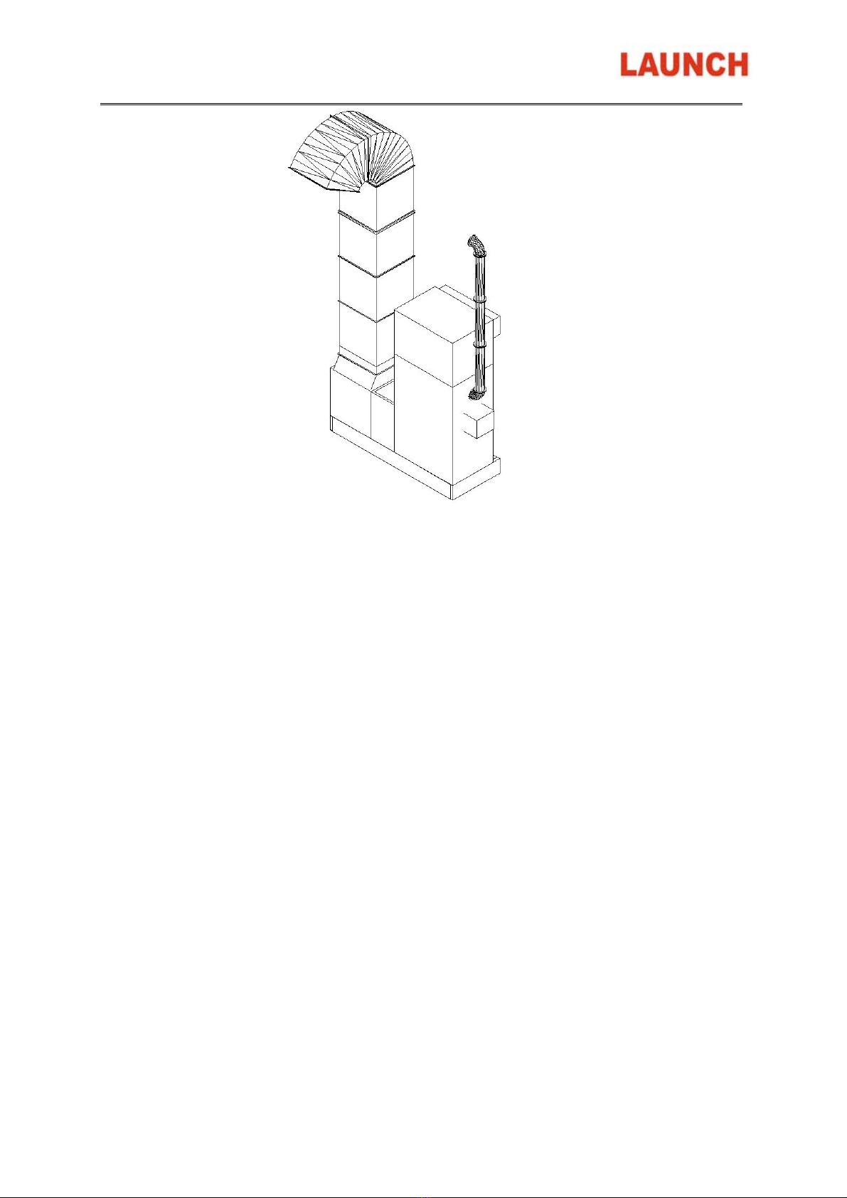
consisting of (shown in Fig.2.7)
SPRAY BOOTH USER MANUAL
- 7 -
Fig. 2.7
-Connector, for the connection between the generator unit booth and the spray painting
environment.Anti-vibration coupling in canvas is option so that the mechanical vibrations produced by
the motor are not transmitted to their booth.
-Combustion room , equipped with a stainless steel heat changer and anti-exploding porthole as
optional.
-Burner: Riello Diesel oil burner for standard.And the gas burner for option.
-Centrifugal fan , action by an electric motor.
-Enter filter frame, for pre-filtering incoming air.
-Damper system, which is pneumatic drive.it is necessary to a partially recycle the air to be introduced
in the paintiing and drying process phase.
-Air duct: take the exhaust out of the working area.
-Chimney: take the exhaust heat out of the working area,is connect with flange.
-Active carbon environmental system as option
2. 1.3 Control panel
The control panel is composed of the following switches and indicators(Shown in Fig.2.8)

SPRAY BOOTH USER MANUAL
- 8 -
Fig.2.8
-Switch to block main doors
-Drying process Timer(2), it is necessary in order to regulate the drying process.
-Temperature meter(1), it is necessary to regulate the temperature of the air both for the spray painting
and drying process.
-Burner indicator(3), it indicates the burner is opertation or not.
-Burner Break down alarm(4), it alarms if there are something wrong about the burner.
-Light switch(6),turn on or turn off the up and side light.
-Emergence stop button (8),which can cut off the power when the emergence happen.
-Selector switch of Painting and drying process(7), allows the passage from the spray painting phase
to the drying process and rise temperature painting.
-Over load alarm(10), it alarms if the motor over-load or over-heat.
-Start button(9), press it when you want to start the fans.
-Power ON/OFF(11), turn the key when you want to start or close the power.
-Power Indicator(13), it indicates the power is on or off.
-Motor operation Indicator(12), it indicates the motor is on or off.
Indice
Altri manuali Launch Attrezzature da laboratorio

Manuali Attrezzature da laboratorio popolari di altre marche


Agilent Technologies
Agilent Technologies 5800 ICP-OES Manuale utente

Endress+Hauser
Endress+Hauser Cleanfit CPA875 Manuale utente

NI
NI PXI-5422 Manuale

Collomix
Collomix Aqix Manuale utente

SPEX SamplePrep
SPEX SamplePrep 6875 Freezer/Mill Series Manuale utente

Ocean Insight
Ocean Insight FLAME-NIR+ Manuale utente


