Leuze electronic GmbH + Co. KG In der Braike 1 D-73277 Owen Tel. +49 (0) 7021 573-0 CRT448… - 02
Teach-in of color gradients
Notice on color scan:
The color scan serves to teach in entire color gradients or to teach in objects with strongly fluctuating scanning ranges which
cannot be detected with a tolerance level. To scan in color gradients of different objects, one object can be scanned in per
channel. By connecting the output channels via an OR function in the downstream control, color gradients of up to three different
objects can be represented as a color scan.
Special function
1. Start setting mode
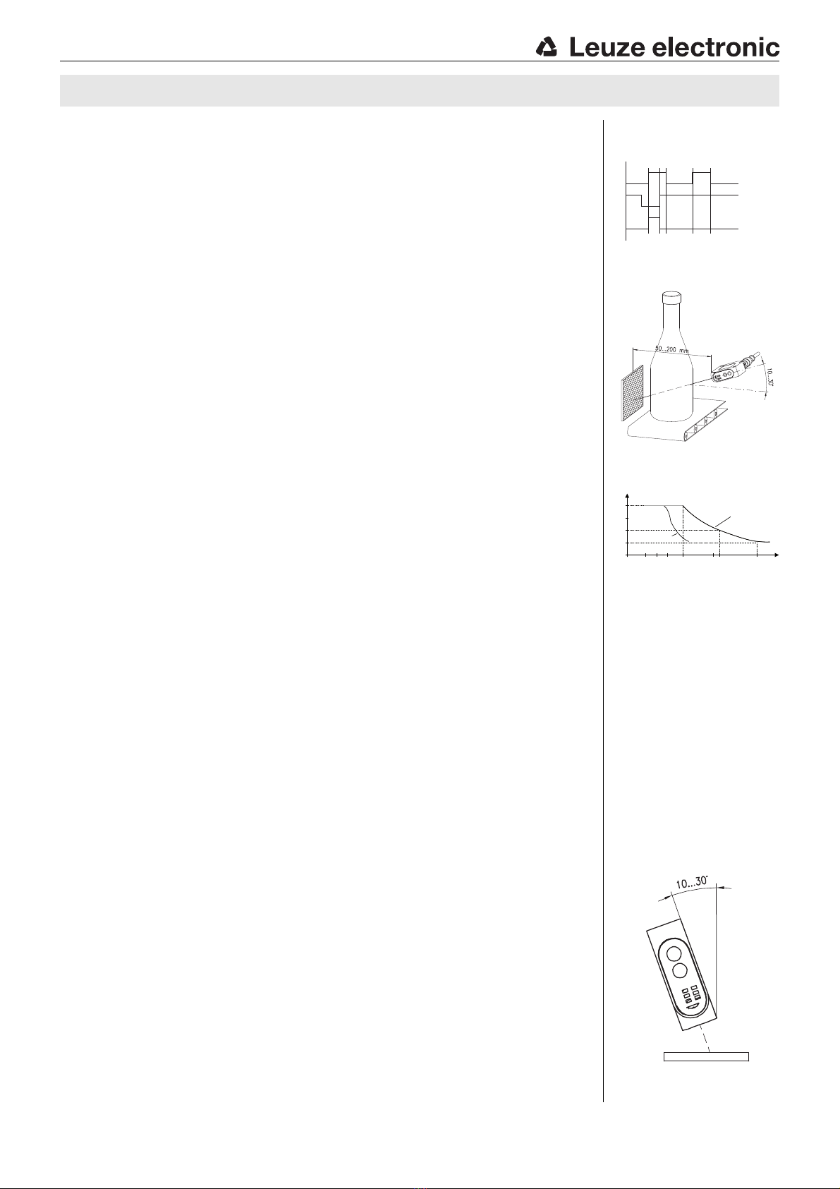
Position object to be detected within the scanning range
(make sure it is tipped 10-30°).
Press SET BUTTON for 3s >> green LED goes out and Ch. 1 illuminates yellow
(locking input open or 0 volt).
2. Select color scan function
With , select one of the color channels (Ch. 1, Ch. 2 or Ch. 3).
(Do not select position Ch. 1+Ch. 2+Ch. 3).
3. Scan color range + exit setting mode
Press SET BUTTON and hold it down, green LED blinks after 10s.
The color scan function is active. The sensor now permanently learns the colors which it "sees", provided the SET BUTTON
remains pressed. By moving the detected object, all colors are scanned which occur on the white light spot of the sensor.
Release SET BUTTON to end the scanning process.
The sensor is immediately ready to use again.
Function test by checking if yellow LED of the assigned output channel illuminates.
1. Start setting mode
Press SET BUTTON for 3s >> green LED goes out and Ch. 1 illuminates yellow.
(Locking input open or < 3 volt).
2. Select special function
With , select position Ch. 1+Ch. 2+Ch. 3. (all three LEDs illuminate).
3. Confirm selection
With SET BUTTON (press for 3s), confirm setting >> first red LED (Tol. 1) illuminates.
4. Select special function
With , select the desired special function.
Notices on special functions
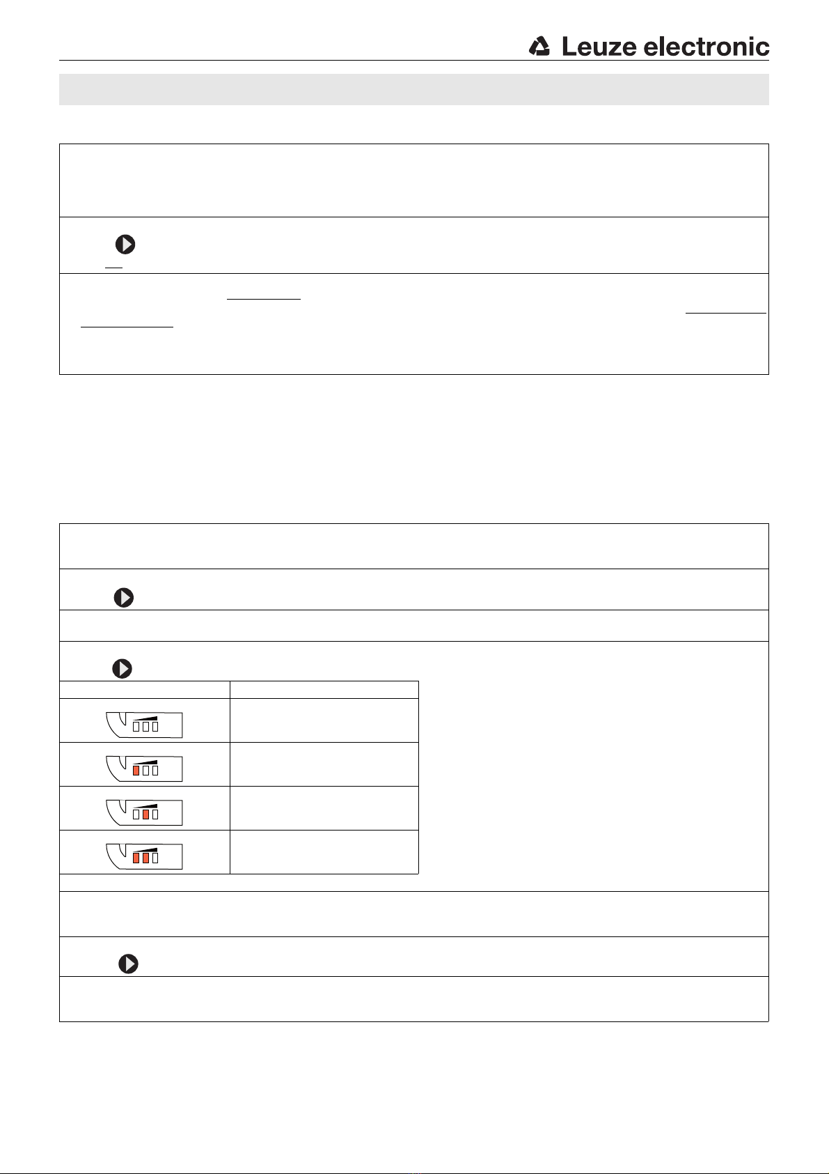
Tol. display Function characteristics a. Pulse stretching 50ms
Extension of the switching signals to 50ms. Acts on all
three outputs.
b. External teach-in *
Output Q3 becomes a teach-in input. When the HIGH
signal is present, a new color with tolerance 3 is taught on
channel 1. An acknowledgement signal (50ms) is output at
output Q2 after a successful external teach-in.
c. Factory settings
Resetting to factory settings. All special functions are
deactivated.
* only available for PNP types
Output menu
50ms pulse stretching
External teach-in *
Factory settings
5. Confirm selection
Press SET BUTTON (for 3s) to confirm the selected special functions. (For testing purposes: the selected special function
is indicated by the illuminated green LED).
6. Delete display
Press until all red LEDs go out.
7. Exit setting mode
Press SET BUTTON (for 3s) >> green LED illuminates.
The sensor is ready in the new operating mode.
To l .
To l .
To l .
CRT448 Color sensors