
LG MW-30LZ10 Manuale utente

LCD MONITOR
SERVICE MANUAL
CAUTION
BEFORE SERVICING THE CHASSIS,
READ THE SAFETY PRECAUTIONS IN THIS MANUAL.
CHASSIS : MF-02HA
MODEL : MW-30LZ10
website:http://biz.LGservice.com
e-mail:http://www.LGEservice.com/techsup.html
Aug., 2002
Printed in KoreaP/NO : 3828VD0120B

- 2 -
CONTENTS
Contents .................................................................................................. 2
Safety Precautions ..................................................................................3
Adjustment Instruction ............................................................................4
Troubleshooting .......................................................................................6
Printed Circuit Board ...............................................................................7
Block Diagram.........................................................................................11
Exploded View ...................................................................................... 16
Exploded View Parts List.......................................................................17
Replacement Parts List ........................................................................ 18
SVC. Sheet .................................................................................................
- 3 -
SAFETY PRECAUTIONS
Many electrical and mechanical parts in this chassis have special safety-related characteristics. These parts are identified by in
the Schematic Diagram and Replacement Parts List.
It is essential that these special safety parts should be replaced with the same components as recommended in this manual to
prevent X-RADIATION, Shock, Fire, or other Hazards.
Do not modify the original design without permission of manufacturer.
General Guidance
An lsolation Transformer should always be used during
the servicing of a receiver whose chassis is not isolated from
the AC power line. Use a transformer of adequate power rating
as this protects the technician from accidents resulting in
personal injury from electrical shocks.
It will also protect the receiver and it's components from being
damaged by accidental shorts of the circuitary that may be
inadvertently introduced during the service operation.
If any fuse (or Fusible Resistor) in this TV receiver is blown,
replace it with the specified.
When replacing a high wattage resistor (Oxide Metal Film
Resistor, over 1W), keep the resistor 10mm away from PCB.
Keep wires away from high voltage or high temperature parts.
Due to high vacuum and large surface area of picture tube,
extreme care should be used in handling the Picture Tube.
Do not lift the Picture tube by it's Neck.
Before returning the receiver to the customer,
always perform an AC leakage current check on the exposed
metallic parts of the cabinet, such as antennas, terminals, etc.,
to be sure the set is safe to operate without damage of
electrical shock.
Leakage Current Cold Check(Antenna Cold Check)
With the instrument AC plug removed from AC source,
connect an electrical jumper across the two AC plug prongs.
Place the AC switch in the on positioin, connect one lead of
ohm-meter to the AC plug prongs tied together and touch other
ohm-meter lead in turn to each exposed metallic parts such as
antenna terminals, phone jacks, etc.
If the exposed metallic part has a return path to the chassis, the
measured resistance should be between 1MΩ and 5.2MΩ.
When the exposed metal has no return path to the chassis the
reading must be infinite.
An other abnormality exists that must be corrected before the
receiver is returned to the customer.
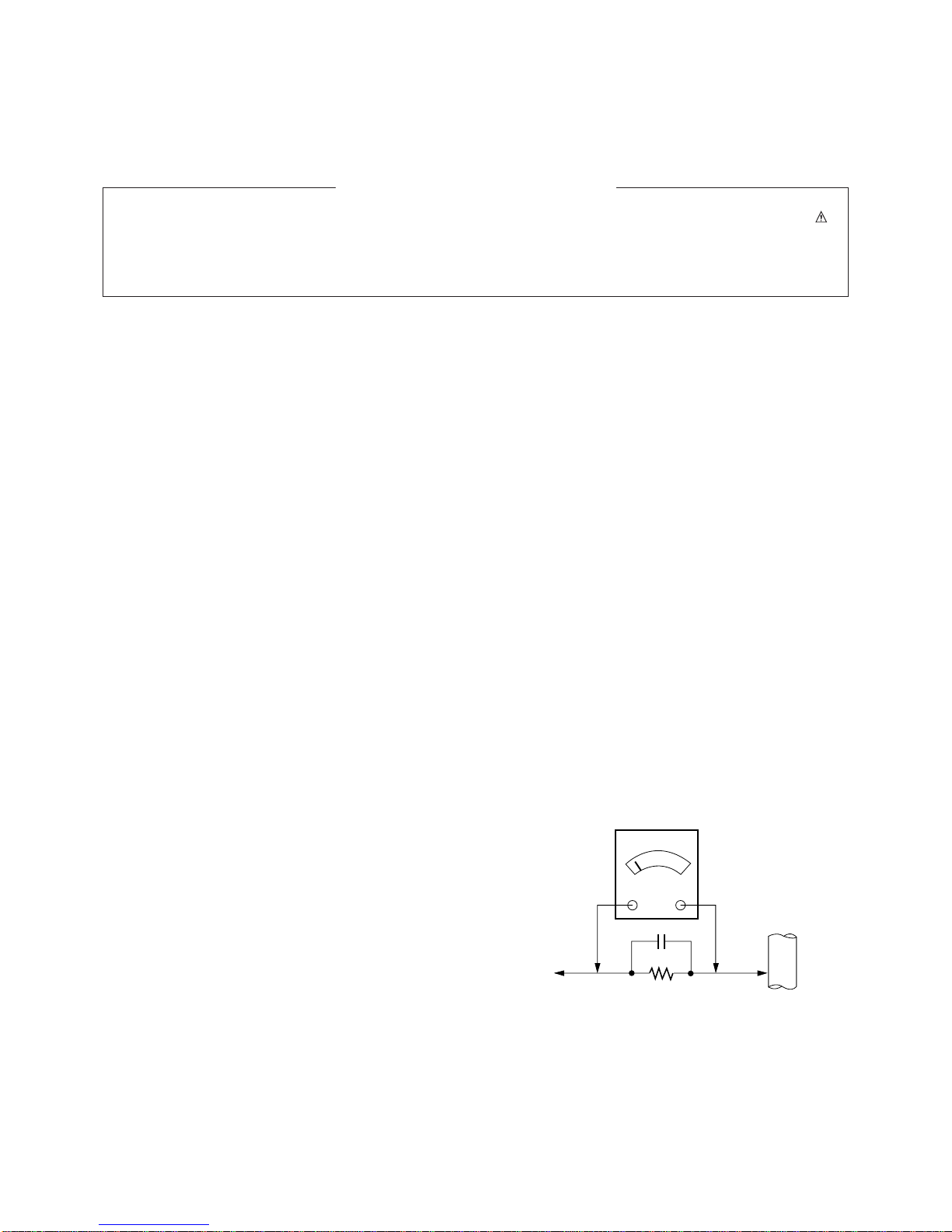
Leakage Current Hot Check (See below Figure)
Plug the AC cord directly into the AC outlet.
Do not use a line Isolation Transformer during this check.
Connect 1.5K/10watt resistor in parallel with a 0.15uF capacitor
between a known good earth ground (Water Pipe, Conduit, etc.)
and the exposed metallic parts.
Measure the AC voltage across the resistor using AC
voltmeter with 1000 ohms/volt or more sensitivity.
Reverse plug the AC cord into the AC outlet and repeat AC
voltage measurements for each esposed metallic part. Any
voltage measured must not exceed 0.75 volt RMS which is
corresponds to 0.5mA.
In case any measurement is out of the limits sepcified, there is
possibility of shock hazard and the set must be checked and
repaired before it is returned to the customer.
Leakage Current Hot Check circuit
1.5 Kohm/10W
To Instrument's
exposed
METALLIC PARTS
Good Earth Ground
such as WATER PIPE,
CONDUIT etc.
AC Volt-meter
IMPORTANT SAFETY NOTICE
0.15uF

- 4 -
1. Application Object
These instructions are applied to all of the MODELS of LCD
MONITOR, MF-02HA.
2. Notes
(1) Because this is not a hot chassis, it is not necessary to use
an isolation transformer. However, the use of isolation
transformer will help protect test instrument.
(2) Adjustment must be done in the correct order. But, it can
be changed in consideration of mass production.
(3) The adjustment must be performed in the circumstance of
25±5°C of temperature and 65±10% of relative humidity if
there is no specific designation.
(4) The input voltage of the receiver must keep 220V, 60Hz in
adjusting.
[Input voltage is possible from 85V to 260V because the
power voltage applied to this chassis is Wide-Range. But,
adjustment should be operated in 220V/60Hz if there is no
specific designation.
(5) The receiver must be operated for about 15 minutes prior
to the adjustment.
¤After receiving 100% white pattern(06CH), the receiver
must be operate prior to adjustment.(Or white condition
in HEAT-RUN mode)
¤ŁEnter into HEAT-RUN mode
- Select HEAT RUN OFF by pressing ADJ button on
Remote Control for adjustment.
- Press the VOL + button in HEAT-RUN OFF.
(OSD displays HEAT-RUN WHITE and screen
displays 100% full WHITE PATTERN)
[Set is activated HEAT-RUN without signal generator
in this mode.
[ Single color pattern of HEAT-RUN mode can be used
to check PANEL.(RED/BLUE/GREEN)
[Caution] If you turn on a still screen more than 20 minutes
(especially, Digital pattern[13 CH], Cross Hatch
Pattern[09CH]), a afterinage may be occur in the black
level part of the screen.
3. Adjustment Items
3-1. Whole Assembly Adjustment
(1) White Balance Adjustment
(2) SUB-BRIGHT Adjustment : Sub-Bright adjustment in LCD
panel is not necessary. Do not adjust sub-bright if there is
no specific designation.
(3) RGB CUT-OFF Adjustment : Under examination about
auto adjustment which correspond to the new Rembrandt-
1A.
3-2. EDID (The Extended Display
Identification Data) Adjustment
(1) This is the function that is made for the realization of “Plug
and Play” which makes possible to use the user
environment right after reorganization by communicating
with monitor automatically.
(2) EDID DATA for DVI of MF-02HA
EDID table =
00 01 02 03 04 05 06 07 08 09
_________________________________
000 | 00 FF FF FF FF FF FF 00 1E 6D
010 | D7 3A 01 01 01 01 33 0B 01 01
020 | 81 40 26 96 08 B7 FB A1 56 48
030 | 98 24 13 48 4B AF EF 00 81 00
040 | 31 59 45 59 61 59 81 80 71 4F
050 | 01 01 01 01 BC 34 00 98 51 00
060 | 2A 40 10 90 13 00 40 26 00 00
070 | 00 1E 00 00 00 FC 00 4D 57 20
080 | 33 30 4C 5A 31 30 0A 20 20 20
090 | 00 00 00 FD 00 3C 78 1F 5B 10
100 | 00 0A 20 20 20 20 20 20 D5 09
110 | 80 A0 20 E0 2D 10 10 60 A2 00
120 | EE F0 75 00 00 18 00 BD
(3) EDID DATA for RGB of MF-02HA
EDID table =
00 01 02 03 04 05 06 07 08 09
__________________________________
000 | 00 FF FF FF FF FF FF 00 1E 6D
010 | D7 3A 01 01 01 01 33 0B 01 01
020 | 1E 40 26 96 08 B7 FB A1 56 48
030 | 98 24 13 48 4B AF EF 00 81 00
040 | 31 59 45 59 61 59 81 80 71 4F
050 | 01 01 01 01 BC 34 00 98 51 00
060 | 2A 40 10 90 13 00 40 26 00 00
070 | 00 1E 00 00 00 FC 00 4D 57 20
080 | 33 30 4C 5A 31 30 0A 20 20 20
090 | 00 00 00 FD 00 3C 78 1F 5B 10
100 | 00 0A 20 20 20 20 20 20 D5 09
110 | 80 A0 20 E0 2D 10 10 60 A2 00
120 | EE F0 75 00 00 18 00 BD
(4) Refer to Service Manual related to EDID communication.
4. Whole Assembly Adjustment
<Caution> Each PCB Assy must be checked by Check JIG Set
before assemling.(Be careful about power PCB ASSY
which can give a fatal damage to the LCD Module)
4-1. White Balance Adjustment
(1) Required Equipment
Color analyzer(CA-100 or same production)
ADJUSTMENT INSTRUCTION
- 5 -
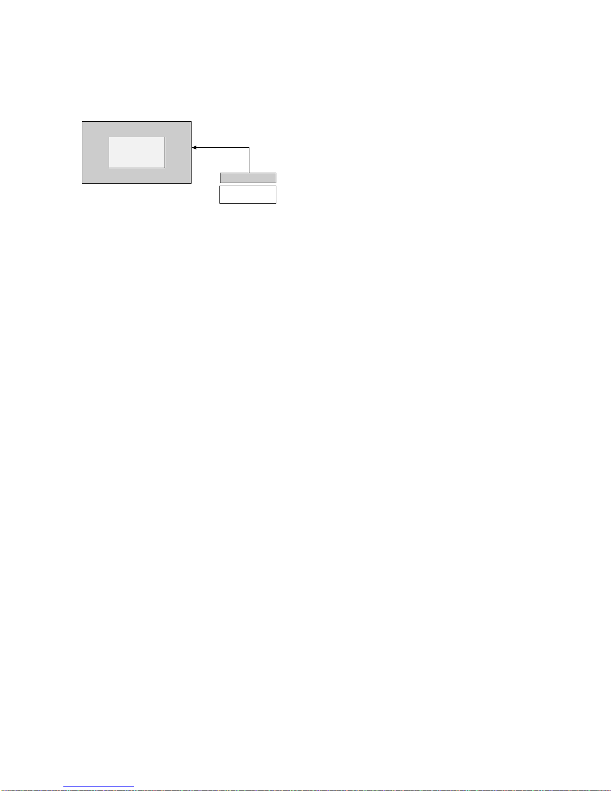
(2) Connection Diagram of Equipment for
Measuring (Automatic Adjustment)
Connect RS-232C to Adjustment Equipment and SET.
Automatization operating room has in charge of managing and
repairing about adjusting equipment.
Only adjust HIGH LIGHT and RGB input adjusts R-GAIN/G-
GAIN/B-GAIN automatically.
Automatic adjustment equipment decides the values of R-
GAIN/G-GAIN/B-GAIN by correcting color coordinates/white
balance and transmits them into SET and finally the SET
saves data values.
(3) White Balance Adjustment(Manual Adjustment)
¯Operate Zero Calibration of CA-100 and Sensor must be
stick completely to the surface of LCD module
¯Devide Manual adjustment into AV/PC and operate
adjustment by the following sequence.
¯Manual adjustment is a temporary method when automatic
adjustment is not correspondent.
1. AV W/B adjustment
1) Select WHITE PATTERN of HEAT RUN mode by
pressing ADJ button on Remote Control for adjustment
then operate HEAT RUN more than 15 minute
2) Supply pattern signal for WB adjustment in pattern
generator. (AV INPUT)
3) Low Light has no special adjustment.
4) To adjust High Light, stick sensor to 2th pattern(White),
select and adjust the AV GAIN by pressing INSTSRT
button on Remote Control for adjustment.
After select the R GAIN and G GAIN, enter Adjustment
Mode by pressing ENTER button and press the VOL +/-
Key and adjust it until color coordination becomes (B
GAIN is fixed)
color coordination : X=0.283±0.003, Y=0.296±0.003
color temperature : 9,350°K ± 500°K
5) Exit adjustment mode using Enter button.
2. PC W/B Adjustment
1) Select WHITE PATTERN of HEAT RUN mode by
pressing ADJ button on Remote Control for adjustment
then operate HEAT RUN more than 15 minute.
2) Supply pattern signal for WB adjustment in pattern
generator.(RGB1 INPUT)
3) Low Light has no special adjustment.
4) To adjust High Light, stick sensor to 2th pattern(White),
select and adjust the PC GAIN by pressing INSTSRT
button on Remote Control for adjustment.
After select the R GAIN and G GAIN, enter Adjustment
Mode by pressing ENTER button and press the VOL +/-
Key and adjust it until color coordination becomes (B
GAIN is fixed)
color coordination : X=0.283±0.003, Y=0.296±0.003
color temperature : 9,350°K ± 500°K
(R Gain is used to adjust X-coordinates while adjusting
and X-coordinates could be shortened when R Gain is
increased.
G Gain is used to adjust Y-coordinates while adjusting
andY-coordinates could be shortened when G Gain is
increased.)
5) Exit adjustment mode using Enter button.
3. Component (480p~1080i) Offset Adjustment
¯Use this adjustment when the Grayscale out of Ch13.
Pattern has red or blue while producing set.
¯This adjustment is used to remove the declination of
YPbPr Offset in AD9888.
1) Operate the adjustment after PC/AV White Balance
adjustment progress.
2) Select Ch.14 after connect DTV STB to Component
(480p~1080i) terminal and AV terminal.
3) When you press ADJ button twice on the R/C for
adjustment, the SET goes to DWI condition and Main
Window(right side)/Sub Window(left side) are set to AV
mode.
4) In this condition, adjust R with ‘DTV R OFFSET’ and B
with ‘DTV B OFFSET’ based on ‘foundation color(Gray)’
of Ch.14.
5) Exit adjustment mode using Enter button.
Window
MASTER or
QUANTUM DATA
COLOR
ANALYZER
TYPE;CA-100
RGB Signal Input
LCD MONITOR
High Light
450±70cd/m2
(Fig. 1) Connection Diagram of Automatic Adjustment
- 6 -
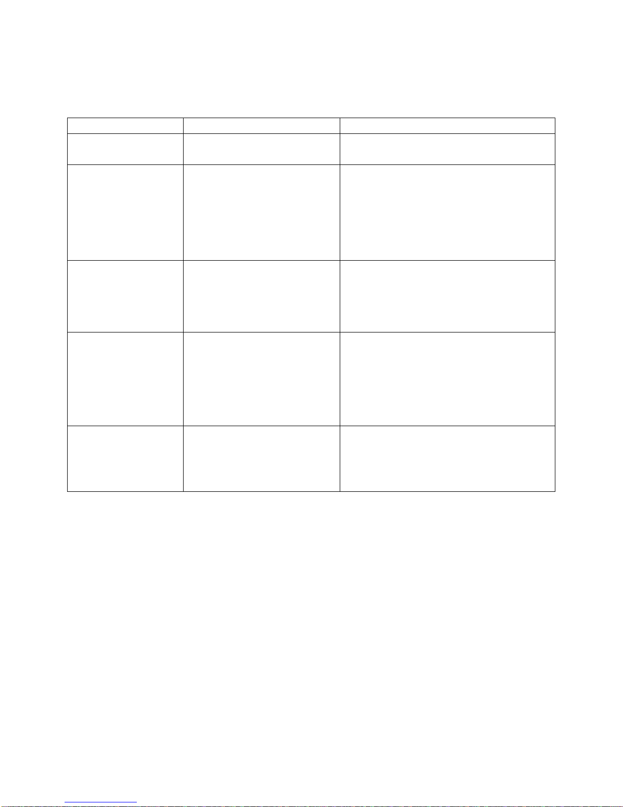
Symptom Cause Check Point
1) Check BD801, Q801, Q802, Q804
2) Check BD801, L801, L802, TH800, TH801
1) Check the second side parts and Pattern short
2) Check reverse input of PH801, D916, CR802
3) Check R941~R944 when the Pin Bias power no7. of
U902 is abnormal. (normal: 15V~25V)
- Replace U902(FAN7554) parts
- Check the error of Q804
4) Replace T803
1) Check the peripheral parts of 18V and Pattern short.
2) Check reverse input of D916(SB560)
3) No Input of L812 when both terminal voltage of C830
are low. (normal voltage: +24V)
- Replace U802(PQ1CG203) parts when there is no
error.
1) Check the peripheral parts of 5VS and Pattern short.
2) Check reverse input of D802, CR801
3) Check R937~R939 when the Pin Bias power no7. of
U903 is abnormal. (normal: 15V~25V)
- Replace U903(FAN7554) parts
- Check the error of Q802
4) Replace T802
1) Replace U901(MC33368D) when there is no error in
the peripheral parts.
- Check the error of Q801
2) Replace T801
1) Fuse open
2) Error of rectying circuit/EMI Filter
1) Short of output terminal
2) Input error of parts
3) Error of U902 and peripheral circuits.
4) Error of T803
1) Short of output terminal
2) Input error of parts
3) Error of U802 and peripheral circuits.
1) Short of output terminal
2) Input error of parts
3) Error of U903 and peripheral circuits.
4) Error of T802
1) Drop of output power due to the error
of PFC circuit.
2) Error of T801
1. No power from all outputs
2. No power from +24V/+12V
/+18V
3. No power from +18V
4. No power from +5VS
5. No power from +24V/+12V
/+18V in 110VAC Input
TROUBLESHOOTING
- 7 -
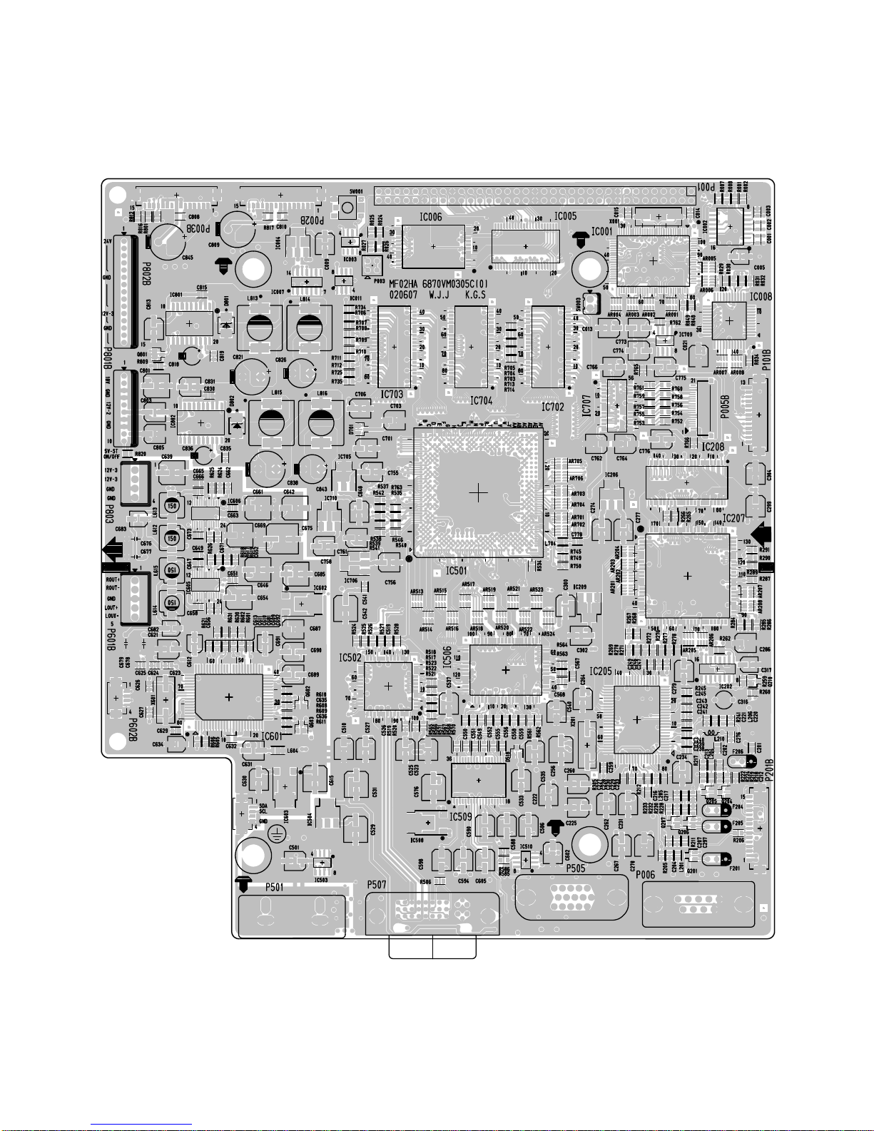
PRINTED CIRCUIT BOARD
MAIN(TOP)

- 8 -
MAIN(BOTTOM)

- 9 -
SIDE A/V(TOP)
SIDE A/V(BOTTOM)
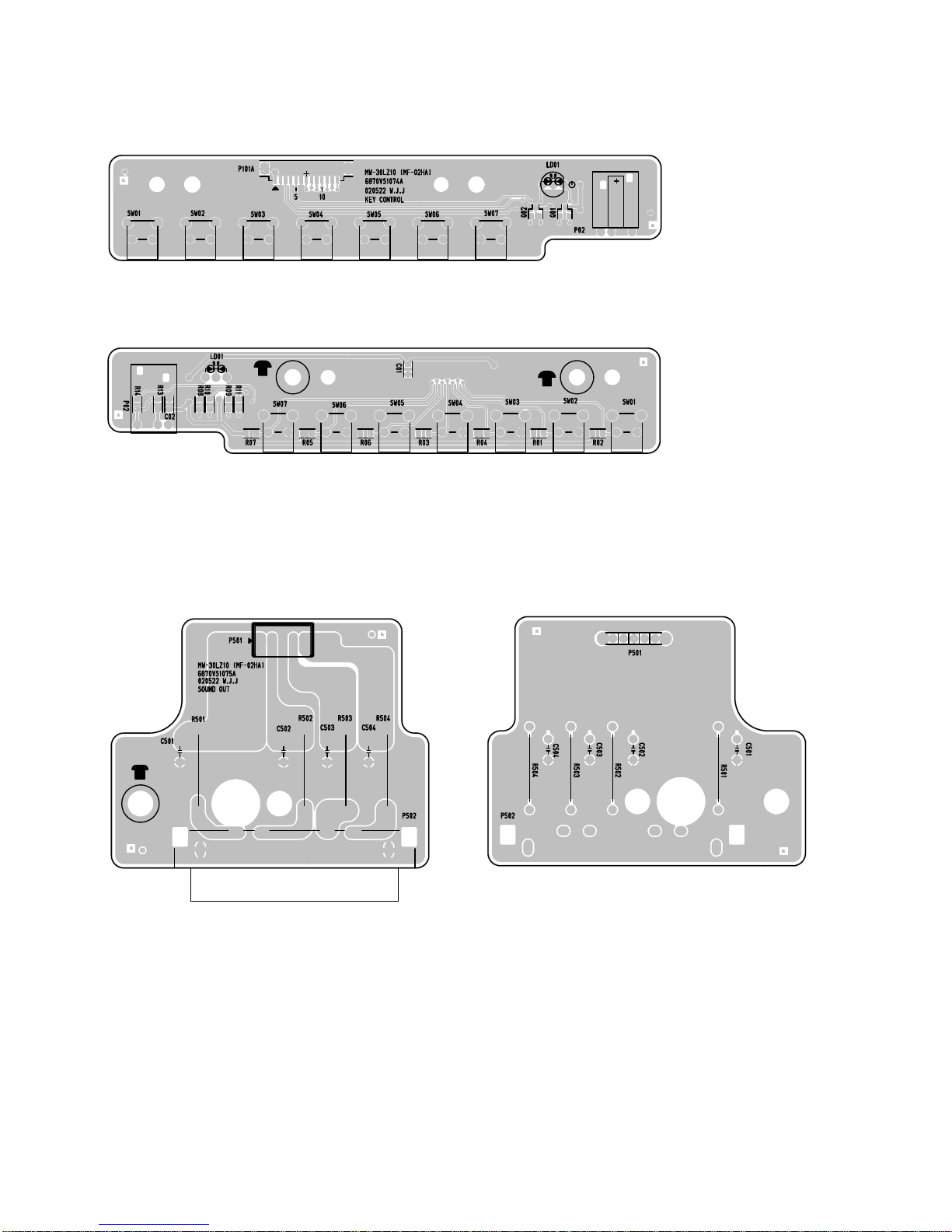
- 10 -
CONTROL(TOP)
POWER(TOP) POWER(BOTTOM)
CONTROL(BOTTOM)
Altri manuali per MW-30LZ10
1
Indice
Altri manuali LG Monitor


LG
LG 27BN650Y Manuale utente

LG
LG 50PG20 Series Guida all'installazione

LG
LG L1730SF Manuale utente

LG
LG 22MP65HQ Manuale utente

LG
LG 27QD58P Manuale utente

LG
LG 24GM79G-B.AUS Manuale utente

LG
LG 24BP55Q Manuale utente

LG
LG L1530TM Manuale utente

LG
LG UltraGear 27GN650P Manuale utente

LG
LG FLATRON M1710S Manuale utente


