
LG LSC27918SW Manuale utente
CAUTION
PLEASE READ CAREFULLY THE SAFETY PRECAUTIONS OF THIS MANUAL
BEFORE CHECKING OR OPERATING THE REFRIGERATOR.
REFRIGERATOR
SERVICE MANUAL
PUSHPUSH MODELS:
LSC27918SW
LSC27918ST

CONTENTS
WARNINGS AND SAFETY PRECAUTIONS ..........................................................................
1. SPECIFICATIONS ...............................................................................................................
2. PARTS IDENTIFICATION ...................................................................................................
3. HOW TO INSTALL REFRIGERATOR .................................................................................
4. HOW TO DISASSEMBLE AND ASSEMBLE......................................................................
5. MICOM FUNCTION .............................................................................................................
6. EXPLANATION FOR MICOM CIRCUIT ..............................................................................
7. ICEMAKER AND DISPENSER WORKING PRINCIPLES AND REPAIR............................
8. CIRCUIT ..............................................................................................................................
9. TROUBLE DIAGNOSIS ......................................................................................................
10. EXPLODED VIEW .............................................................................................................
3
4
5
6
9
12
20
36
39
40
78
- 2 -

Please observe the following safety precautions to use the
refrigerator safely and correctly and to prevent accident or
injury when servicing.
1. Be careful of an electric shock. Disconnect power cord
from wall outlet and wait for more than three minutes
before replacing PWB parts. Shut off the power
whenever replacing and repairing electric components.
2. When connecting power cord, please wait for more than
five minutes after power cord was disconnected from the
wall outlet.
3. Please check if the power plug is pressed by the
refrigerator against the wall. If the power plug was
damaged, it could cause fire or electric shock.
4. If the wall outlet is overloaded, it may cause a fire.
Please use a dedicated circuit for the refrigerator.
5. Please make sure the outlet is properly grounded.
Particularly in a wet or damp area.
6. Use standard electrical components.
7. Make sure hooks are correctly engaged.
Remove dust and foreign materials from the housing
and connecting parts.
8. Do not fray, damage, run over, kink, bend, pull out, or
twist the power cord.
9. Please check for evidence of moisture intrusion in the
electrical components. Replace the parts or mask with
insulation tape if moisture intrusion was confirmed.
10. Do not touch the icemaker with hands or tools to
confirm the operation of geared motor.
11. Do not suggest that customers repair their refrigerator
themselves. This work requires special tools and
knowledge. Non-professionals could cause fire, injury,
or damage to the product.
12. Do not store flammable materials such as ether,
benzene, alcohol, chemicals, gas, or medicine in the
refrigerator.
13. Do not put anything on top of the refrigerator,
especially something containing water, like a vase.
14. Do not put glass bottles with full of water into the
freezer. The contents will freeze and break the glass
bottles.
15. When you scrap or discard the refrigerator, remove the
doors and dispose of it where children are not likely to
play in or around it.
WARNINGS AND PRECAUTIONS FOR SAFETY
- 3 -
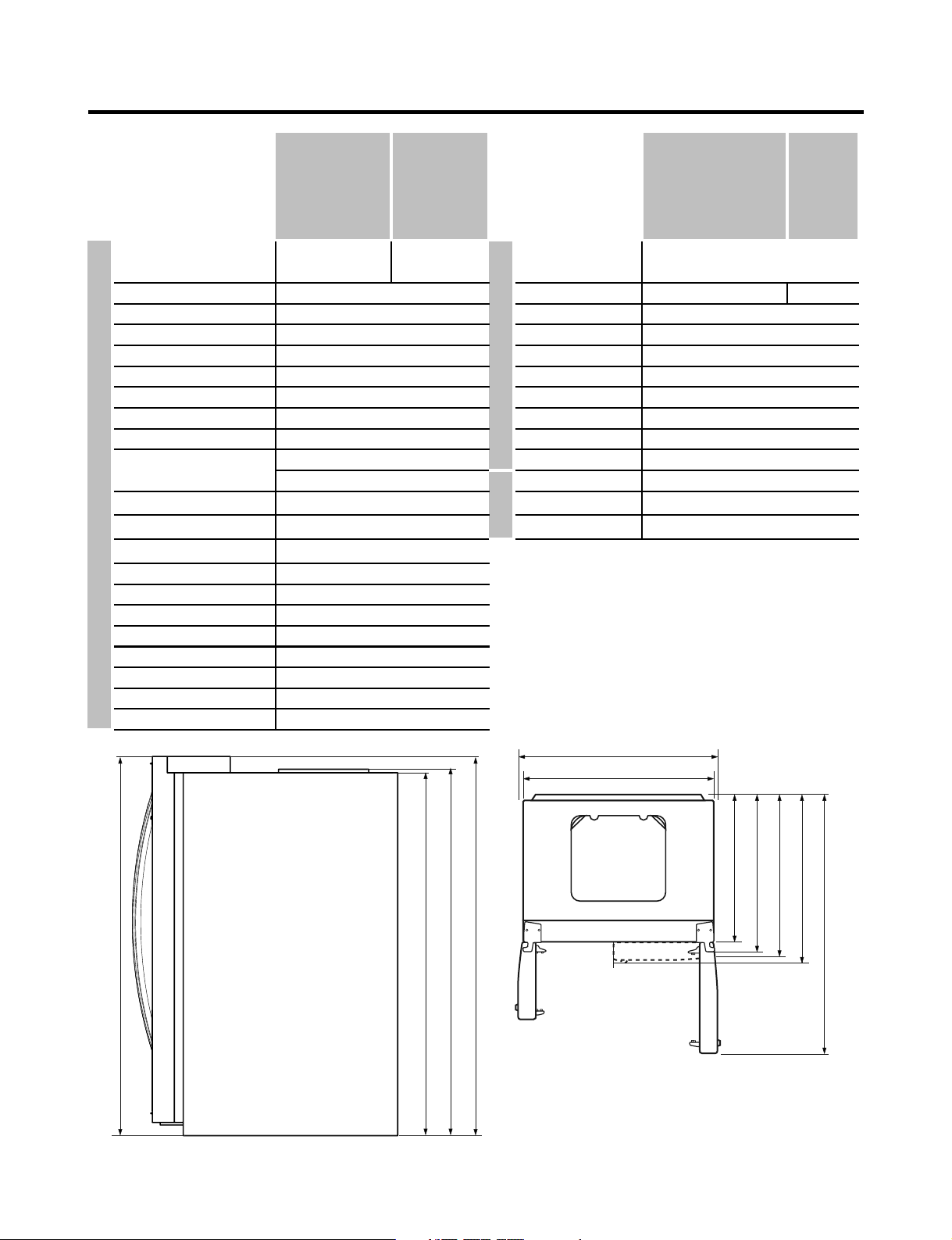
1. SPECIFICATIONS
- 4 -
724 mm (281/2
912 mm (35 in.)
779 mm (305/8 in.)
830 mm (325/8 in.)
891 mm (355/16 in.)
1261 mm (495/8 in.)
1741.5 mm (681/2 in.)
1746.5 mm (683/4 in.)
1771 mm (6911/16 in.)
1771 mm (6911/16 in.)
Front View Top View
29
/32
908 mm (35 in.)
11/16
LSC27918SW
LSC27918ST
MODELS
LSC27918SW
LSC27918ST
Super White Stainless
PCM Stainless
Lamp
Shelf
REFRIGERATOR
Handle Type
Display Graphic
Basket, Quantity
Ice Tray & Bank
SPECIFICATIONS
Case Material
Door Material
GENERAL FEATURES
Color
FREEZER
Anti-freezing Heater
Drier
2 Wire + 1 plastic
Yes (1) 40W/Blue
5 EA (Wire)
Yes
No
Yes (4) 40W/Blue
1 (Fix) + 2 (S/Out)
AUTO ICE MAKER+ SPACE PLUS
Embo (normal)
Vista
ICE PLUS
3 full + 1half
Heater, Sheath
13 - 70 Hours
Fin Tube Type
Lamp
Shelf
Tray meat
Egg Bank
Basket, Quantity
Defrosting System
First Defrost
Condenser
Lubricanting Oil
Defrost Cycle
Defrosting Device
Evaporator
ID Ø0.85
4 Hours
Capillary Tube
Cooling System
36 x 33 x 70 in
328.5 lbs
27 cuft
R134a
Fan Cooling
115 V / 60HzRated Rating
Water Tank Heater
Insulation
Compressor
Temperature Control
Heater Defrost
Cyclo, Pentane
MOLECULAR SIEVE XH-7
MICOM control
EGX90HLC COMBO Starting Type
Wire Condenser
Full Automatic
ESTER / ISO10 280ml
MODELS
SPECIFICATIONS
Capacity
Refrigerant
Net Weight
Dimensions
Temperate (N)Climate class
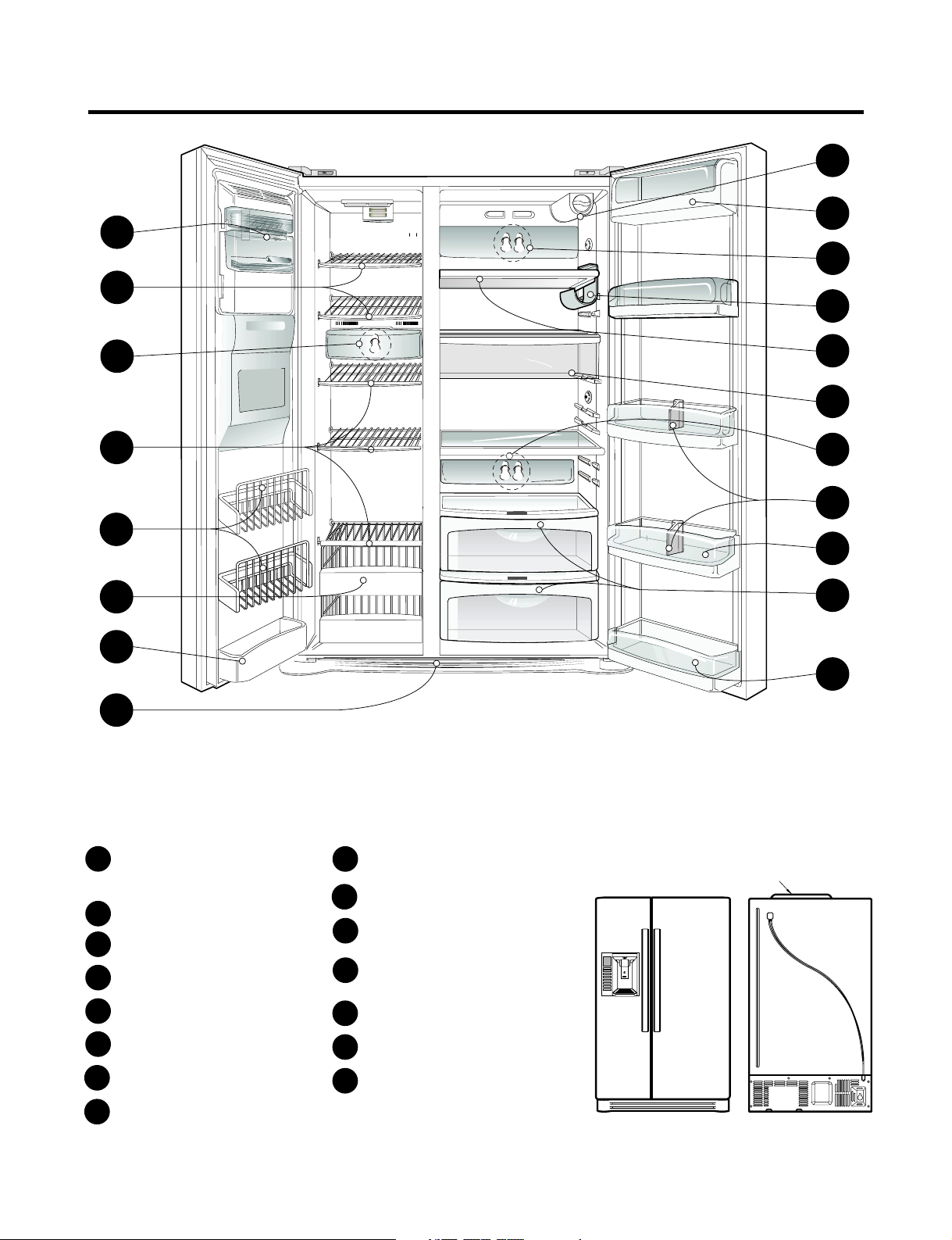
2. PARTS IDENTIFICATION
PWB Cover
PUSHPUSH
- 5 -
Use this page to become more familiar with the parts and features. Page references are included for your
convenience.
Note: This guide covers several different models.The refrigerator you have purchased may have some or
all of the items listed below. The locations of the features shown below may not match your model.
Refrigerator Door Rack
Dairy Corner
J
L
M
KRefrigerator Shelf
Freezer Door Rack
Freezer Shelf
Drawer
B
C
D
A
E
Vegetable Drawer
F
G
I
Automatic Ice Maker
For storage of dairy products
such as butter and cheese.
Freezer Lamp
Base Grille
Snack Pan
For storage of meat or fresh food.
Water Filter
H
Refrigerator Lamp
A
B
C
B
D
D
E
F
N
G
H
I
J
N
M
K
I
N
L
Bottle Guide **
** On some models
The ice is produced in the icemaker
and sent to the dispenser.
P
Wine holder **
P
3. HOW TO INSTALL REFRIGERATOR
- 6 -
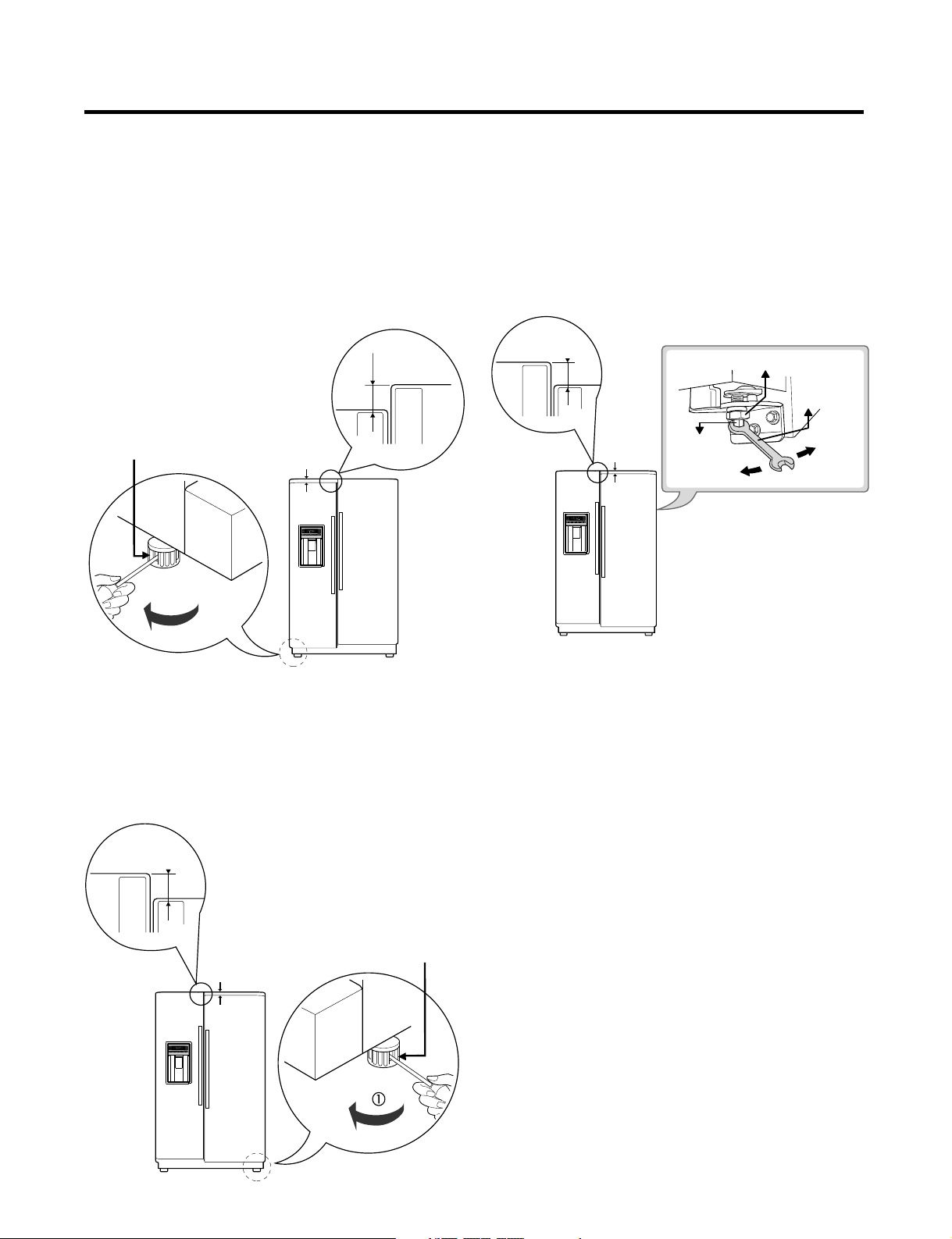
1. DOOR ALIGNMENT
Before adjust the doors, remove the Base Grille.
If the freezer compartment door is lower than
the refrigerator compartment door, make them
level by inserting flat blade screwdriver into the
groove of the left leveling leg and rotating it
clockwise.
Left leveling
leg Height
If the freezer compartment door is higher than the
refrigerator compartment door, make them level by
inserting flat blade screwdriver into the groove of
the right leveling leg and rotating it clockwise.
Left leveling leg
Height
difference
Adjust the level when the refrigerator door is lower than
the freezer door during the installation of the refrigerator.
Tools you need
• Wrench 5/16 in (8 mm)
• Wrench 3/4 in (19 mm)
AFTER LEVELING THE DOOR HEIGHT
Make sure the front leveling legs are completely
touching the floor.
difference
Height
difference
Height
difference
Height
difference
Height
difference
Using a ¾” (19 mm) wrench, turn the keeper nut clockwise
to lossen the keeper nut.
Keeper nut
Adjustment
hinge pin
Wrench
Up
Down
Using a 5/16” (8 mm) wrench, turn the adjustment hinge pin
clockwise or counterclockwise to level the refrigerator and
After setting the level door, turn the keeper nut
counterclockwise to tighten.
Do not over tightening the door adjustment screw. The
hinge pin can be pulled out. (Adjustable range of height is a
maximum of ½” (1.27 cm)).
freezer door.
- 7 -
2. WATER FILTER
It is recommended that you replace the filter when the
water filter indicator light turns on or your water
dispenser or ice maker decreases noticeably.
After changing the water filter cartridge, reset the water
filter status display and indicator light by pressing and
holding the BUTTON for 3 seconds.
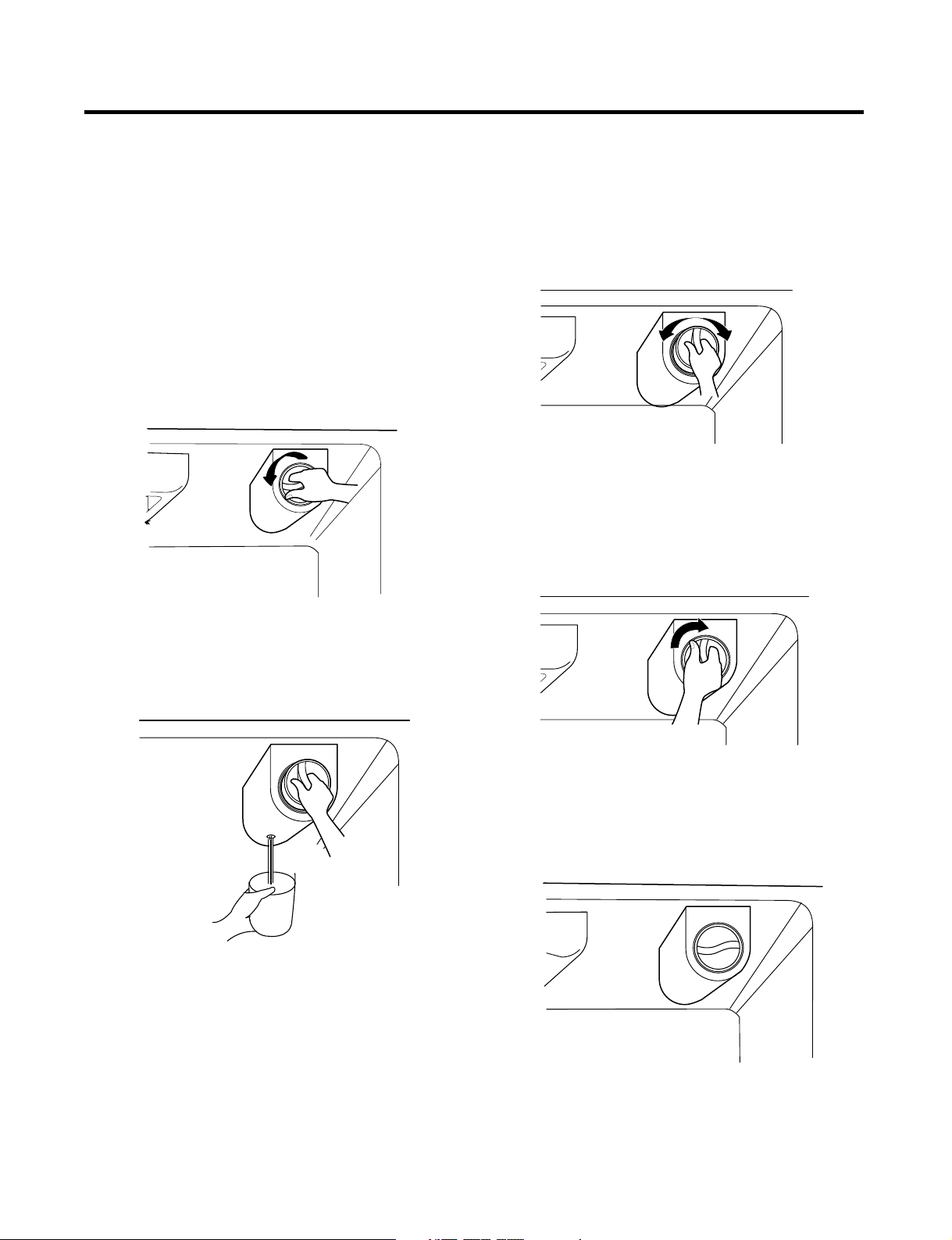
1) Remove the old cartridge.
Rotate the knob of the cartridge counter clockwise.
When the cartridge is removed, you will feel it click
out of place. Pull of the cartridge.
NOTE: Replacing filter causes small amount of water
(around 25cc) to flow out. Please put up a cup under the
hole to prevent it.
2) Replace with a new cartridge.
Take the new cartridge out of it’s packaging and
remove protective cover from the o-rings. With
cartridge knob in the vertical position, push the new
filter cartridge into the cover until it stops.
If you can turn the filter from side to side, it isn’t fully
inserted. Push it in firmly and twist it into place. You
will hear the snap when it clicks into place. Using it’s
handle, twist the cartridge clockwise about 1/4 turn.
You will hear the snap when it clicks into place.
3) Flushing the water system after replacing filter.
To clean the system dispense 2.5 gallons (9.46 L) of
water through filter before use (dispense for
approximately 5 minutes).
3-1. Confirm the amount of water supplied to the icemaker.
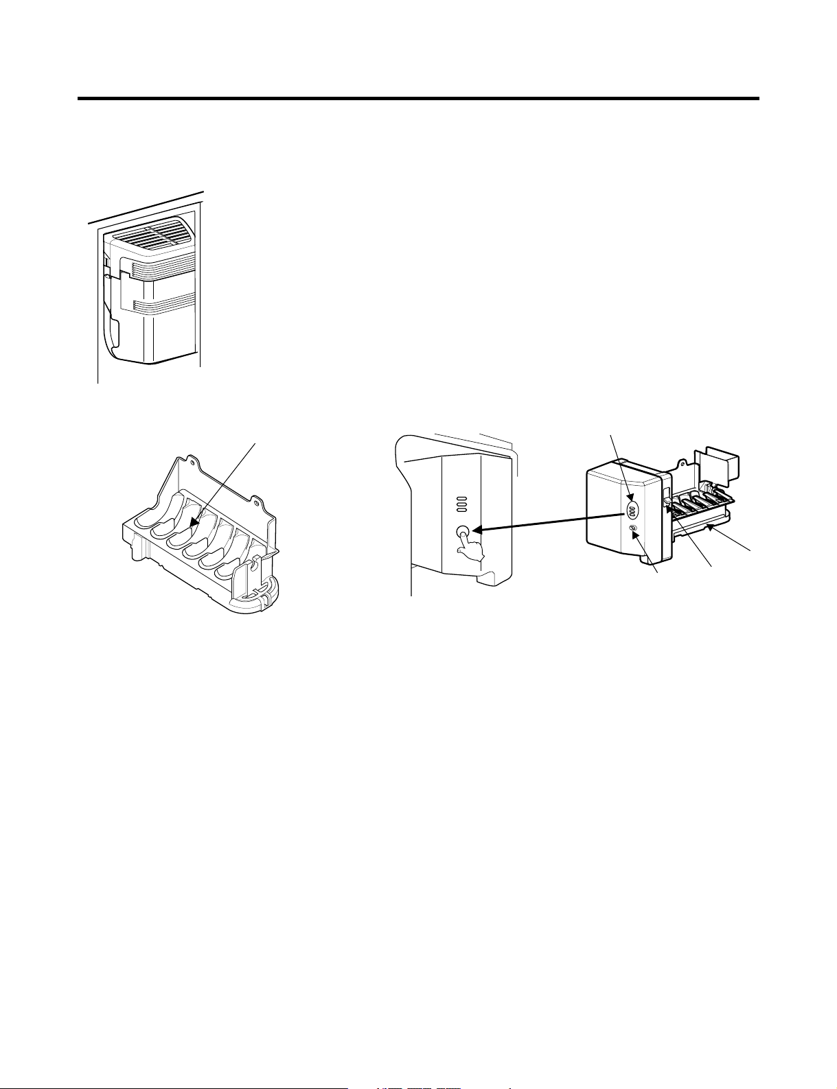
1) Confirm the amount of water supplied to the icemaker
(1) Press the button (Figure 1) to selsct the level of water (Optimum level →Large → Small.)
2) Icemaker Operation Test (Test mode)
(1) Press the button (Figure 1) for more than 3 seconds and It will start the Test mode.
(2) Test the operation of the operating part of the icemaker.
(3) If there is no problem with the operation, water is supplied through the water tube (up to the
selected lebel of water).
(4) The test mode is completed after the water is supplied.
Note : When using the test mode more than twice consecutively, water can overflow.
When the water overflows, wipe the ice storage bin.
* It is acceptable if the adjusted level of water is a bit smaller than optimum level.
Water Amount
Indicator Light
Power
Switch
Water Amount
Selection Button
Feeler
Arm
Check water level
Figure 1.
- 8 -
3. HOW TO CONTROL THE AMOUNT OF WATER SUPPLIED TO ICEMAKER
4. HOW TO DISASSEMBLE AND ASSEMBLE
1. REMOVING AND REPLACING
REFRIGERATOR DOORS
Before remove the doors, remove the Base Grille.
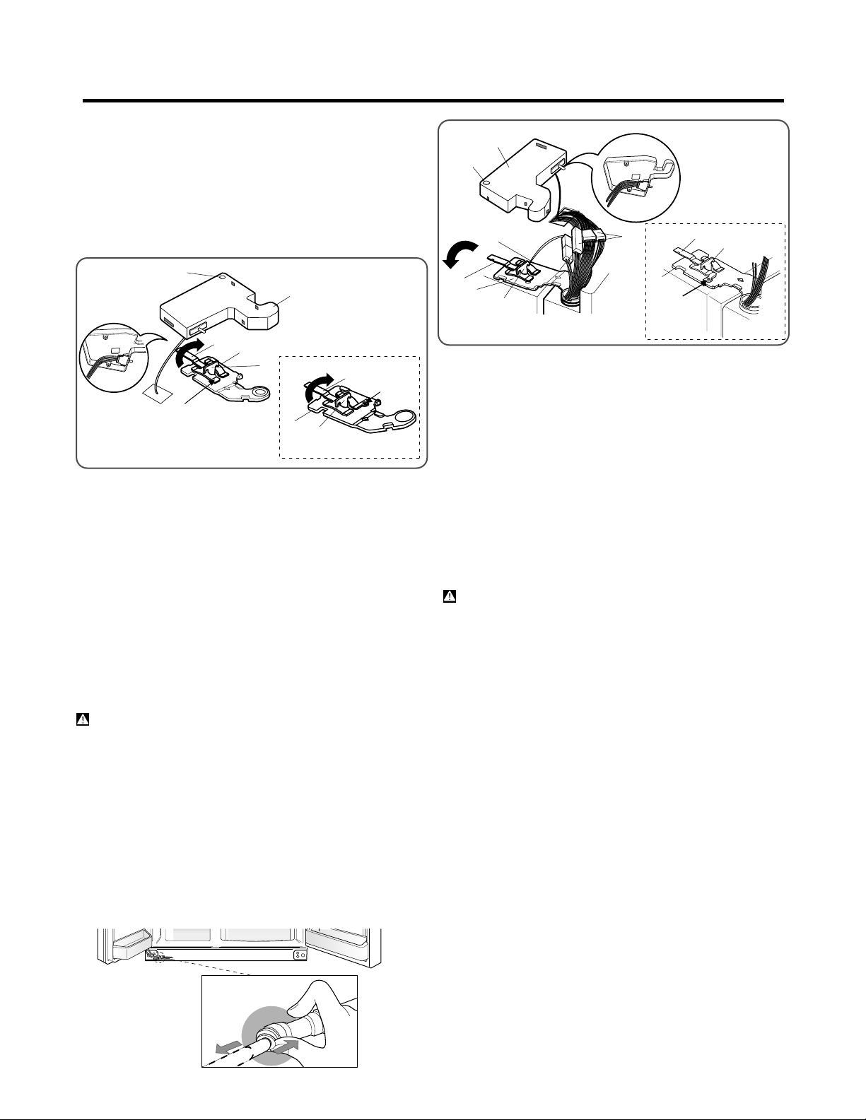
To remove the right (refrigerator) door:
CAUTION: When lifting the hinge free of the latch,
be careful that the door does not fall forward.
(1)
(2)
(3
)(4)
(5)
1. Open the door. Remove the top hinge cover screw
3. Rotate the hinge lever (3) clockwise. Lift the top hinge
2. Use a flat blade screwdriver to pry back the hooks
(not shown) on the cabinet underside of the cover (2).
Lift up the cover.
4. Lift the door from the lower hinge pin.
5. Place the door, inside facing up, on a nonscratching
surface.
(1).
Type 2
Type 1
(4) free of the hinge lever latch (5).
(3
)
(4) (5)
Rivet
NOTE: Regardless the type of hinge lever (3);
type1: without rivet or type 2: with rivet the
removal process is the same.
Removing the left (freezer) door with water line
connection.
• Pull up the water feed tube while pressing area
(Figure 1) as shown in the figure below.
If a tube end is deformed or abraded, trim the
part away. Disconnecting the tube under the door
causes about 0.5 liters water to flow out. Put a large
container at end of tube to prevent water from draining
onto the floor.
• NOTE:
Figure 1
1. Open the door. Remove the top hinge cover screw (1).
2. Use a flat blade screwdriver to pry back the hooks
(not shown) on the cabinet underside of the cover (2).
Lift up the cover.
3. Disconnect all the wire harnesses (3).
4. Remove the grounding screw (4).
5. Rotate hinge lever (5) counterclockwise. Lift the top
CAUTION: When lifting the hinge free of the latch,
be careful that the door does not fall forward.
7. Place the door, inside facing up, on a nonscratching
surface.
6. Lift the door from the lower hinge pin being careful to
pull the water lines through the lower hinge pin.
hinge (6) free of the hinge lever latch (7).
(1)
(2)
(3)
(5)
(6)
(7)
(4)
Type 2
Type 1
(6)
(5)
Rivet
NOTE: Regardless the type of hinge lever (5);
type1: without rivet or type 2: with rivet the
removal process is the same.
(7)
- 9 -

Reinstalling the rigth (Refrigerator) door
(1)
(2)
(3) (4)
(5)
Type 2
Type 1
(3
)
(4) (5)
Rivet
2. Fit top hinge (4) over hinge lever latch (5) into
place. Rotate lever (3) counterclockwise to secure
3. Hook tab on switch side of corner under edge of wire
opening in cabinet top. Position cover (2) into place.
Insert and tighten cover screw (1).
hinge.
1. Place the door onto the lower hinge pin.
NOTE: Regardless the type of hinge lever (3);
type1: without rivet or type 2: with rivet the
removal process is the same.
Reinstalling the left (Freezer) door
(1)
(2)
(3)
(5)
(6)
(7)
(4)
Type 2
Type 1
(5)
(6)
(7)
Rivet
2. Fit top hinge (6) over hinge lever latch (7) and into
place. Rotate lever (5) clockwise to secure hinge
3. Install the grounding screw (4) and connect all the
wire harnesses (3).
4. Hook tab on door switch side of cover (2) under edge
of wire opening in cabinet top. Position cover into
place. Insert and tighten cover screw (1).
1. Feed the water tubes through the lower hinge pin and
place the door onto the lower hinge pin.
5. Reconnect the water tubes by inserting the tubes into
the connectors.
NOTE: Regardless the type of hinge lever (5);
type1: without rivet or type 2: with rivet the
removal process is the same.
2. HANDLE REMOVAL
- 10 -
•
NOTE: If
Loosen the set screws with a 3/32” (2.38 mm) Allen
wrench and remove the handle.
the handle mounting fasteners need to be
tightened or moved, use a 1/4” (6.35 mm) Allen wrench.
Mounting
fasteners
Set screw
Allen Wrench
Questo manuale è adatto per i seguenti modelli
1
Indice
Altri manuali LG Frigorifero

LG
LG LFC23760 Series Manuale utente

LG
LG GRL1960TQA Manuale utente

LG
LG MFL67783510 Manuale utente

LG
LG LMWS27626SLG Manuale utente

LG
LG LRFC25750ST Manuale utente

LG
LG LMX30665 Series Manuale utente

LG
LG LFXC24796D Istruzioni operative

LG
LG GR-379TGL Manuale utente

LG
LG GP-5D906BSL Manuale utente

LG
LG LRONC1404V Manuale utente

LG
LG LTN16385PL Manuale utente

LG
LG LSXS26466 Manuale utente

LG
LG GR-559JPA Manuale utente

LG
LG LLD1331BBSL Manuale utente

LG
LG LRSC21935 Manuale utente

LG
LG GR-B352 YLC Manuale utente

LG
LG Dios GR-J303UG Series Manuale utente

LG
LG GBB59PZFZB Manuale utente

LG
LG LFX25992 series Manuale utente

LG
LG GC-309BV Manuale utente


