LG V-NET PDRYCB100 Manuale utente

P/NO : MFL67708304
www.lg.com
TYPE : Simple Dry contact
MODEL : PDRYCB100
INSTALLATION MANUAL
• Please read this installation manual completely before installing the product.
• Installation work must be performed in accordance with the national wiring
standards by authorized personnel only.
• Please retain this installation manual for future reference after reading it
thoroughly.
ENGLISH ITALIANO ESPAÑOL FRANÇAIS DEUTSCH
PORTUGUESE
РУССКИЙ ЯЗЫК

2Dry Contact
Dry Contact Unit Installation Manual
TABLE OF CONTENTS
nSafety Precautions.................................................................3
nOverview ................................................................................6
nPart Description......................................................................8
nInstallation Method .................................................................9
Installation................................................................................................9
nInstallation Guide..................................................................11
Step1......................................................................................................11
Step2......................................................................................................12
nAdministrator Guide .............................................................13

Safety Precautions
Installation Manual 3
ENGLISH
nInstallation
Service
Center
Service
Center
To prevent injury to the user or other people and property damage, the following instructions
must be followed.
nIncorrect operation due to ignoring instruction will cause harm or damage. The seriousness is
classified by the following indications.
nMeanings of symbols used in this manual are as shown below.
WARNING
CAUTION
This symbol indicates the possibility of death or serious injury.
This symbol indicates the possibility of injury or damage.
Be sure not to do.
Be sure to follow the instruction.
WARNING
Don’t touch with the hands
while the power is on.
• Cause fire, electric shock, ex-
plosion or injury.
Product installation must
be referred to a service
center or installation shop.
• Cause fire, electric shock, ex-
plosion or injury.
Request installation from
installation shop or service
center when reinstalling
the product.
• Cause fire, electric shock, ex-
plosion or injury.
Safety Precautions

Standardized
product
Safety Precautions
4Dry Contact
Do not install the product
in the place where rain can
get to the product.
• Cause product failure
Do not install the unit in
humid locations.
• Cause product failure
Do not put the product
closer to fire.
• Cause fire
Do not install in a place
that cannot withstand the
weight of the product.
• The product may get dam-
aged or may break.
Do not install the product
to a place that generates
oil, steam, salt, sulfuric
gas, etc.
• Cause the product’s deforma-
tion or failure.
Use standardized Product.
• Cause product failure
Do not change or extend
power lines arbitrarily.
• Cause fire or electric shock.
Do not give a shock to the
product.
• If you give a shock to the prod-
uct, it may cause the product’s
failure.
Do not use a heater near
the power line.
• Cause fire or electric shock.
nOperation

Service
Center
STOP
Safety Precautions
Installation Manual 5
ENGLISH
Do not spill water inside of
the product.
• Cause electric shock or
breakdown.
If the product has been in-
undated, you must refer to a
service center or installation
shop.
• It can cause a fire.
Children and elderly use the
product under the
guardian’s supervision.
• Cause accidents and product
failures.
Do not use for special pur-
pose / place such as con-
serving flora and fauna,
precision instruments, art.
• Otherwise, it can cause property
damage.
Remove the power plug
when cleaning.
• Cause fire or electric shock.
Do not place heavy objects
on the power line.
• Cause fire or electric shock.
Do not disassemble, repair,
or modify the product.
• Cause fire or electric shock.
Do not touch with wet
hands.
• Cause fire or electric shock.

6Dry Contact
Overview
LG Dry Contact is a solution for automatic control of air conditioning system at the owner’s behest.
In simple words, it’s a switch which can be used to turn the unit On/Off after getting the signal from external
sources like key-in lock, door or window switch etc specially used in Hotel rooms.
It’s a small PCB that either can be fit inside the control box of Indoor unit or can be outside the unit in a plastic case
if there is no sufficient space inside the Indoor unit.
Apart from simple installation, it can also be linked to Central Controller via Indoor unit PI485 pcb. For this, all con-
necting wires & an additional small pcb for looping is also provided along with Dry Contact.
Dry Contact can be used in two ways.
1. It can be used to actually turn On/Off the system on receiving the signal from the source.
In this case, user doesn't need to use remote controller anymore to turn On/Off the system.
However all the further settings like temperature, fan speed, mode etc can be done through remote controller
only.
2. Other way is almost similar as above but in this case, after getting the On signal from the external source, user
has to turn On the system from remote controller only. Dry contact just activates the system.
However system can be turned Off directly from the external source. So only On mode is different here.
So in both of above conditions, system can’t be operated without signal from external source which prevents un-
necessary use of system & facilitates its operation only when its required.
These settings can be selected from the remote controller whose details have been explained in the later part of
this manual
So depending upon the requirement, Dry Contact offers a variety of applications to suit the customer’s requirement
in the best possible way.
Overview

Installation Manual 7
ENGLISH
Overview
Indoor PCB
Connector
Power Connector
Dry Contact Controller
Connector

8Dry Contact
Part Description
PDRYCB100 (PCB + Case)
CN-POWER : 24 V~ Connector
CN-CC : Indoor PCB Connector
CN_DRY(L): DRY CONTROLLER Connector
CN_DRY(SIG): DRY CONTROLLER Connector
CN_DRY(ERROR CHECK): ERROR Check Display Connector
CN_DRY(OPER STATE): Operation Display Connector
1
2
3 4 5 6
PCB
Front Case Rear Case
Side Side
ISO View
Cable(1 EA)
(For Connecting with indoor unit)
Installation Manual
Cable 1 EA
(For Central Controller)
Connecting PCB:
6871A30056A
1
2
3
4
5
6
Part Description
* Others :
Screw 4 EA(For installation)
Clamp 4 EA(For installation)
Installation Manual 9
ENGLISH
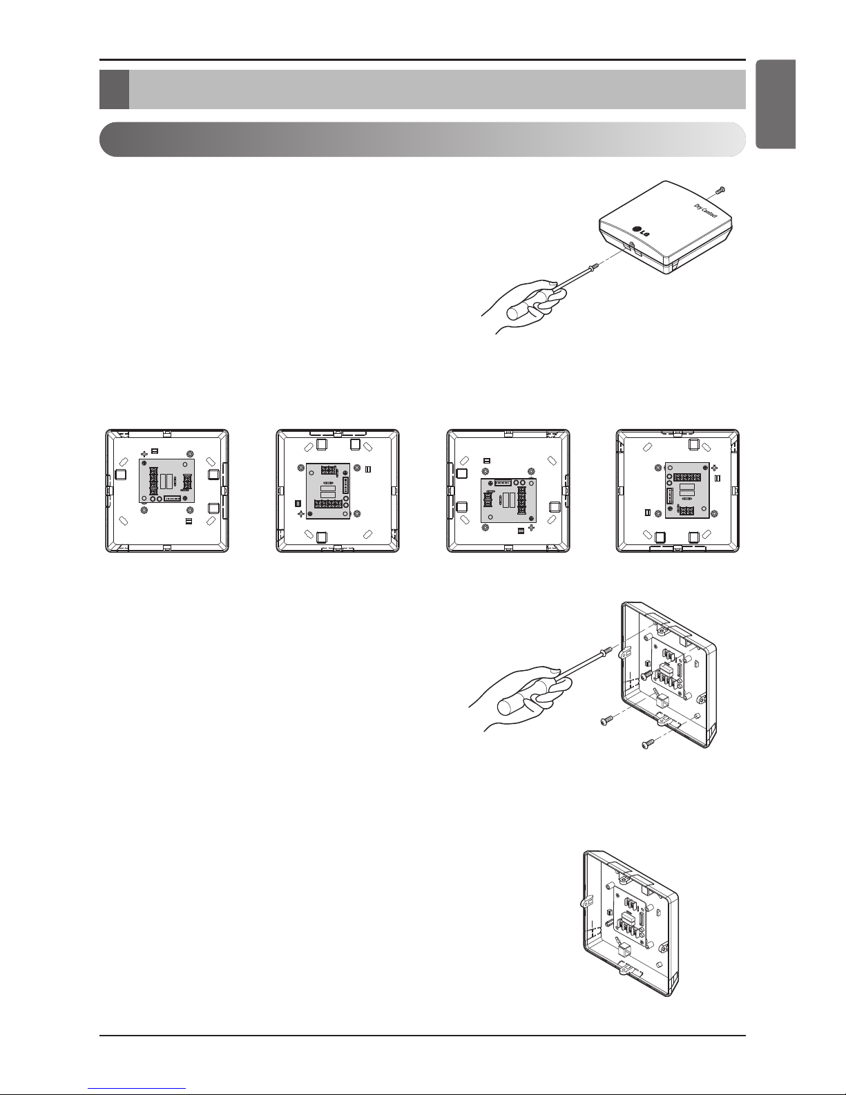
Installation Method
Installation
1) Loosen and remove two screws that secure the prod-
uct.
2) Position the rear case to the direction towards to the
connector for convenient cable arrangement.
3) Secure the rear case on the installation place using the
supplied fixing screws.
4) Remove knock out shapes on the rear case (4-sided)
according to the connector’s size and direction.
Installation Method

10 Dry Contact
Installation Method
5) Connect the connection wires properly according to the connection method. (Refer to the instruction
and set-up description)
6) Set the switch according to the setting method. (Refer to the instruction and set-up description)
7) Tighten the fixing screws on the top and bottom of the case.
1. Install the product on flat surface and install anchoring screws at more than 2 places. Otherwise
the central controller may not be anchored properly.
2. Do not tighten anchoring screws too tightly. It may cause deformation of the case.
3. Do not deform the case at random. It may cause malfunction of the central controller.
Altri manuali per V-NET PDRYCB100
1
Indice
Lingue:
Altri manuali LG Interruttore


