Lightwave JSJSLW920 Manuale utente
Professional Series
www.lightwaverf.com
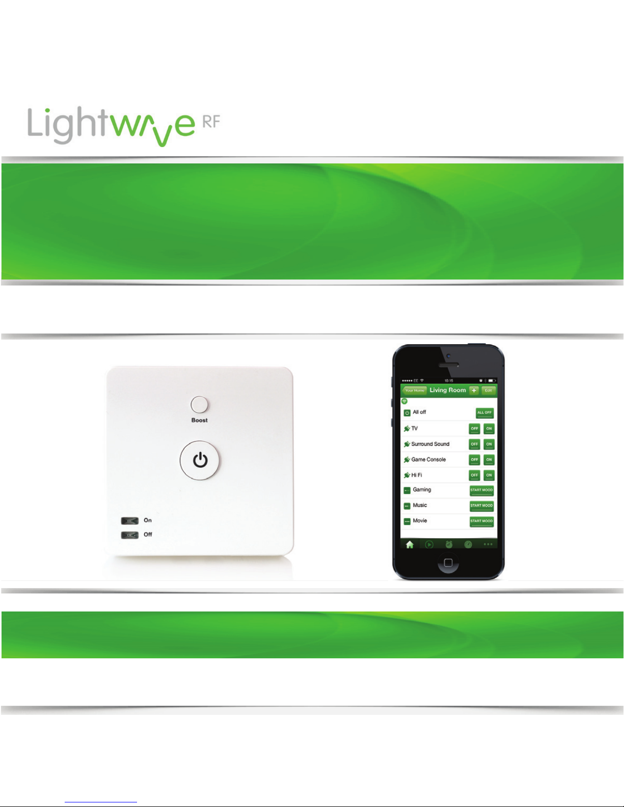
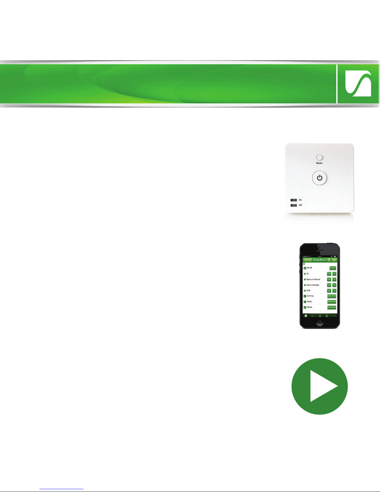
Boiler Switch
Model No. JSJSLW920
Instruction Manual

EC DECLARATION OF CONFORMITY
Responsible Authority:
LightwaveRF PLC,
Innovation Campus Birmingham
Faraday Wharf
Holt Street
Birmingham
B7 4BB
Tel: +44 (0)121 250 3625
Model Number(s): JSJSLW920
Description: Boiler Switch
Directives this equipment
Complies with: 2006/95/EC The Low Voltage Directive N/A
2004/108/EEC The Electromagnetic Compatibility Directive
1999/5/EC R&TTE Directive
93/68/EEC CE Marking Directive
Standards Applied in order to verify compliance
Safety: BS EN 60730-1: 2011
Health:
R&TTE: EN 301 489-1 V1.9.2: (2011-09), EN 301 489-3 V1.4.1: (2002-08)
EN 300 220-1 V2.1.1: 2006, EN 300 220-2 V2.1.2: 2007
EMC: EN 301 489-1 V1.9.2: (2011-09), EN 301 489-3 V1.4.1: (2002-08),
EN 55022: 2010, EN 61000-3-2: 2006 +A1: 2009 +A2: 2009 Class A,
EN 61000-3-3: 2008, EN61000-4-2: 2009,
EN 61000-4-3: 2006 +A1: 2008 +A2: 2010, EN 61000-4-4: 2012,
EN 61000-4-5: 2006, EN 61000-4-6: 2009, EN 61000-4-11: 2004
For and on behalf of LightwaveRF PLC
----------------------------------------
Name J Shermer
Position Managing Director
What do I need?
How do I get started?
To install the Boiler switch, please follow these
instructions. You must also refer to the wiring
instructions specific to your boiler type which can
be easily downloaded at
www.lightwaverf.com/product-manuals or by
scanning the QR code below. The setup guide in
these instructions will then explain how to link the
Boiler Switch to the LightwaveRF Home
To install the Boiler Switch, you must understand
how to safely turn o the electricity supply and
be comfortable with following some basic wiring
instructions. You will also need suitable electrical
screwdrivers.
Get started
Help Video & further guidance
For additional guidance, and to watch a video
that will help guide you through the installation
process, please visit the support section on
www.lightwaverf.com
IMPORTANT: All LightwaveRF products can be legally DIY installed in your
own home; however, if in doubt, always consult a qualified electrician or
heating engineer. It is important to install this product in accordance with
the following instructions. Failure to do so may void your warranty.
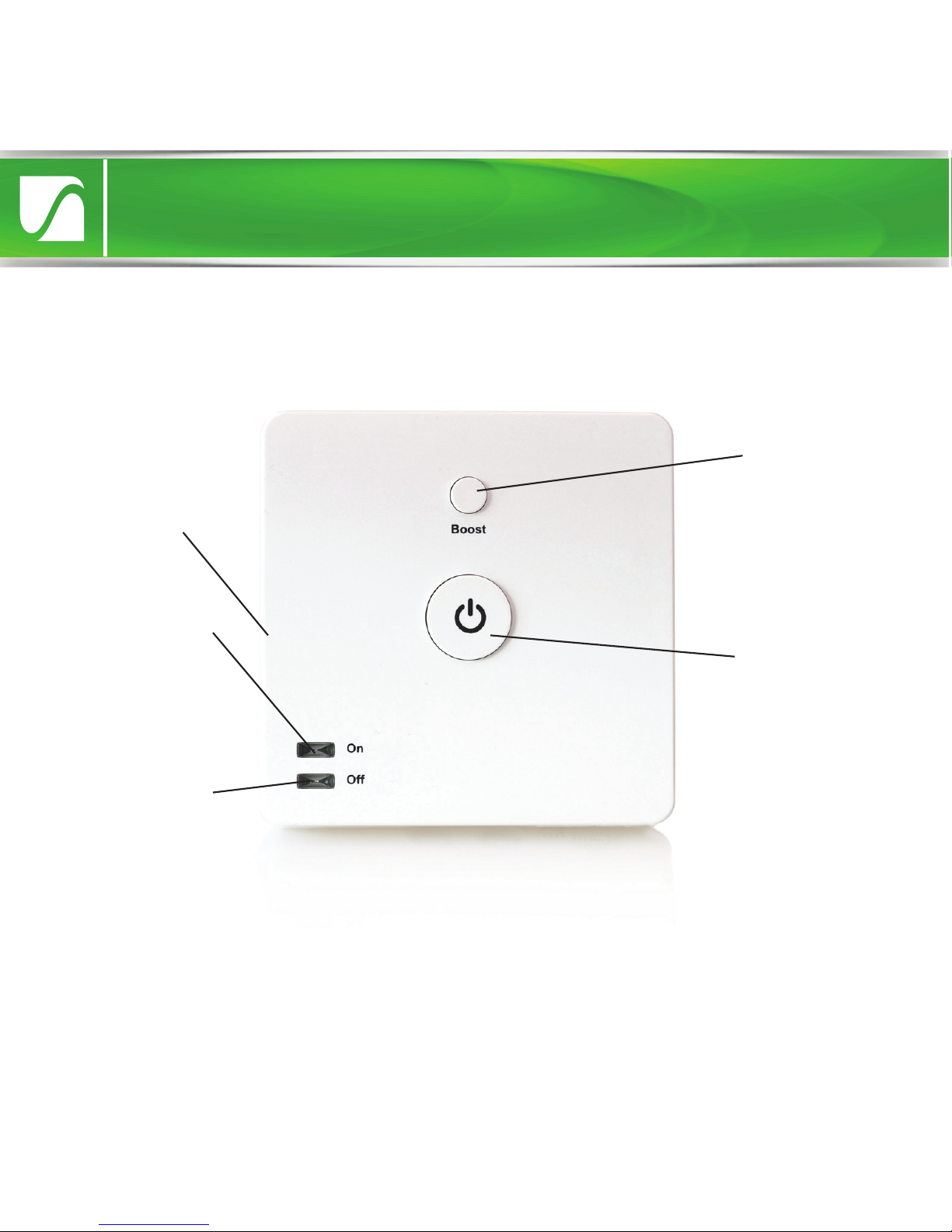
‘O’ LED. When
illuminated
boiler is o.
Boost button.
Temporarily
turns on boiler.
‘On’ LED. When
illuminated
boiler is on.
Overview
Standby button.
Turns boiler
on/o
Linking button.
Press to enter
linking mode
Quick Start Guide
Installation
Front view
Hook
Cable clamp
mount (clamp
removed)
Backplate
screw hole
Cable hole
(cover not
removed)
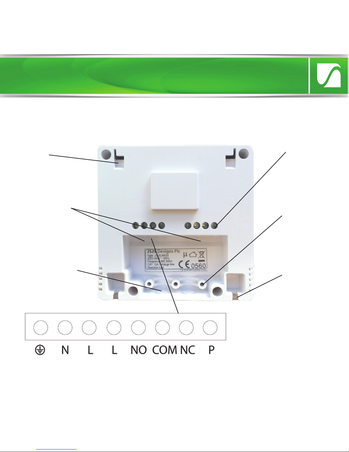
Wiring
terminals
Tightening
Screws
Installation
Rear view with backplate removed
IMPORTANT: If conducting an insulation resistance test, all LightwaveRF
products must be disconnected from the mains, or damage will occur.
Close-up of
wiring terminals
Quick Start Guide
Installation
Installation preparation
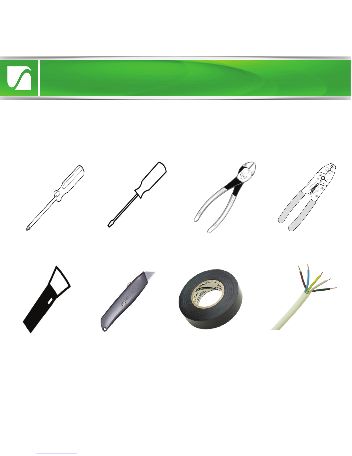
Key installation tools and materials
IMPORTANT: If you are unsure about how to use any of these tools and
materials, or any stage of the installation process, always consult a qualified
electrician or heating engineer.
Cross-head
screwdriver
Flat-head
screwdriver Wire-cutters Wire-strippers
Torch Electrical tape 5 core cable
Sharp Knife

Safety Precautions
Installation
•
Prior to installing the Boiler Switch, read through the wiring instructions
provided thoroughly. Make sure that you understand your heating setup as
specified on the following pages.
•
Before proceeding with the installation, check and ensure that the boiler
is OFF and that no mains power is being received. Remember - the mains
terminals remain live even if the boiler’s on/o controls are switched o. If
a separate wiring centre needs to be accessed, make sure that no power is
being received. If in doubt always consult a qualified electrician.
•
Ensure that the Boiler is earthed.
•
Never take unnecessary risks if unsure, as damage can be caused by an
incorrect installation.
•
Do not strip the outer sheathing of flexible cables more than necessary to
prevent short circuits.
•
Ensure that all cords pass through the cable clamps in the rear of the
control box and are securely fixed. Ensure that the power supply is
connected such that the current carrying conductors become taut before
the earth conductor should the supply cord slip from the cable clamp.
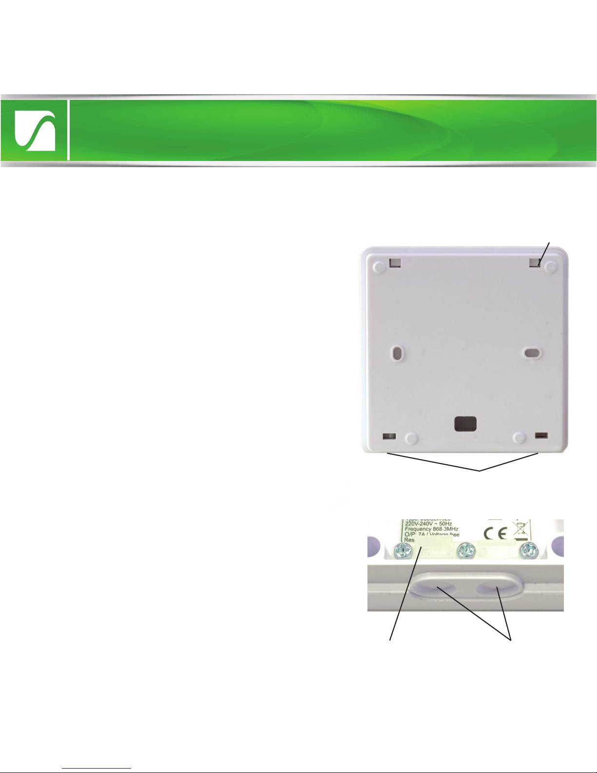
Remove the backplate and cable clamp
To gain access to the wiring terminals on
the Boiler Switch, you must first remove
the backplate. This can be done by
loosening the two screws sited at the
base of the unit using a suitable
screwdriver. Once the screws are
loosened enough so that they protrude
from their screw holes, gently lift the
backplate away from the main unit and
slide it down. Once the hooks are free
from their mountings, the backplate
should slide free. Screws
Installation
Hook
Once the backplate has been removed, the
cable clamp needs to be unscrewed ready
to accommodate the wires. There are also
two capped holes situated at the base of
the unit. One of these (or two depending
on the number of cables used) needs to
have its cap removed using a suitable
blade so that the wires can pass through.
Holes
Clamp

To know where to install the Boiler Switch, you will need to know the type of
heating setup that you have at home. Please identify your system and then
refer to the corresponding section after this page.
1. Combi boiler (most common) - In the vast majority of cases, your domestic
boiler will be a standard ‘combi’. It provides both hot water and water for
central heating directly. It may have an accompanying ‘room thermostat’
which is usually located in the hall.
2. Y plan system - this consists of a ‘system’ boiler which supplies both a hot
water tank and the central heating. There is a single motorised valve which
distributes heated water to either the hot water tank, the heating or both. It
will usually include a room thermostat.
3. S plan system - this also consists of a system boiler supplying both a hot
water tank and the central heating. In this case there are two motorised valves,
one regulating the supply for the hot water and one for the heating. It will
usually include a room thermostat.
4. Multi-zone system (S plan plus) - this is similar to the S plan system, but has
multiple motorised valves controlling supply to dierent heating areas or ‘zones’.
Understanding your heating setup
Installation

The setup show below is a standard combi system which is common to most
homes. Combi systems may or may not include a ‘room thermostat’ such as
the one pictured. This is wired into the room thermostat terminal. Even if
there is no existing room thermostat, a combi boiler will always include a
room thermostat (RT) terminal into which a thermostat can be wired. This is
where the LightwaveRF Boiler Switch should be connected (see next page).
Optional ‘room thermostat’
(usually located in the hallway)
Wired connection
Standard
‘combi’ boiler
The thermostat is wired into the ‘room thermostat’ (RT)
terminal in boiler (standard terminal in all combi boilers)
1. Wiring to a standard combi setup (typical)
Quick Start Guide
Install 1: combi boiler
Indice
Altri manuali Lightwave Interruttore


