Lippert HAPPIJAC Manuale utente

HappiJac® Bed Lift
OWNER'S MANUAL

Rev: 06.30.22 Page 2 CCD-0001575
TABLE OF CONTENTS
Introduction 2
Safety 3
Product Component Descriptions 4
Frame 4
Brackets 5
Limit Switches 5
Bunk Stop Settings 6
Operating Precautions 6
Operation 7
Control Switch 7
Upper Trolleys 7
Automatic Upper Bunk Lock-Up System Option 8
Lower Trolley: Sofa or Dinette Conguration 9
Adjustments 10
Timing 10
Upper Trolley Tab Rotation 11
Lower Trolley Sofa/Dinette Bracket Removal 12
Lower Bunk Trolley Tab Installation 13
Maintenance 14
Troubleshooting 14
Emergency Manual Operation 15
Manually Raise the Bed(s)/Sofa or Dinettes 15
Manually Lowering the Bed(s) 16
Notes 17
Introduction
The HappiJac® Bed Lift System is a chain-driven two trolley lift system operated by a 12V DC motor, which
can be installed in most toy hauler trailers. It can accomodate one or two beds, or an alternate of a bed and a
dinette/sofa configuration.
Voltage = 12V DC
Nominal Current Draw = 8 amps (1 bed going up)
12 amps (2 beds or 1 bed and 1 sofa/dinette configuration going up)
Load Limit = 450 pounds dynamic (moving) load
600 pounds static (stationary) load
NOTE: These ratings are for the lifting mechanism only. HappiJac does not manufacture and therefore does
not rate any attachments, such as bed platforms, sofas, etc. Load ratings for these items would be
the responsibility of the manufacturer.
This product is designed and intended to be used only as a bed lift mechanism. Any other use of this system
will void any and all written or expressed warranties.
Additional information about this product can be obtained from lci1.com/support or by downloading the
free LippertNOW app. The app is available on Apple App Store® for iPhone® and iPad® and also on Google
Play™ for Android™ users.
Apple App Store®, iPhone®, and iPad® are registered trademarks of Apple Inc.
Google Play™ and Android™ are trademarks of Google Inc.
For information on the assembly or individual components of this product, please visit:
https://support.lci1.com/beds-support-happijac-beds

Rev: 06.30.22 Page 3 CCD-0001575
The "WARNING" symbol above is a sign that a procedure has a safety risk involved and may cause death
or serious personal injury if not performed safely and within the parameters set forth in this manual.
Failure to follow instructions provided in this manual may result in death, serious personal injury
and/or severe product and property damage, including voiding of the component warranty.
Safety
This manual provides general instructions. Many variables can change the circumstances of the instructions,
i.e., the degree of difficulty, operation and ability of the individual performing the instructions. This
manual cannot begin to plot out instructions for every possibility, but provides the general instructions,
as necessary, for effectively interfacing with the device, product or system. Failure to correctly follow the
provided instructions may result in death, serious personal injury, severe product and/or property damage,
including voiding of the Lippert limited warranty.
Always wear eye protection when performing service, maintenance procedures. Other safety
equipment to consider would be hearing protection, gloves and possibly a full face shield,
depending on the nature of the task.
Moving parts can pinch, crush or cut. Keep clear and use caution.
The "CAUTION" symbol above is a sign that a procedure has a safety risk involved that may cause
personal injury and/or product damage, including voiding of warranty, if not performed safely and
in accordance with the safety procedures stated herein.

Rev: 06.30.22 Page 4 CCD-0001575
Product Component Descriptions
Frame
The lift system frame has four vertical c-channel rails (Fig. 1A). Each c-channel rail encases a chain drive and
trolleys (Fig. 2) with attached brackets that travel between upper and lower limit switches.
Fig. 1
Fig. 2
Upper Trolley
A
Standard
Lower Trolley
Slotted
Lower Trolley
NOTE: The HappiJac bedlift may come
equipped with either the standard
lower trolley or the slotted lower trolley.

Rev: 06.30.22 Page 5 CCD-0001575
Fig. 4
Fig. 3
Brackets
The lift system comes installed with screw-in tab brackets (Fig. 3) affixed to the upper trolleys and/or the
lower trolleys. The slotted lower trolleys can be fitted with hooked tab brackets (Fig. 4) for a lower bed
platform, or hooked brackets with movable arms (Fig. 5) that can accommodate a sofa/dinette configuration.
Fig. 6
Limit Switches
Upper and lower limit switches (Fig. 6A) are located behind the C-channel and secured by two small screws
(Fig. 6B). The limit switches are used to stop the bed(s) at their maximum travel range. However, the lower
bed platform can be stopped and used at any desired height. After the control switch is released, the electric
brake is set — securing the bed(s) in the current position.
B
A
Fig. 5
For the sofa/dinette configuration, sofas should be run to the lower limit switch stop and the sofa support legs
extended before using the sofas.
NEVER sit on or use sofas without sofa support legs extended. Failure to do so may result in personal
injury and/or damage to the bed lift mechanism.
Sofa support legs should not contact the oor prior to the bed lift reaching its lower travel limit.

Rev: 06.30.22 Page 6 CCD-0001575
Bunk Stop Settings
The upper bunk trolley is free-floating and is carried by the lower trolley. The height at which this trolley
stops is set by "stop blocks" which sit inside the trolley rails. To change this stop, remove the two screws
holding the bed in place, and move it to the desired height (Fig. 7). Repeat for all four corners.
Fig. 7
Stop
Block
Operating Precautions
• ALWAYS raise the bed(s) to the full up position when the trailer is being towed to avoid damage to the bed
lift system as a result of bouncing.
• ALWAYS make sure that the areas above, below and adjacent to the bed(s) are free from obstructions
before operating the bed(s).
• ALWAYS check before operating bed(s) to ensure that there is nothing interfering with the travel of the
chain mechanism inside the c-channel.
• ALWAYS use care when loading cargo/vehicles in the bed area. This is to avoid damage to the bed
mechanism.
• ALWAYS properly secure loads in the bed area to avoid damage to the bed mechanism from shifting or
falling loads.
• NEVER operate the bed(s) with any items other than bedding on the bed platform(s).
• NEVER travel with any items other than bedding on the bed(s). Loose items can become projectiles.
• NEVER operate the bed(s) when persons or pets are on the bed platform.
• NEVER hang from, or hang more than 20 pounds, on the cross-connecting shaft.

Rev: 06.30.22 Page 7 CCD-0001575
A
B
Fig. 9
Operation
Control Switch
NOTE: Upper and lower trolleys move together, unless bunk platform trolleys are stowed.
The upper and lower trolleys are operated from the control switch (Fig 8). Pressing and holding the switch in
the UP position (Fig. 8A) moves the trolleys upward. Pressing and holding the switch in the DOWN position
(Fig. 8B) moves the trolleys downward.
Upper Trolleys
The upper trolleys are only used to support a bed platform. Bed platform rails (Fig. 9A) are secured to the tab
brackets (Fig 9B) and the bed platform rests on the platform rails.
Fig. 8
A
B
NOTE: Bed platform has
been removed
for clarity.
The upper trolleys can be locked into place with bunk pins (Fig.9C) or the Automatic Bunk Lock-up System
Option on the next page.
To stow with bunk pins:
1. Run the beds up to the FULL UP stop.
2. Insert the locking pins through the trolley rails.
3. Lower the bottom bunk to the desired height.
To un-stow with bunk pins:
1. Run the beds up to the FULL UP stop.
2. Remove the locking pins from the trolley rails.
3. Lower both bunks until top bunk rests on the bunk stop and the lower bunk is at the desired height.
C

Rev: 06.30.22 Page 8 CCD-0001575
Automatic Upper Bunk Lock-Up System Option
Each of the lower trolleys has a lock-up mechanism attached. This mechanism pushes the upper bunk
trolleys into spring-backed bunk lock assembly (Fig. 10A) bolted into the C-channels. This prevents the
upper trolleys from lowering when the lower trolleys are lowered.
Fig. 11
A
Locking the Upper Bunk Trolleys
1. If the lower trolleys have a sofa or dinette attached, rotate the seatback(s) to the horizontal position.
2. Flip the locking mechanism tab (Fig. 11A) so the long portion of the tab is outside of the C-channel.
Repeat for the other locking mechanisms.
A
Fig. 10
3. Press UP on the control switch until the upper bunk is in the full up position where the bed lift shuts off
automatically. This will push the upper trolleys into the locking brackets.
NOTE: There is an audible click when the locking mechanism engages. If the mechanism fails to latch up,
check to make sure the bunk lock assembly bolt is not too tight and that the bunk lock assembly
mechanism springs back freely within the C-channel..
4. Press DOWN on the control switch to lower the lower trolleys and make sure that the upper bunk
trolleys are locked into place.
NOTE: If one or more of the trolleys is not locked into place, check all alignments and component
installations. See Timing in Adjustments for checking and correcting alignment.

Rev: 06.30.22 Page 9 CCD-0001575
A
Fig. 13
Releasing the Upper Bunk Trolleys
1. Flip the locking mechanism tab (Fig. 12A) to the release position, where the long portion of the tab is
inside the C-channel. Repeat for the other locking mechanisms.
2. Press the UP switch until the lower trolley disengages the upper bunk from the locking mechanism.
3. Press the DOWN switch to bring down the upper bunk trolleys along with the lower trolleys.
A
B
Fig. 12
Lower Trolley: Sofa or Dinette Configuration
The lift system can be configured to accommodate a bed on the upper trolley and a sofa or dinette on the
lower trolleys. The sofa or dinette will need extra brackets that will lock into the lower trolleys.
NOTE: Bracket shown without sofa or dinette attached. Consult the manufacturer's instructions for bracket
installation on sofa or dinette units.
Lowering the Arm
1. Remove the lockpins securing both bracket arms (Fig. 13A).
2. Pull up slightly on the bracket arm (sofa or dinette seat base) (Fig. 13B), then pull out.
3. Gently lower the arm (sofa or dinette seat base).
4. Re-insert lockpins.
Rev: 06.30.22 Page 10 CCD-0001575
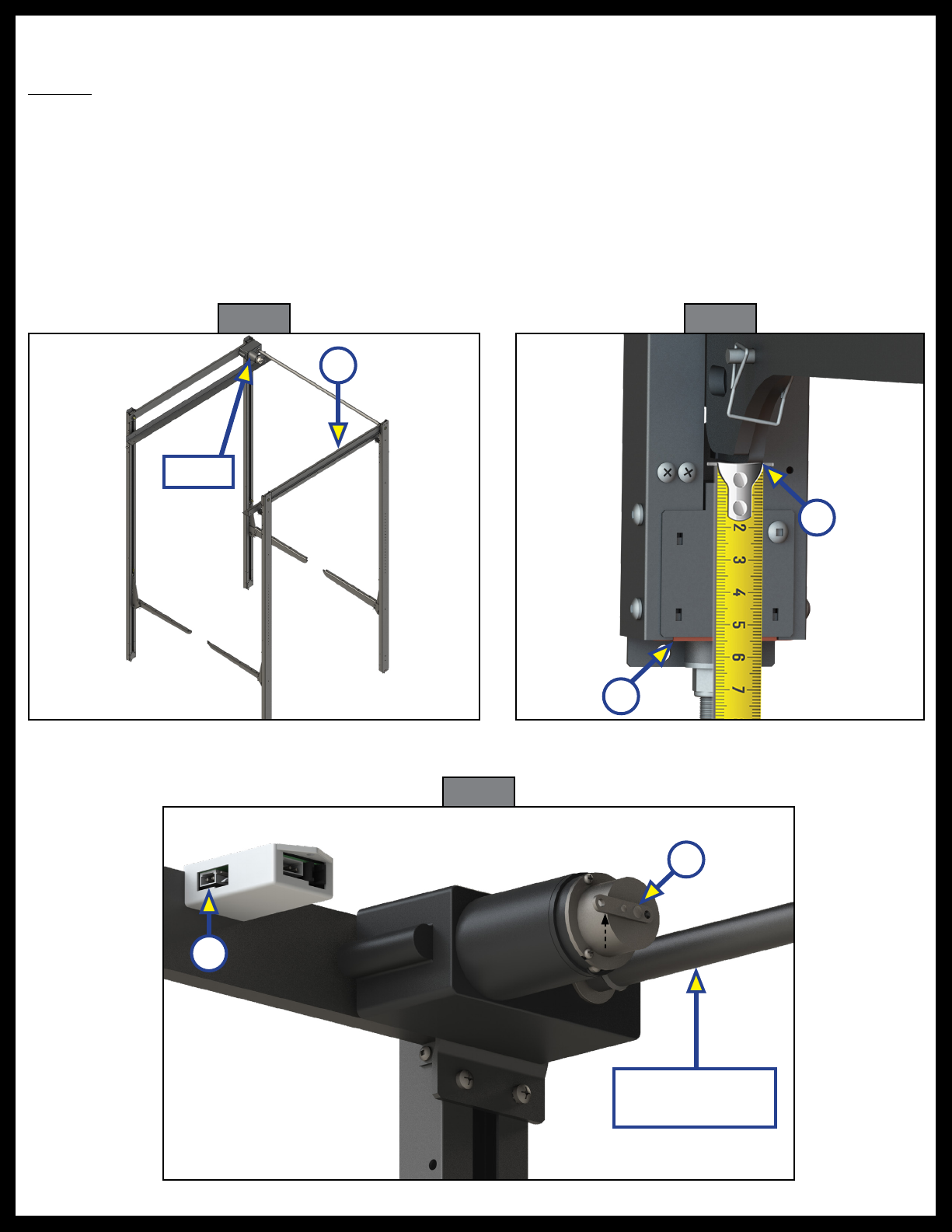
Fig. 14
Adjustments
Timing
Resources Required
• Tape measure
• ½" Socket wrench
To make sure all four corners of the HappiJac Bedlift latch and unlatch properly, the non-motor side (Fig.
14A) of the bedlift system should be set ¼" to ½" higher than the motor side. To adjust the timing:
1. Press the DOWN switch to lower the bedlift system until it stops.
2. Measure from the bottom of the lower trolley sofa bracket (Fig. 15A) to the bottom of the C-channel (Fig. 15B).
Fig. 15
B
A
A
A
3. Unplug the motor from the relay control module (Fig. 16A).
4. Release the brake by moving the release level to the "OFF" position (Fig 16B).
Fig. 16
Motor
Cross-connecting
Shaft
B
Indice
Altri manuali Lippert Sistema di sollevamento


Manuali Sistema di sollevamento popolari di altre marche


Genie
Genie Z-60/34 Manuale utente

Screen Technics
Screen Technics INTERFIT Vertical Up Lift Manuale utente

Mortuary Lift
Mortuary Lift ULTIMATE 1000 Manuale utente

Custom Equipment
Custom Equipment Hy-Brid 3 Series Manuale di programmazione

Custom Equipment
Custom Equipment Hy-Brid Lifts 2 Series Manuale di programmazione

Hy-Brid Lifts
Hy-Brid Lifts HB-P3.6 Manuale di programmazione


