
MAGNOVENT ECOBLADES Manuale utente
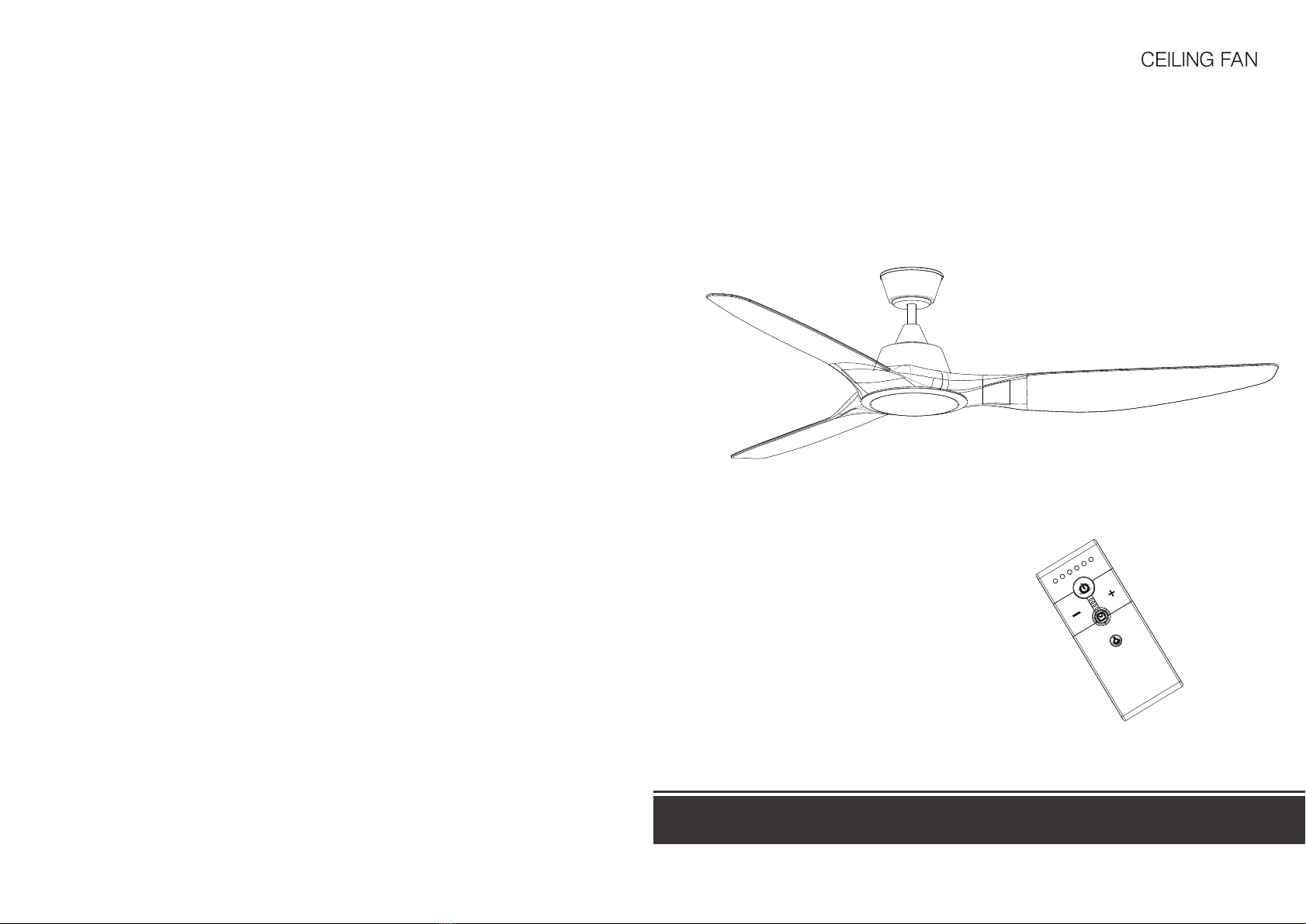
OPERATING INSTRUCTIONS
1. Safty precautions
Table of Content
1. Safety precautions--------------------------------------------------------------2
2. Parts & Accessories------------------------------------------------------------2
3. Fix hanger bracket--------------------------------------------------------------3
4. Take out the upper housing----------------------------------------------------4
5. Blade assembly----------------------------------------------------------------4
6. Upper housing assembly -------------------------------------------------------5
7. Downrod canopy & coupling cover installation--------------------------------5
9. Power supply wire connection-------------------------------------------------6
10. Fan mounting-----------------------------------------------------------------7
11. Remote controller operation--------------------------------------------------8
Uninsulated "Dangerous high voltage" inside the device. To avoid
electrical shock, non-professional personnel are forbidden to open
the housing.
Security components and parts must be replaced according to the
original demand with this sign in the machine. There is no any
serviceable parts for non-professional personnel inside the device.
Please commission qualified personnel to overhaul.
WARNING !
WARNING
Warning: Risk of electrical shock, do not open.
Against electrical shock warning: There is no any serviceable parts for non-professional
personnel insidethe device. Please commission qualified personnel to overhaul.
High voltage dangerous, non-professional
personnel are forbidden to open the housing.
Warning
This product is designed to use only those parts supplied with this product
and / or accessories designated specifically for use with this product. Using
patrs and / or accessories not designated for use with this product could
result in personal injury or property damage.
Installation must be carried out by a qualified installer, users are
forbidden to install.
1. Turn off the power before the assembly and disassembly. To avoid electrical
shock, assembly must be operaed accounding to the order from ground lead,
pull line to power line, disassembly from power line, null line to ground lead.
2. Ensure that all screws have to be locked in the course of installation.
3. Fan running, nothing can touch blades in avoiding risks.
4. The appliance must be permanently connected to the electricity supply
through a double plle switch having a contact separation of at lease 3mm
in all poles.
5. Do not connect ceiling fan to any dimmer switch or regulator.
6. The ceiling fan must be mounted at a min, height of 8.2 feet / 2.5m of
clearance from the floor and 3 feet / 1m from the wall to the blade.
7. Do not install at areas / place near / at
a) chemicals and alkali
b) flammable area such as gas cooker
c) oily places
d) wet and high humidity area such as shower room
e) high vibration / impact and continuously expose to direct wind
8. Do not place any objects in the path of the blades.
9. When all electrical connections are done, store all wires neatly.
10. Make sure that screws and connection are tighten till snug.
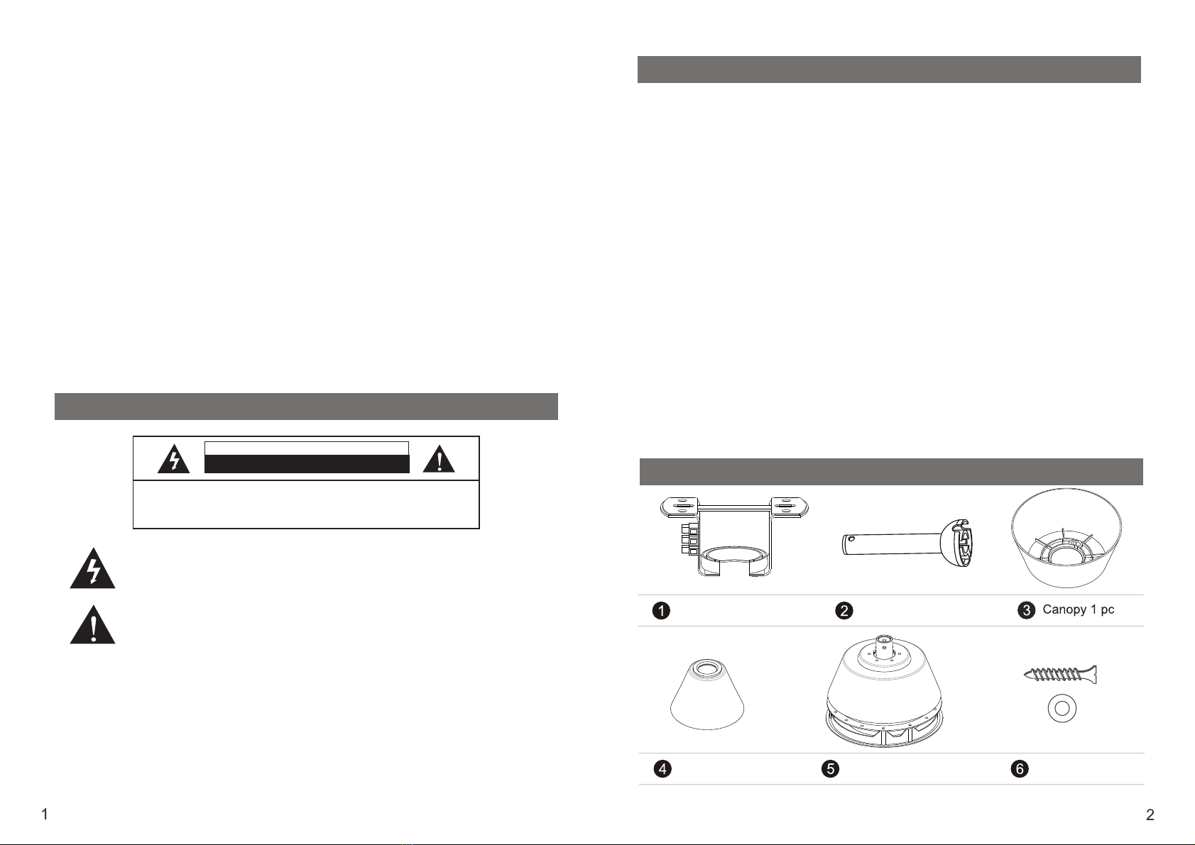
2. Parts & Accessories
Hanger Bracket 1pc
Coupling Cover 1pc Motor Assembly 1pc Wood Screw 4pcs,
Washer 4pcs
12. Information for licensed electrician and fan owners------------------------10
13. Important facts---------------------------------------------------------------------------11
Downrod 1pc
8. Light cover assembly-------------------------------------------------------------------6

4. Take out the upper housing
10 Blade 3pcs
9Light Cover 1pc
Expansion Screw 2pcs Remote Control 1 set
Note: If there is no shortage, you can install now.
1) Wooden ceiling, fix the hanger
bracket by boring the beam with
wood screws.
2) Concrete ceiling, according to
the length if expansion screws,
bore holesby precussive drills
with Φ8mm drill. After that , fix
the hanger bracket onceiling by
expansion screws.
Fix the hanger bracket by different screws base on the material of ceiling.
Do not fix the hanger bracket in ceiling which thinner than 10mm directly
in avoiding risk of wood screw loosen. After fixing the hanger bracket,
ensure that can carry more than 68Kgs (pull it by hands) for safty.
3. Fix hanger bracket
permanent
seat
hanger
bracket
beam
wood screw expansion
screw
hanger
bracket
permanent
seat
5. Bable assembly
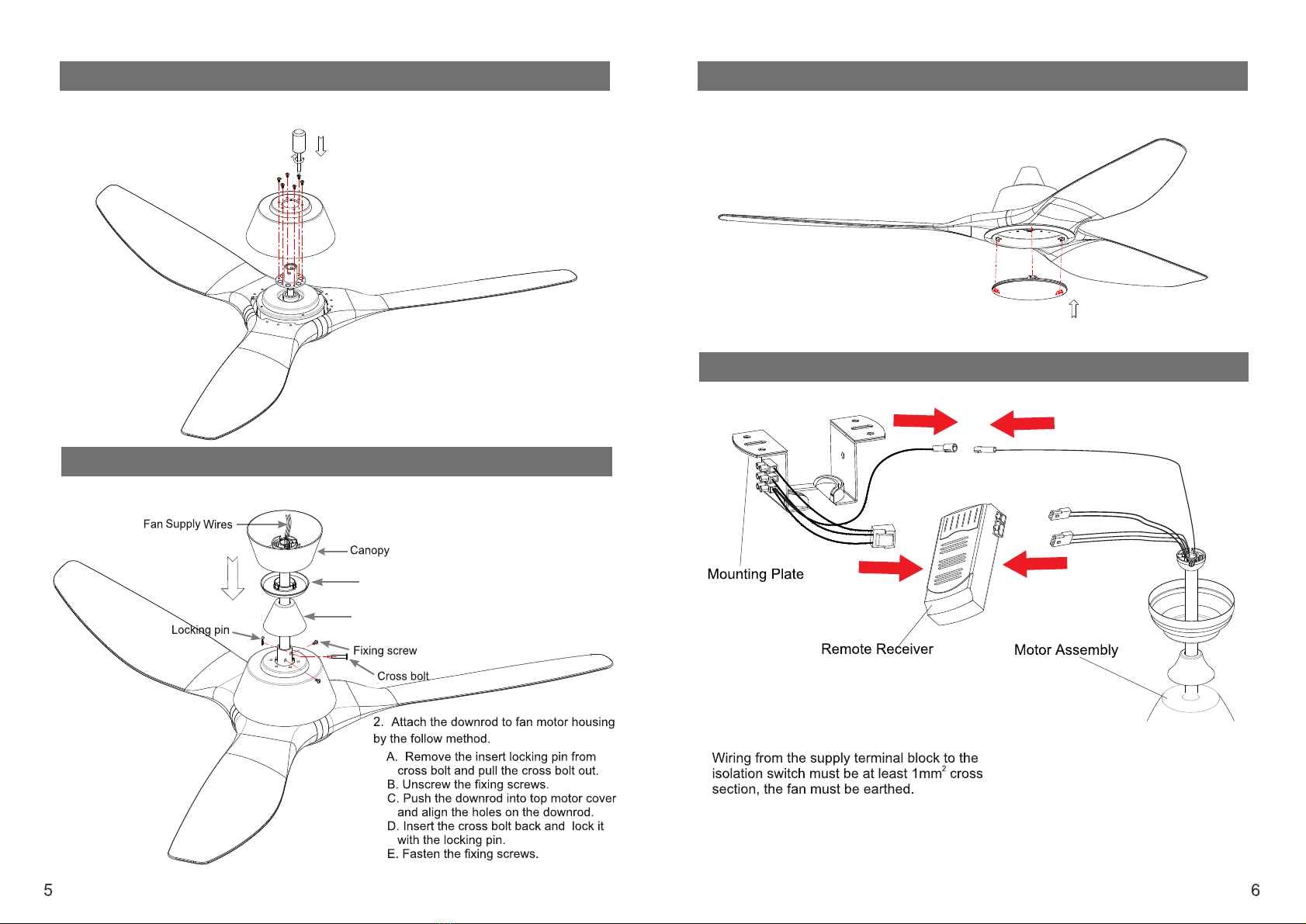
1) Unscrew 6 screws from motor assembly.
2) Take out the upper housing from motor assembly.
1) Insert the blade into motor rotating plate , lock three screws to fix
blade to the motor rotating plate .
2) Repeat step 5) for all blades.
11Canopy cover 1pc
Coupling cover
Canopy cover
6. Upper housing assembly
Align upper housing 6 holes with holes of motor , tighten 6 screws
to fix the upper housing to the motor assembly .
7. Downrod, Canopy & Coupling cover installation
1. Feed the fan supply wires from fan assembly through the downrod, coupling
cover, canopy cover and canopy.
8. Light cover assembly
Align the hooks in the light cover with notches in the light kit, press the light
cover into the light kit.
9. Power supply wire connection
Connect quick connectors as figure showed.
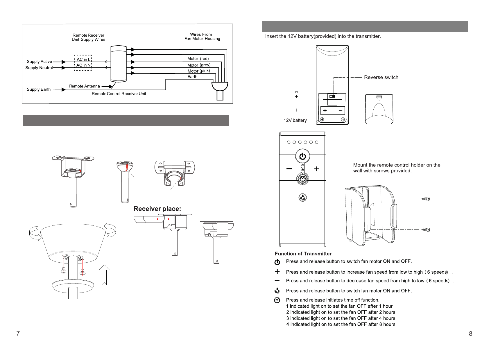
2) Unscrew the two top canopy fixing screws halfway,
attached at the bottom of the mounting bracket,
slide the top canopy up the downrod onto the mounting
bracket ; turn the canopy until fixing screws lock into
position and then fasten the screws, put the canopy
cover up to cover the screws.
For light( black)
For light( blue)
( brown)
( blue)
( yellow/green)
11. Remote cotroller operation
1) Put the hanger ball into hanger bracket, turn the downrod, let the concave
groove of hanger ball into the lugs of hanger ball plate (in hanger bracket).
Concave groove of hanger ball must be putted into the bracket lugs.
Concave
Groove
Lugs
10. Fan mounting
11 12
Indice
Altri manuali MAGNOVENT Fan


