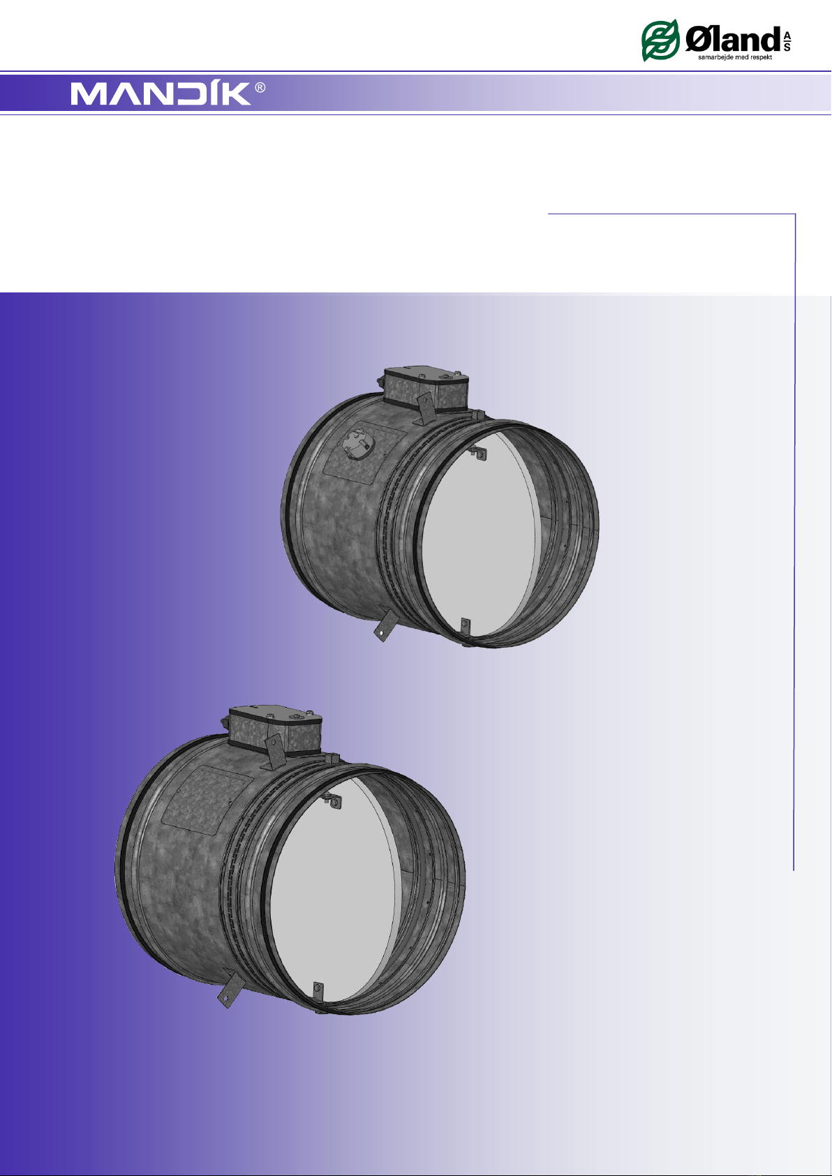
Mandik FDMC Manuale utente

FDMC, FDMC-SRD
TPM 083/12-DK
VALID FROM: 15/1/2012
FIRE DAMPER AND FIRE DAMPER-SMOKE RELIEF

TPM 083/12
2
Park Allé 366, DK-2605 Brondby
These technical specifications state a row of manufactured sizes and models of fire dampers and fire dampers - smoke
relief (further only dampers) FDMC, FDMC-SRD. It is valid for production, designing, ordering, delivery, assembly and
operation.
II. GENERAL INFORMATION 3
1. Description......................................................................................................................... 3
2. Design................................................................................................................................ 4
3. Dimensions, weights........................................................................................................... 5
4. Placement and Assembly.................................................................................................... 6
5. Statement of installations.................................................................................................... 8
III. TECHNICAL DATA 9
6. Pressure loss...................................................................................................................... 9
7. Coefficient of local pressure loss......................................................................................... 10
8. Noise data........................................................................................................................... 10
9. Electrical Components, Connection Diagrams.................................................................... 12
IV. ORDERING INFORMATION 13
10. Ordering key..................................................................................................................... 13
V. MATERIAL, FINISHING 13
11. Material............................................................................................................................. 13
VI. INSPECTION, TESTING 13
12. Inspection, testing............................................................................................................. 13
VII. TRANSPORTATION AND STORAGE 14
13. Logistic terms.................................................................................................................... 14
VIII. ASSEMBLY, ATTENDANCE, MAINTENANCE AND REVISIONS 14
14. Assembly.......................................................................................................................... 14
15. Entry into service and revisions......................................................................................... 14
I. CONTENT

TPM 083/12
3
Park Allé 366, DK-2605 Brondby
II. GENERAL INFORMATION
1. Description
1.1.
Fire dampers are shutters in piping systems of air-conditioning devices that prevent spreading
the fire and combustion products from one fire segment to the other one by means of closing the
air piping in the points of fire separating constructions.
1.4.
The damper is sealed with a silicon packing against smoke penetration after closing the blade. At
the same time, the damper blade is bed in a material which enlarges its capacity and air proofs
the air duct.
1.3.
Dampers blade automatically closes air duct using an actuating mechanism back spring. The
back spring of the actuating mechanism is started when the thermoelectrical starting mechanism
BAE 72B-S is activated, when a reset button on BAE 72B-S is pushed or when a power supply
of the actuating mechanism is stopped (for FDMC-SRD only when the power supply of the
actuating mechanism is stopped).
1.2.
Dampers are in all variants classified as EI 60 ve, ho (i o) S acc. EN 13501-3 and tested acc.
EN 1366-2.
1.5.
Dampers have one inspection hole, since the shutting device and the inspection hole can be set
into the most advantageous position (with respect to the operation and manipulation with the
control device).
1.6.
Exact damper function is provided under the following conditions:
a) Maximum air circulation speed: 12 m.s
-1
Maximum pressure difference: 1200 Pa
b) Dampers could be displaced into position “CLOSED” only in case that ventilator, or Ai
r
Handling Unit is switched off. The goal is the securing of proper closing and safe
function of Fire Damper in case of Fire.
c) The air circulation in the whole damper section must be secured as steady on whole
surface.
1.7.
Dampers are designed for macroclimatic areas with mild climate according to EN 60 721-3-3.
1.8.
Dampers are suitable for systems without abrasive, chemical and adhesive particles.
1.9.
Temperature in the place of installation is permitted to range from - 20°C to + 50°C.
1.11.
In this document are used next signs and units.
Key :
w[m.s
-1
] air velocity
p [Pa] pressure loss
L
w
[dB] level of acoustic output
[ ] pressure loss coefficient
[kg.m
-3
] density
A,B, a, c,
e, f
[mm] dimension
S [m
2
]area
1.10.
If is not noticed other way, all dimensions and weight are in millimeters and kilograms.

TPM 083/12
4
Park Allé 366, DK-2605 Brondby
2. Design
2.1.
FDMC is always equipped by actuating mechanism BLF 24-T-ST (further only "actuating
mechanism"). After being connected to power supply AC/DC 24V, the actuating mechanism
displaces the damper blade into operation position "OPEN" and at the same time it pre-stretches
its back spring. When the actuating mechanism is under voltage, the damper blade is in the
position "OPEN" and the back spring is pre-stretched. Time needed for full opening of the flap
blade from the position "CLOSED" to the position "OPEN" is maximum 140s. If the actuating
power supply is cut off (due to loss of supply voltage, activation of thermoelectrical actuating
mechanism or pushing the reset button on the thermoelectrical starting mechanism BAE 72B-S),
the back spring displaces the damper blade into the breakdown position "CLOSED". The time o
f
displacing the blade from the position "OPEN" to the position "CLOSED" takes maximum 16 s. In
case that the power supply is restored again (the blade can be in any position), the actuating
mechanism starts to re-displace the damper blade into the position "OPEN".
A thermoelectrical starting mechanism BAE 72B-S, which contains three thermal fuses Tf1 and
Tf2/Tf3, is a part of the actuating mechanism. These fuses are activated when temperature
+72 °C has been exceeded (the fuse Tf1 when the temperature around the damper and the fuses
Tf2/Tf3 when the temperature inside the air-conditioning piping has been exceeded). After the
thermal fuse Tf1 or Tf2/Tf3 has been activated, the power supply is permanently and irreversibly
cut off and the actuating mechanism, by means of the pre-stretched spring, displaces the dampe
r
blade into the breakdown position "CLOSED".
2.2.
FDMC-SRD is always equipped by actuating mechanism BLF 24-ST. It is without BAE 72B-S.
Function is similar to the BLF 24-T-ST. After being connected to power supply AC/DC 24V, the
actuating mechanism displaces the damper blade into operation position "OPEN" and at the
same time it pre-stretches its back spring. When the actuating mechanism is under voltage, the
damper blade is in the position "OPEN" and the back spring is pre-stretched. Time needed for full
opening of the flap blade from the position "CLOSED" to the position "OPEN" is maximum 140s.
If the actuating power supply is cut off (due to loss of supply voltage), the back spring displaces
the damper blade into the breakdown position "CLOSED". The time of displacing the blade from
the position "OPEN" to the position "CLOSED" takes maximum 16 s. In case that the powe
r
supply is restored again (the blade can be in any position), the actuating mechanism starts to
re-displace the damper blade into the position "OPEN".
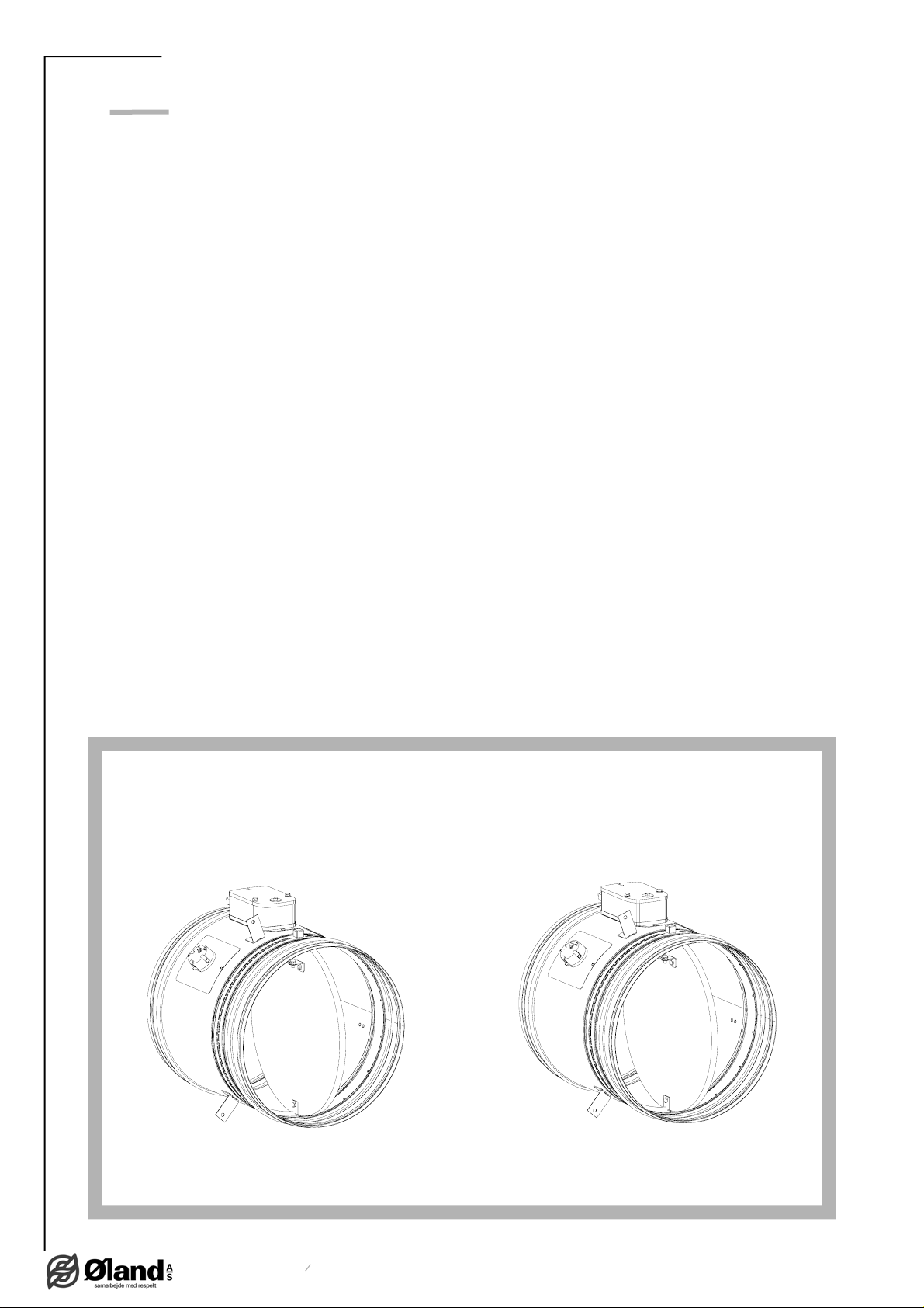
Fig. 1
FDMC FDMC-SRD

TPM 083/12
5
Park Allé 366, DK-2605 Brondby
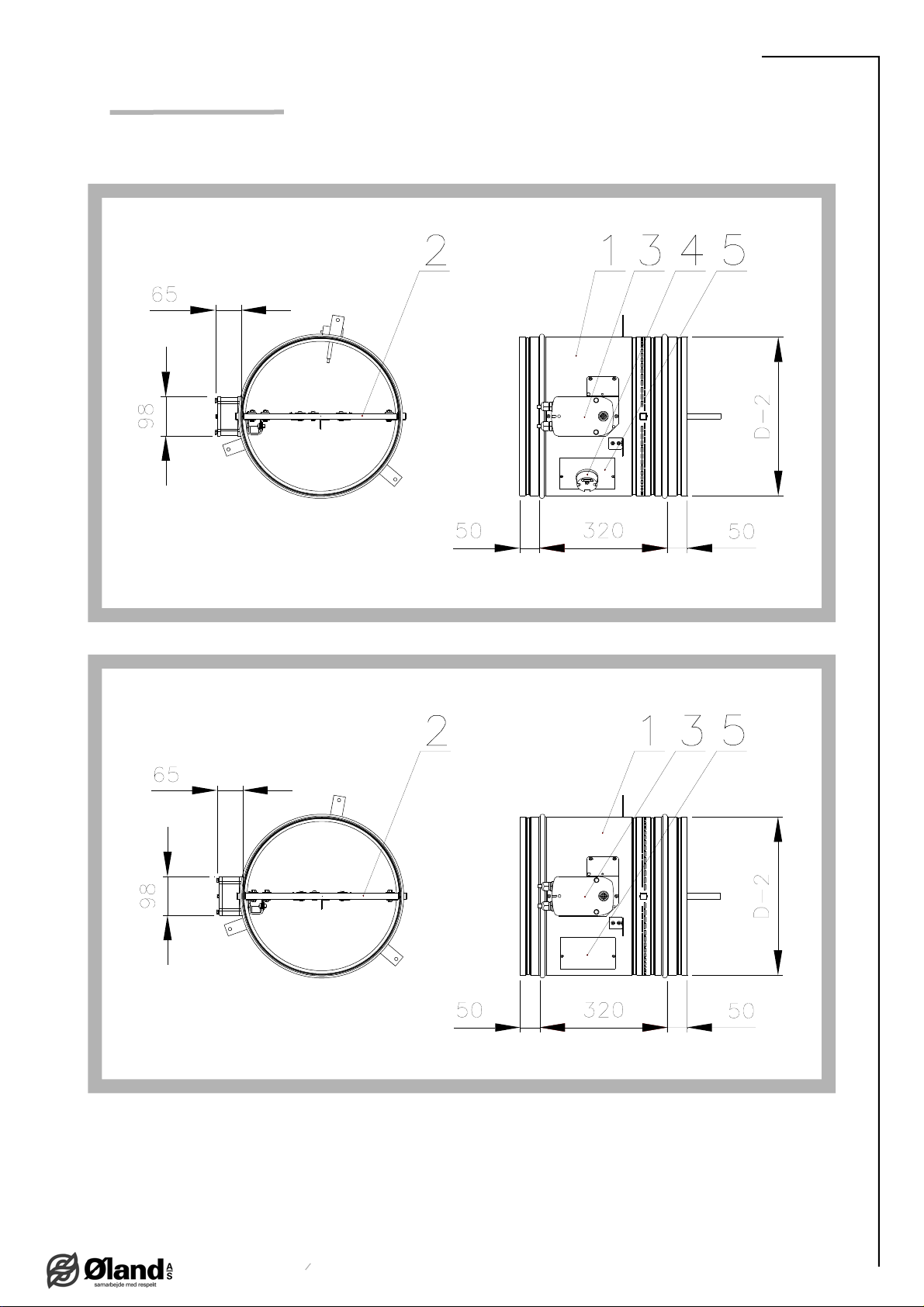
Position:
1 Damper body 4 BAE 72B-S thermoelectrical starting mechanism
2 Damper blade 5 Inspection hole covering
3 Actuating mechanism
Fig. 2 Fire damper FDMC
Fig. 3 Fire damper smoke relief FDMC-SRD
3. Dimestions, weights
3.1.
Dimensions

TPM 083/12
6
Park Allé 366, DK-2605 Brondby
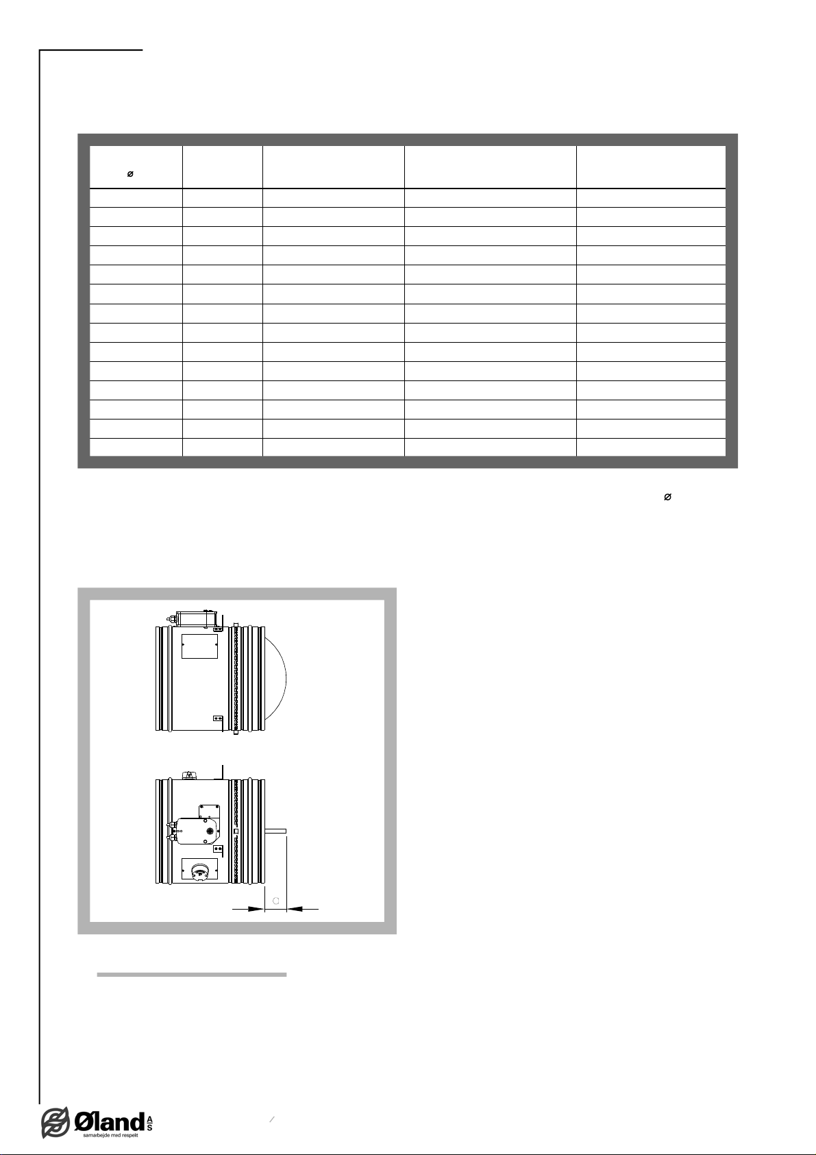
Tab. 3.2.1. Weight and effective area
Size
D a Weight
Effective area
S
ef
[m
2
]Actuating mechanism
100
-3,1 0,0036 BLF
125
-3,4 0,0068 BLF
140
-3,6 0,0092 BLF
150
-3,7 0,0109 BLF
160
-3,8 0,0129 BLF
180
-4,1 0,0172 BLF
200
-4,4 0,0222 BLF
225
-4,7 0,0293 BLF
250
95,5 0,0374 BLF
280
24 6,0 0,0484 BLF
315
41,5 6,6 0,0630 BLF
350
59 7,0 0,0793 BLF
355
61,5 7,3 0,0821 BLF
400
84 8,2 0,1065 BLF
3.2.
Weight and effective area
4. Placement and Assembly
4.1.
Fire dampers are suitable for installation in arbitrary position in vertical and horizontal passages
of fire separating constructions. Damper assembly procedures must be done so as all load
transfer from the fire separating constructions to the damper body is absolutely excluded.
Back-to-back air-conditioning piping must be hung or supported so as all load transfer from the
back-to-back piping to the damper is absolutely excluded.
3.3.
For fire damper the open damper blade overlaps the damper body from dimension 250 by the
“a” value. These values are specified in the Tab. 3.2.1
Value has to be respected when projecting related air-conditioning piping.
Fig. 4 Value “a”

TPM 083/12
7
Park Allé 366, DK-2605 Brondby
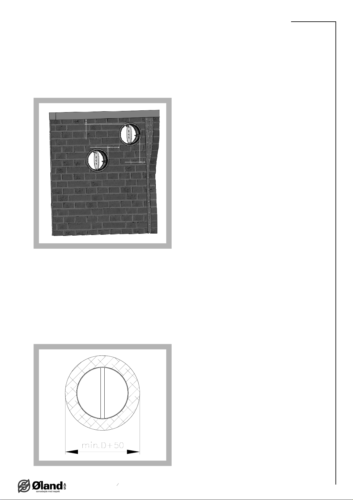
Fig. 5 Placement of the openings in the wall
min. 75
min. 75
min. 200
4.4.
The control mechanism has to be protected (covered) against damage and pollution during
installation process.
4.5.
All fire dampers has to be closed during installation process. The damper body should not be
deformed in the course of bricking in. Once the damper is built in, its blade should not grind on
the damper body during opening or closing.
4.7.
Installation opening dimensions
4.2.
To provide needed access space to the control device, all other objects must be situated at least
350 mm from the control parts of the damper. Inspection hole must be accessible.
4.3.
The distance between the fire damper and the construction (wall, ceiling) must be minimum
75 mm. In case that two or more dampers are supposed to be installed in one fire separating
construction, the distance between the adjacent dampers must be at least 200 mm according to
EN 1366-2 paragraph 13.5.
Fig. 6 Installation opening dimensions
4.6.
Round dampers are with rubber tightness and glued all the way around.

TPM 083/12
8
Park Allé 366, DK-2605 Brondby
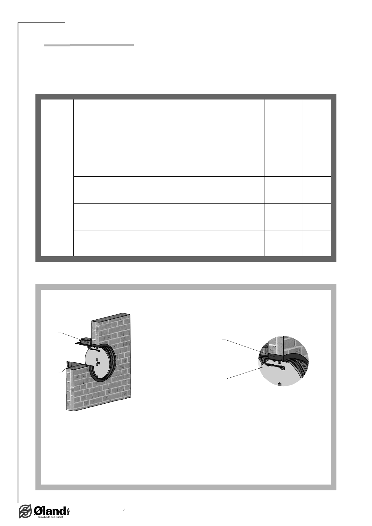
5. Statement of installations
5.1.
Statement of installations
Tab. 5.1.1. Statement of installations
Damper
size FDMC installation Classifi-
cation Figure
100-400
Damper installed on a solid wall construction. Space between damper and
wall is filled by mortar, gypsum or another approved fire sealing system
for damper installation.
EIS 60 7
Damper installed on a gypsum wall construction. Space between damper
and wall is filled by mortar, gypsum or another approved fire sealing
system for damper installation.
EIS 60 8
Damper installed on a solid ceiling construction. Space between damper
and ceiling is filled by mortar, gypsum or another approved fire sealing
system for damper installation.
EIS 60 9
Duct ended by installation shaft. Space between damper and ceiling is
filled by mortar, gypsum or another approved fire sealing system for
damper installation - solid wall construction
EIS 60 10
Duct ended by installation shaft. Space between damper and ceiling is
filled by mortar, gypsum or another approved fire sealing system for
damper installation - gypsum wall construction
EIS 60 11
Fig. 7 Installation on a solid wall construction
Position:
1 Fire damper FDMC
2 Mortar or gypsum with min. density 800 kg/m
3
or another approved fire
sealing system for damper installation
2
1
2
1

TPM 083/12
9
Park Allé 366, DK-2605 Brondby
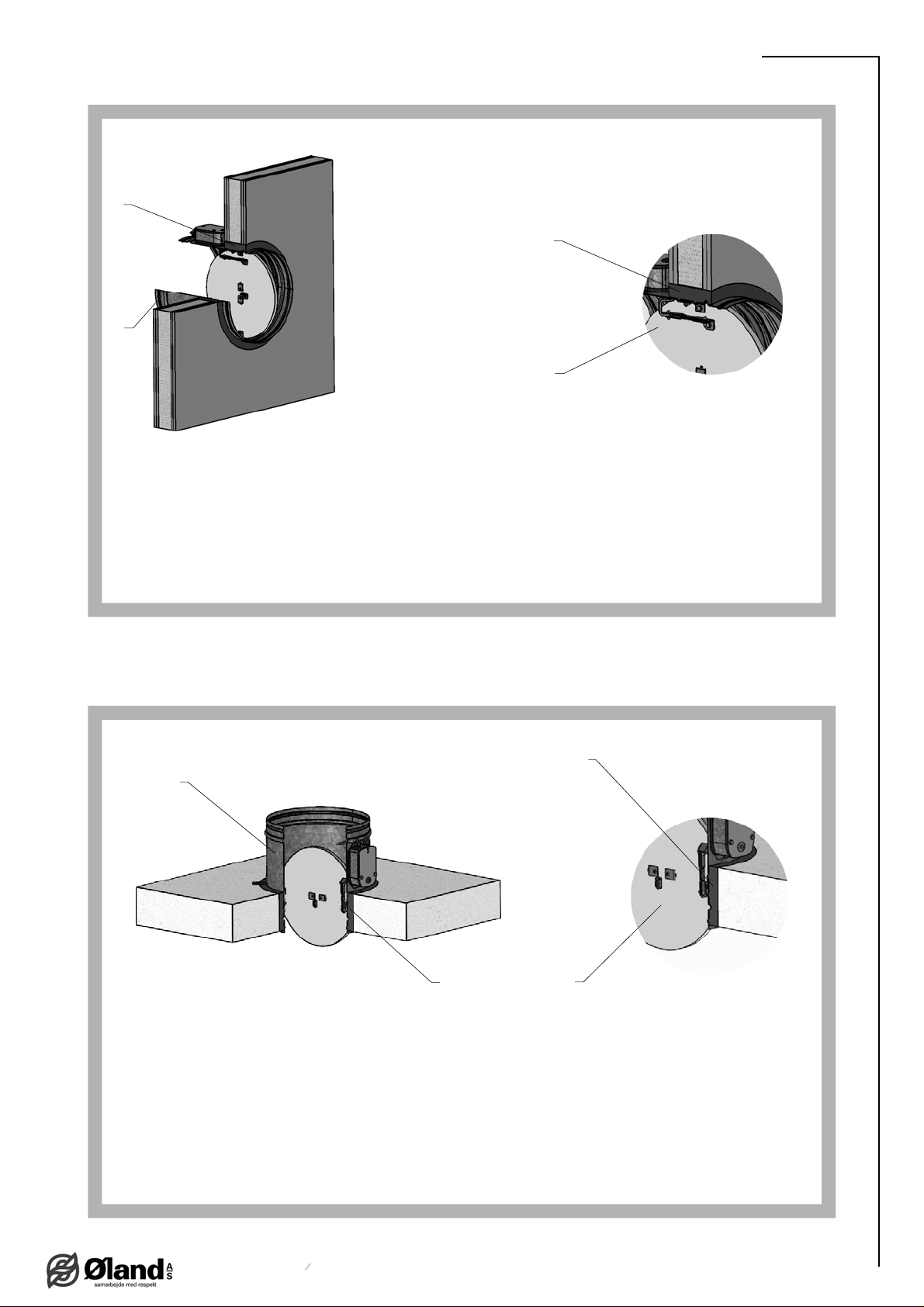
Position:
1 Fire damper FDMC
2 Mortar or gypsum with min. density 800 kg/m
3
or another approved fire
sealing system for damper installation
Fig. 8 Installation on a gypsum wall construction
2
1
2
1
Fig. 9 Installation on a ceiling wall construction
1
2
2
1
Position:
1 Fire damper FDMC
2 Mortar or gypsum with min. density 800 kg/m
3
or another approved fire
sealing system for damper installation

TPM 083/12
10
Park Allé 366, DK-2605 Brondby
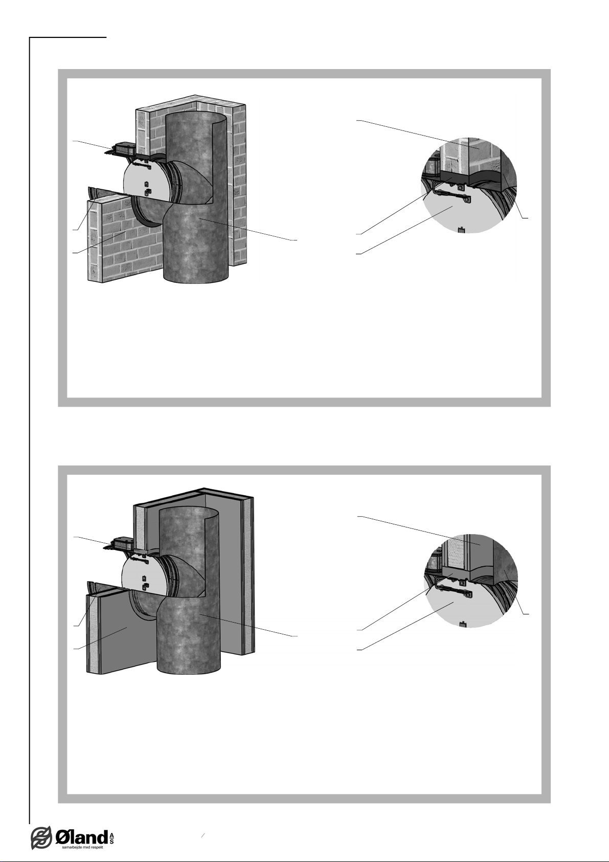
Fig. 11 Duct ended by installation shaft - gypsum wall construction
Fig. 10 Duct ended by installation shaft - solid wall construction
4
Position:
1 Fire damper FDMC 3 Duct
2 Mortar or gypsum with min. density 800 kg/m
3
or another
approved fire sealing system for damper installation
4 Installation shaft
3
1
2
1
3
2
4
4
Position:
1 Fire damper FDMC 3 Duct
2 Mortar or gypsum with min. density 800 kg/m
3
or another
approved fire sealing system for damper installation
4 Installation shaft
3
1
2
1
3
2
4
Altri manuali per FDMC
3
Questo manuale è adatto per i seguenti modelli
1
Indice
Altri manuali Mandik Serranda tagliafuoco e tagliafumo

Mandik
Mandik SEDM-L Manuale utente

Mandik
Mandik alnor FDMD Manuale utente

Mandik
Mandik FDMR Guida

Mandik
Mandik FDMQ Manuale utente

Mandik
Mandik FDMR Manuale utente

Mandik
Mandik MSD Manuale utente

Mandik
Mandik FDMB Manuale utente

Mandik
Mandik FDMR 60 Manuale utente

Mandik
Mandik FDMD Manuale utente

Mandik
Mandik FDMA-PM Manuale utente