Mandik FDMQ 120 Guida
www.mandik.com
MANDÍK, a. s. • Dobříšská 550 • 267 24 Hostomice • Czech Republic • Tel.: +420 311 706 742 • E-Mail: [email protected]
FDMQ 120
Fire damper
Technical Documentation
Installation, Commissioning, Operation, Maintenance and Service Manual
TPM 162/22
Version 2023-03-07

Fire damper - FDMQ 120Page 2 Version 2023-03-07
TPM 162/22
These technical specifications state a row of manufactured sizes and models of fire dampers FDMQ 120
It is valid for production, designing, ordering, delivery, maintenance and operation.
CONTENT
I. GENERAL.....................................................................................................................................................................................3
Description..............................................................................................................................................................................3
Design.....................................................................................................................................................................................4
Design with manual control ................................................................................................................................................4
Design with spring return actuator......................................................................................................................................6
Design with the communication and supply device..........................................................................................................12
Communication and control device BKS 24-1B and BKS 24-9A.........................................................................................17
Dimensions...........................................................................................................................................................................19
Technical parameters............................................................................................................................................................21
Placement and Installation...................................................................................................................................................27
Statement of installations.....................................................................................................................................................29
Installation in solid wall construction................................................................................................................................30
Installation outside solid wall construction.......................................................................................................................34
Installation in gypsum wall construction...........................................................................................................................36
Installation outside gypsum wall construction..................................................................................................................40
Installation in solid ceiling construction............................................................................................................................42
Shaft wall...........................................................................................................................................................................43
Suspension systems..............................................................................................................................................................45
Example of duct connection.................................................................................................................................................49
II. TECHNICAL DATA.....................................................................................................................................................................50
Pressure loss.........................................................................................................................................................................50
Noise data.............................................................................................................................................................................52
III. MATERIAL, FINISHING.............................................................................................................................................................53
Material................................................................................................................................................................................53
IV. INSPECTION, TESTING.............................................................................................................................................................53
V. TRANSPORTATION AND STORAGE...........................................................................................................................................54
Logistic terms........................................................................................................................................................................54
Warranty...............................................................................................................................................................................54
VI. ASSEMBLY, ATTENDANCE AND MAINTENANCE......................................................................................................................55
Assembly...............................................................................................................................................................................55
Entry into service and revisions.........................................................................................................................................58
Spare parts.........................................................................................................................................................................59
VII. PRODUCT DATA.....................................................................................................................................................................60
Data label..............................................................................................................................................................................60
VIII. ORDERING INFORMATION....................................................................................................................................................60
Ordering key.........................................................................................................................................................................60
Page 3Version 2023-03-07 Fire damper - FDMQ 120
TPM 162/22
I. GENERAL
Description
Working conditions
■Exact damper function is provided under the following conditions:
■maximum air velocity 12 m/s
■maximum pressure difference 1200 Pa
■the air circulation in the whole damper section must be secured steady over the entire surface.
■Dampers can be installed in position with horizontal or vertical blade axis.
■Dampers can be installed in position with actuating mechanism on top or on the side of the damper.
■Dampers are suitable for systems without abrasive, chemical and adhesive particles.
■Dampers are designed for macroclimatic areas with mild climate according to EN IEC 60 721-3-3 ed.2., class 3K22.
(Environment 3K22 is typically protected place with regulated temperature)
■Temperature in the place of installation is permitted to range from -30°C to +50°C.
Fire dampers are shutters in ducts of air-conditioning devices
that prevent the spread of fire and combustion products from
one fire segment to the other one by means of closing the
duct in the points of fire separating constructions.
Damper blade automatically closes air duct using a closing
spring or a spring return actuator. The closing spring is
actuated by pressing a button on the manual control or by
melting a thermal fuse.
The return spring of the actuator is actuated when a
thermoelectric activation device BAT is activated, when a test
button on BAT is pressed or when power supply of the
actuator is interrupted.
After closing the blade, the damper is sealed with silicon
against smoke penetration. On request by customer, the
damper can be supplied silicon-free. In the closed position,
the damper is also sealed with material which increases its
volume due to increasing temperature and air proofs the air
duct.
Dampers have two inspection openings.
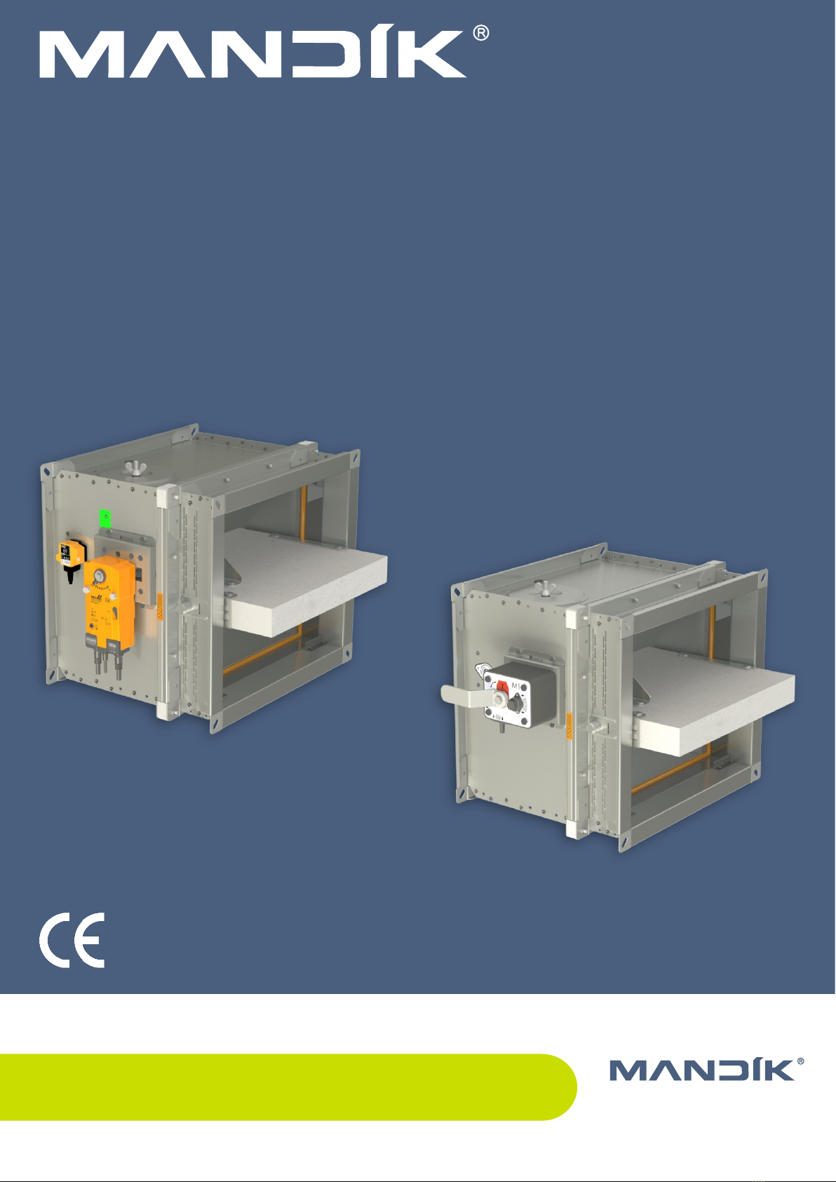
FDMQ 120 with spring return actuator FDMQ 120 with manual control
Damper characteristics
■CE certified acc. to EN 15650
■Tested in accordance with EN 1366-2
■Classified acc. to EN 13501-3+A1
■External Casing leakage class min. C acc. to EN 1751
■Internal leakage min. class 2 acc. to EN 1751
■Cycling test in class C10000 acc. to EN 15650
■Corrosion resistant acc. to EN 15650
■Certificate of constancy of performance No. 1391-CPR-2022/0153
■Declaration of Perfomance No. PM/FDMQ 120/01/22/1
■Hygienic assessment of fire dampers - Report No. 1.6/pos/19/19c
Fire damper - FDMQ 120Page 4 Version 2023-03-07
TPM 162/22
Design
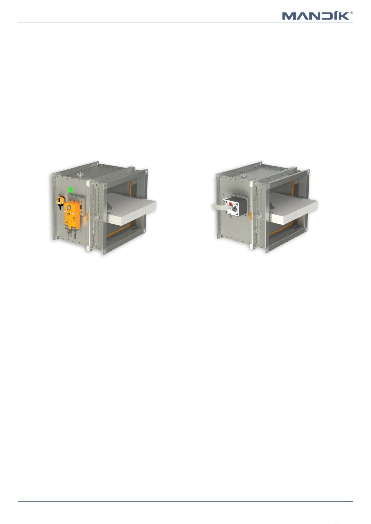
Design with manual control
■Design .01 with manual control can be complemented
with a limit switch signaling of the damper blade position
"CLOSED".
■Cable is connected directly to limit switch.
■Limit switch detail → see page 5
Design .11
■Design .01 with manual control can be complemented
with two limit switches signaling of the damper blade
position "CLOSED" and "OPEN".
■Cables are connected directly to limit switches.
■Limit switch detail → see page 5
Design .80
■Design with manual control with a thermal fuse which
actuates the shutting device, after the nominal activation
temperature 72°C has been reached.
■Automatic initiation of the manual control is not activated
if the temperature does not exceed 70°C.
■In case that other activation temperatures are required,
thermal fuses with nominal activation temperature
+104°C or +147°C can be supplied (this requirement must
be specified in the order).
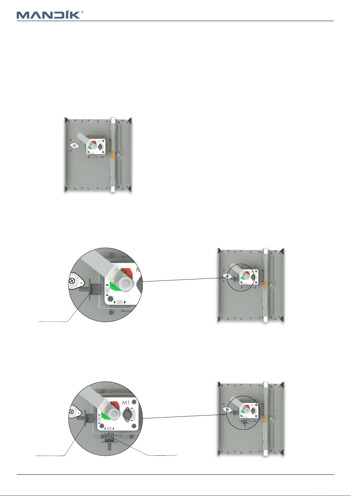
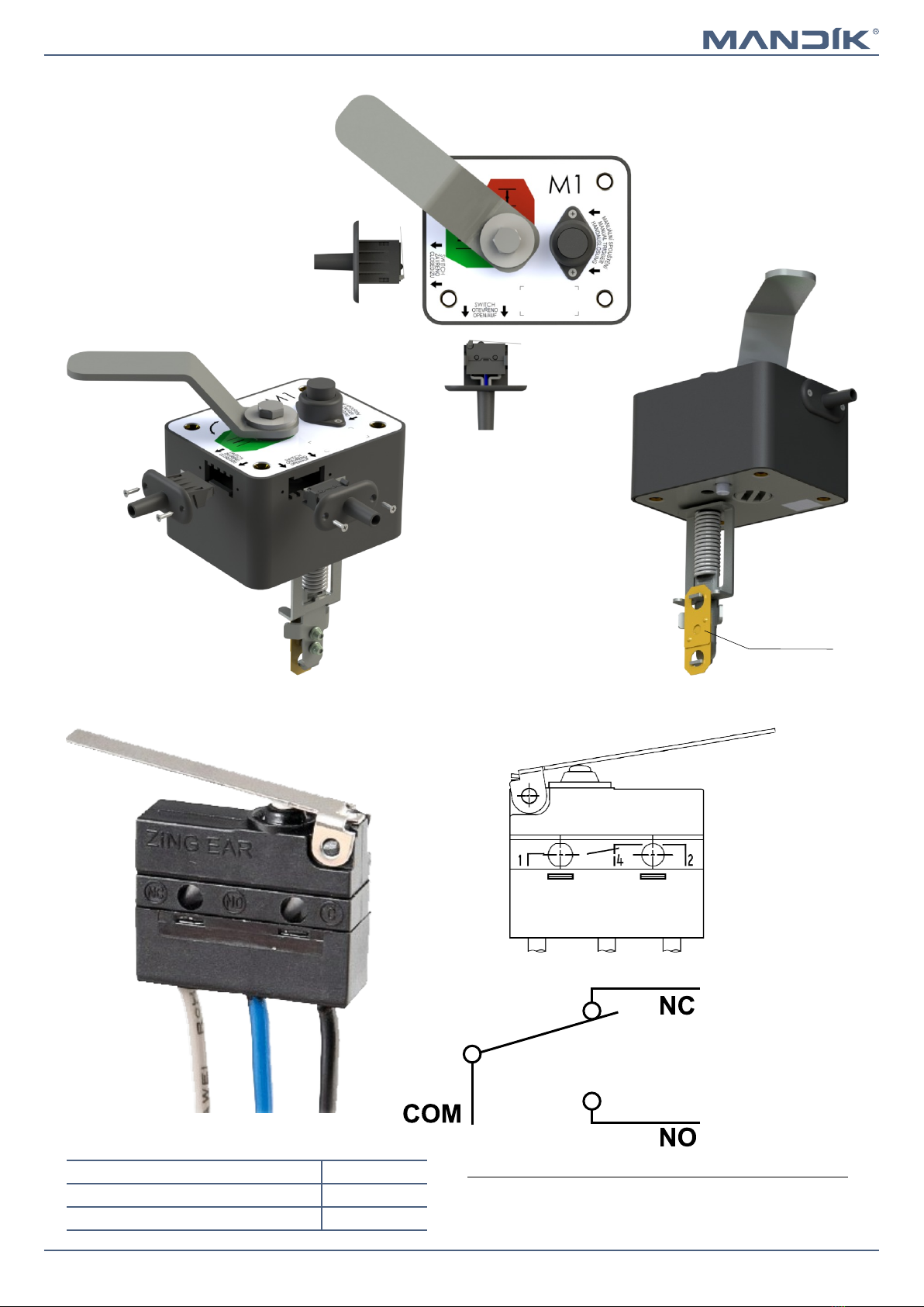
Design .01
ATTENTION:
■Manual controls are produced in five sizes M1 to M5,
difference is only in size of a closing spring, which closes
the fire damper.
■For the size of fire dampers is always assigned the size of
the manual control → see pages 21 to 26
■It is not recommended to use different size of the manual
control than given by the manufacturer, otherwise there
is a risk of damaging the fire damper.
Design .01
Design .11
Limit switch
“CLOSED”
Design .80
Limit switch
“CLOSED”
Limit switch
“OPEN”
Page 5Version 2023-03-07 Fire damper - FDMQ 120
TPM 162/22
Nominal voltage and maximal current AC 230V / 5A
Class of protection IP 67
Working temperature
-25°C … +120°C
Limit switch G905-300E03W1
This limit switch is possible to connect in two following ways
■CUT-OFF if the arm is moving … connect wire 1+2
■SWITCH-ON if the arm is moving … connect wire 1+4
1(COM) - black wire
2(NC) - gray wire
4(NO) - blue wire
Manual control
Thermal fuse
Fire damper - FDMQ 120Page 6 Version 2023-03-07
TPM 162/22
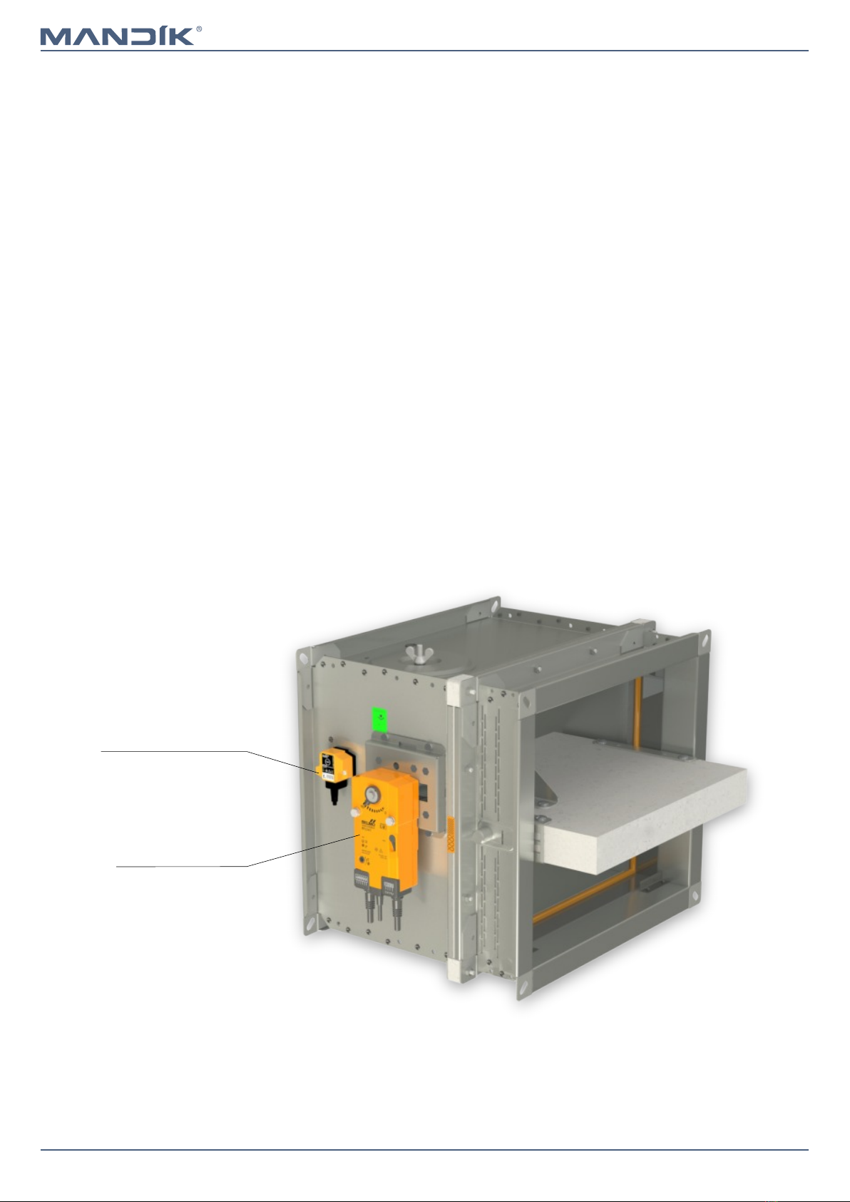
Design with spring return actuator
■The fire dampers are equipped with Belimo spring return
actuators with thermoelectric activation device BAT. The
spring return actuator types are BFL, BFN or BF depending
on the damper size. (Further mentioned as „actuator“).
■After being connected to power supply 230V or AC/DC
24V, the actuator rotates the damper blade to the
operating position "OPEN" and at the same time pre-
stretches its return spring.
■When the actuator is power supplied, the damper blade is
in the position "OPEN" and the return spring is pre-
stretched.
■Time needed for full opening of the damper blade from
the position "CLOSED" to the position "OPEN" is maximum
120 sec. If the actuator power supply is interrupted (due
to loss of supply voltage, or pressing a test button on the
thermoelectric activation device BAT), the actuator
rotates the damper blade to the breakdown position
"CLOSED".
■The time of closing the damper blade from the position
"OPEN" to the position "CLOSED" takes maximum 20 sec.
■In case that the power supply is restored again (the blade
can be in any position), the actuator starts to rotate the
damper blade back to the position "OPEN".
■A thermoelectric activation device BAT, which contains
two thermal fuses Tf1 and Tf2, is an integral part of the
actuator.
■These fuses are activated when temperature +72°C has
been reached (the fuse Tf1 due to temperature outside
the duct and the fuse Tf2 due to temperature inside the
duct). The thermoelectric activation device can also be
equipped with a Tf2 thermal fuse type ZBAT 95/120/140
(must be specified in the order). In this case, the activation
temperature inside the duct is +95°C, +120°C or +140°C
(depending on the type).
■After the thermal fuse Tf1 or Tf2 has been activated, the
power supply is permanently and irreversibly interrupted
and the actuator, by means of the pre-stretched spring,
rotates the damper blade into the breakdown position
"CLOSED".
■Signalisation of damper blade position "OPEN" and
"CLOSE" is provided by two microswitches.
Design .40 and .50
Design .40 and .50
Spring return actuator
Thermoelectric
activation device BAT
Page 7Version 2023-03-07 Fire damper - FDMQ 120
TPM 162/22
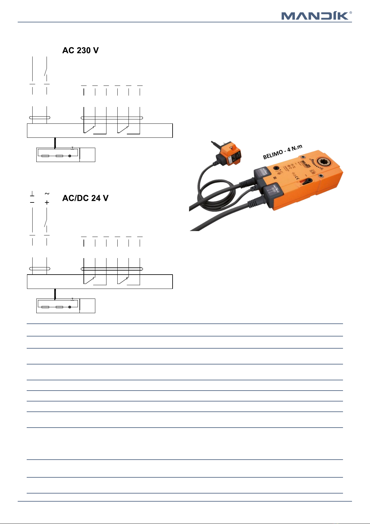
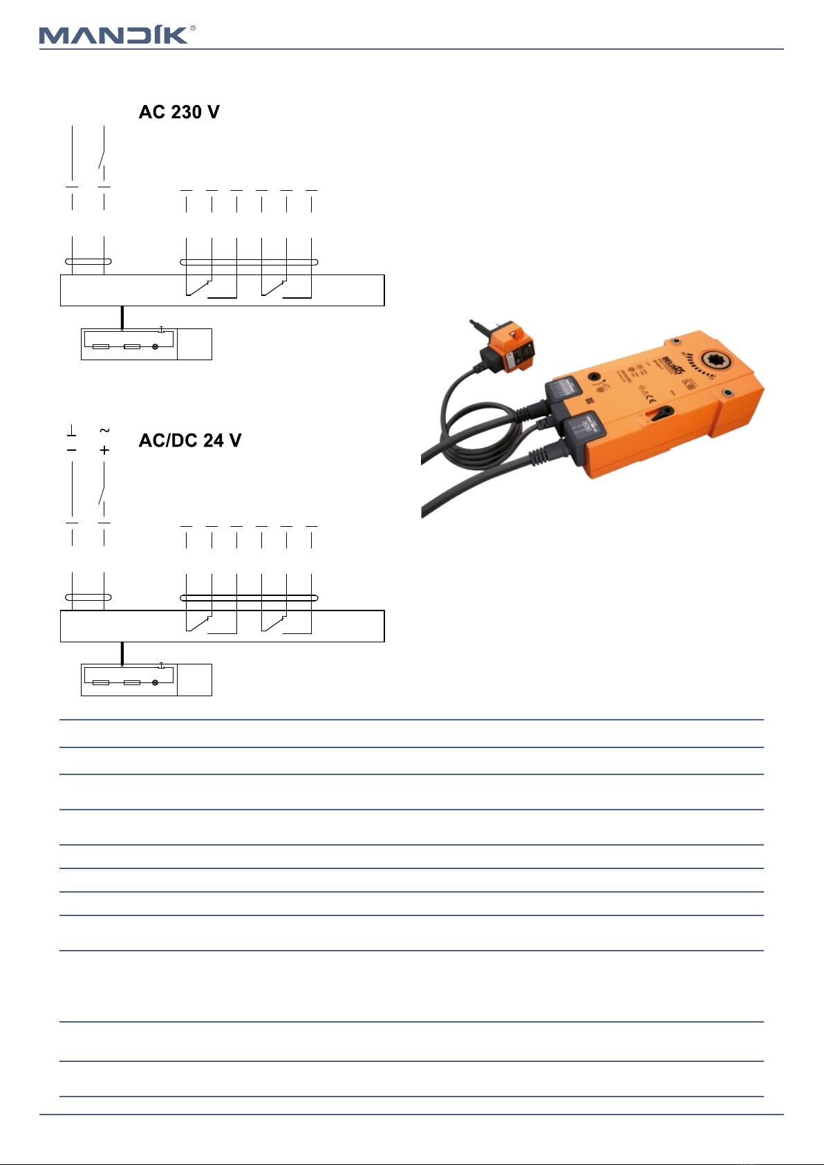
Actuator BELIMO BFL 230-T
Actuator BELIMO BFL 24-T(-ST)
BELIMO - 4 N.m
Actuator BELIMO BFL 230-T, BFL 24-T(-ST)
Actuator BELIMO - 4 Nm BFL 230-T BFL 24-T(-ST)
Power voltage AC 230 V
50/60Hz
AC/DC 24 V
50/60Hz
Power consumption - in operation
- in rest position
3,5/5 W
1,1/2,1 W
2,5/4 W
0,8/1,4 W
Dimensioning 6,5/10 VA (Imax 4 A @ 5 ms) 4/6 VA (Imax 8,3 A @ 5 ms)
Protection class II III
Degree of protection IP 54
Running time - motor
- spring return
< 60 s
~ 20 s
Ambient temperature
- normal duty
- safety duty
- non-operating temperature
-30°C … +55°C
The safe position will be attained up to max. +75°C
-40°C … +55°C
Connection - supply/control
- auxiliary switch
cable 1 m, 2 x 0,75 mm² (BFL 24-T-ST) with 3-pin plug-in connectors
cable 1 m, 6 x 0,75 mm² (BFL 24-T-ST) with 6-pin plug-in connectors
Response temperature thermal fuse duct outside temperature +72°C
duct inside temperature +72°C
S2S1 S3 S5S4 S6
2
1
<5° <80°
N L1
BAT
Tf Tf LED
S2S1 S3 S5S4 S6
2
1
<5° <80°
BAT
Tf Tf LED
Fire damper - FDMQ 120Page 8 Version 2023-03-07
TPM 162/22
Actuator BELIMO BFN 24-T(-ST)
BELIMO - 9 N.m
Actuator BELIMO BFN 230-T, BFN 24-T(-ST)
Actuator BELIMO - 9 Nm BFN 230-T BFN 24-T(-ST)
Power voltage AC 230 V
50/60Hz
AC/DC 24 V
50/60Hz
Power consumption - in operation
- in rest position
3,5/5 W
1,1/2,1 W
2,5/4 W
0,8/1,4 W
Dimensioning 6,5/10 VA (Imax 4 A @ 5 ms) 4/6 VA (Imax 8,3 A @ 5 ms)
Protection class II III
Degree of protection IP 54
Running time - motor
- spring return
< 60 s
~ 20 s
Ambient temperature
- normal duty
- safety duty
- non-operating temperature
-30°C … +55°C
The safe position will be attained up to max. +75°C
-40°C … +55°C
Connection - supply/control
- auxiliary switch
cable 1 m, 2 x 0,75 mm² (BFN 24-T-ST) with 3-pin plug-in connectors
cable 1 m, 6 x 0,75 mm² (BFN 24-T-ST) with 6-pin plug-in connectors
Response temperature thermal fuse duct outside temperature +72°C
duct inside temperature +72°C
Actuator BELIMO BFN 230-T
S2S1 S3 S5S4 S6
2
1
<5° <80°
N L1
BAT
Tf Tf LED
S2S1 S3 S5S4 S6
2
1
<5° <80°
BAT
Tf Tf LED
Page 9Version 2023-03-07 Fire damper - FDMQ 120
TPM 162/22
Actuator BELIMO BF 230-TN
Actuator BELIMO BF 230-TN, BF 24-TN(-ST)
Actuator BELIMO - 18 Nm BF 230-TN BF 24-TN(-ST)
Power voltage AC 230 V
50/60Hz
AC/DC 24 V
50/60Hz
Power consumption - in operation
- in rest position
8 W
3 W
7 W
2 W
Dimensioning 12,5 VA (Imax 500 mA @ 5 ms) 10 VA (Imax 8,3 A @ 5 ms)
Protection class II III
Degree of protection IP 54
Running time - motor
- spring return
120 s
~ 16 s
Ambient temperature
- normal duty
- safety duty
- non-operating temperature
-30°C … +50°C
The safe position will be attained up to max. +75°C
-40°C … +50°C
Connection - supply/control
- auxiliary switch
cable 1 m, 2 x 0,75 mm²
cable 1 m, 6 x 0,75 mm²
(BF 24-T-ST) with plug-in connectors
Response temperature thermal fuse duct outside temperature +72°C
duct inside temperature +72°C
BELIMO - 18 N.m
Actuator BELIMO BF 24-TN (-ST)
S2S1 S3 S5S4 S6
2
1
<5° <80°
N L1
BAT
Tf Tf LED
S2S1 S3 S5S4 S6
2
1
<5° <80°
BAT
Tf Tf LED
Fire damper - FDMQ 120Page 10 Version 2023-03-07
TPM 162/22
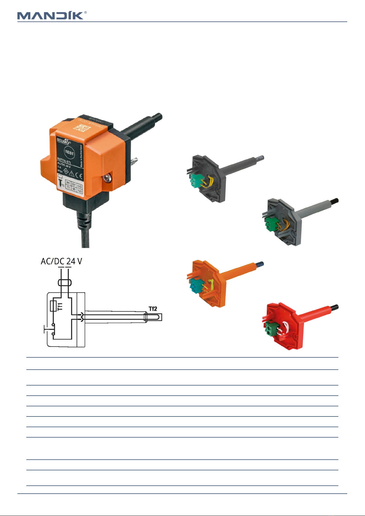
Thermoelectric activation device BAT 72 (95/120/140)
Power voltage AC/DC 24 V
50/60Hz
Rated current 1 A
AC/DC throughput resistance <1 Ω
Protection class III
Degree of protection IP 54
Probe length 65 mm
Ambient temperature
Storage temperature
Ambient humidity
-30°C … +50°C
-40°C … +50°C
Max. 95% RH, non-condensing
Connection supply Cable 1 m, 2 x 0.5 mm², Betaflam cable heatresistant up to 145°C
Response temperature thermal fuse Duct inside temperature +72 (95/120/140)°C
Duct outside temperature +72 (95/120/140)°C
Thermoelectric activation device BAT
■If the thermal fuse Tf1 is interrupted (due to temperature
outside the duct), it is necessary to replace the spring
return actuator. Thermoelectric activation device BAT is
integral part of the actuator.
■If the thermal fuse Tf2 is interrupted (due to temperature
inside the duct) , only the spare part ZBAT 72
(95/120/140) needs to be replaced (acc.to the activation
temperature).
■When one of the thermal fuses responds, the supply
voltage is interrupted permanently and irreversibly.
■The function (interruption of the supply voltage) can be
checked by pressing the test button.
■Installation is carried out with the pre-assembled, self-
tapping screws.
Temperature of thermal fuses
Spare parts are supplied only on the basis of an order.
BELIMO ZBAT 72
Black (BK) = 72°C (standard)
BELIMO ZBAT 95
Grey (GY) = 95°C
BELIMO ZBAT 120
Orange (OG) = 120°C
BELIMO ZBAT 140
Red (RD) = 140°C
Altri manuali per FDMQ 120
1
Indice
Altri manuali Mandik Serranda tagliafuoco e tagliafumo

Mandik
Mandik FDMB Manuale utente

Mandik
Mandik MSD Manuale utente

Mandik
Mandik MSD Manuale utente

Mandik
Mandik SEDM Manuale utente

Mandik
Mandik FDMB Series Manuale utente

Mandik
Mandik FDMC Series Manuale utente

Mandik
Mandik FDMQ Manuale utente

Mandik
Mandik FDMQ Manuale utente

Mandik
Mandik NKTM Manuale utente

Mandik
Mandik SEDM Manuale utente

Mandik
Mandik SEDS Manuale utente

Mandik
Mandik FDMS Series Manuale utente

Mandik
Mandik FDMQ 120 Manuale

Mandik
Mandik FDMS Manuale utente

Mandik
Mandik FDMB Manuale utente

Mandik
Mandik alnor FDMD Manuale utente

Mandik
Mandik FDMA Manuale utente

Mandik
Mandik FDMC Manuale utente

Mandik
Mandik SEDS-L Manuale utente

Mandik
Mandik SEDM Guida


