IS 30 T
GB
4.2 Typical installation with generator above
the waterline
See Fig. 3
1 Sea exhaust
2 Silencer
3 Muffler
4 Water filter
5 Main system tap
6 Sea intake
7 Drain tap
A Pipes - inner diameter 75 mm
B Pipes - inner diameter 25 mm
C Pipes - inner diameter 16 mm
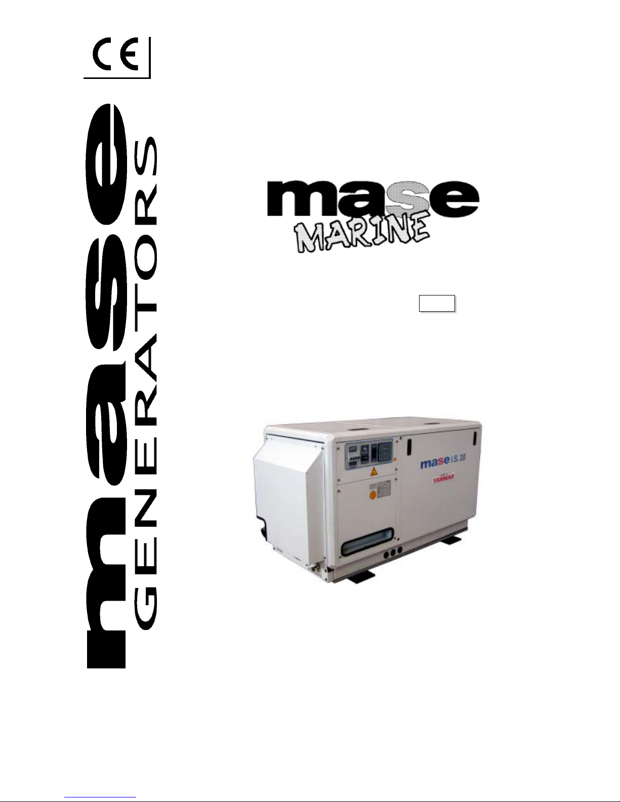
4.3 Typical installation with generator below
the waterline
See Fig. 4
1 Sea exhaust
2 Silencer
3 Muffler
4 Water filter
5 Main system tap
6 Sea intake
7 Drain tap
8 Antisiphon valve
9 Drainage
A Pipes - inner diameter 75 mm
B Pipes - inner diameter 25 mm
C Pipes - inner diameter 16 mm
D Pipes - inner diameter 14 mm
• It is very important to respect the distances shown in
the installation diagrams.
• The mufflers, (Fig. 3 and 4, ref. 3), have the function
of collecting the water left in the exhaust pipes when
the generator engine is turned off and preventing that
it flows into the engine through the manifold and the
exhaust valve. For this reason it is essential to respect
the position of the muffler and the length of the pipes
as indicated in the installation diagram.
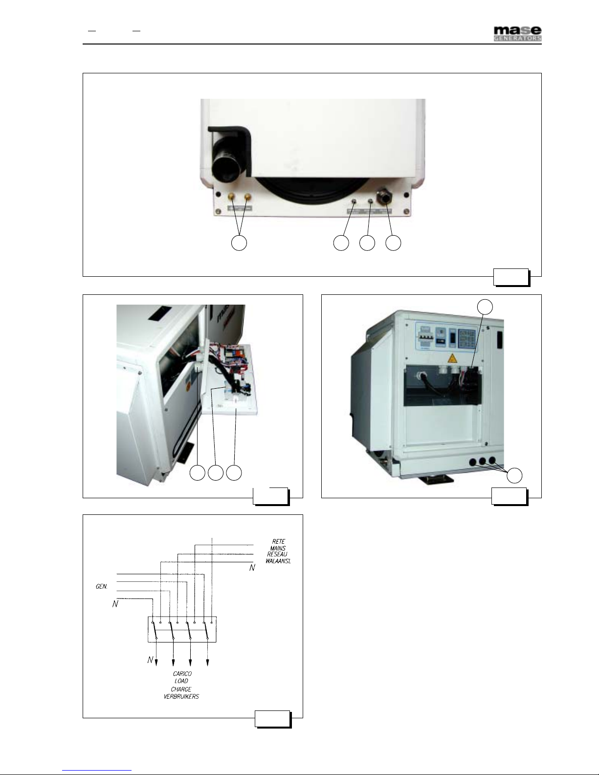
4.4 Components
The sea water intake system must be separate from the
one for the engines propelling the boat.
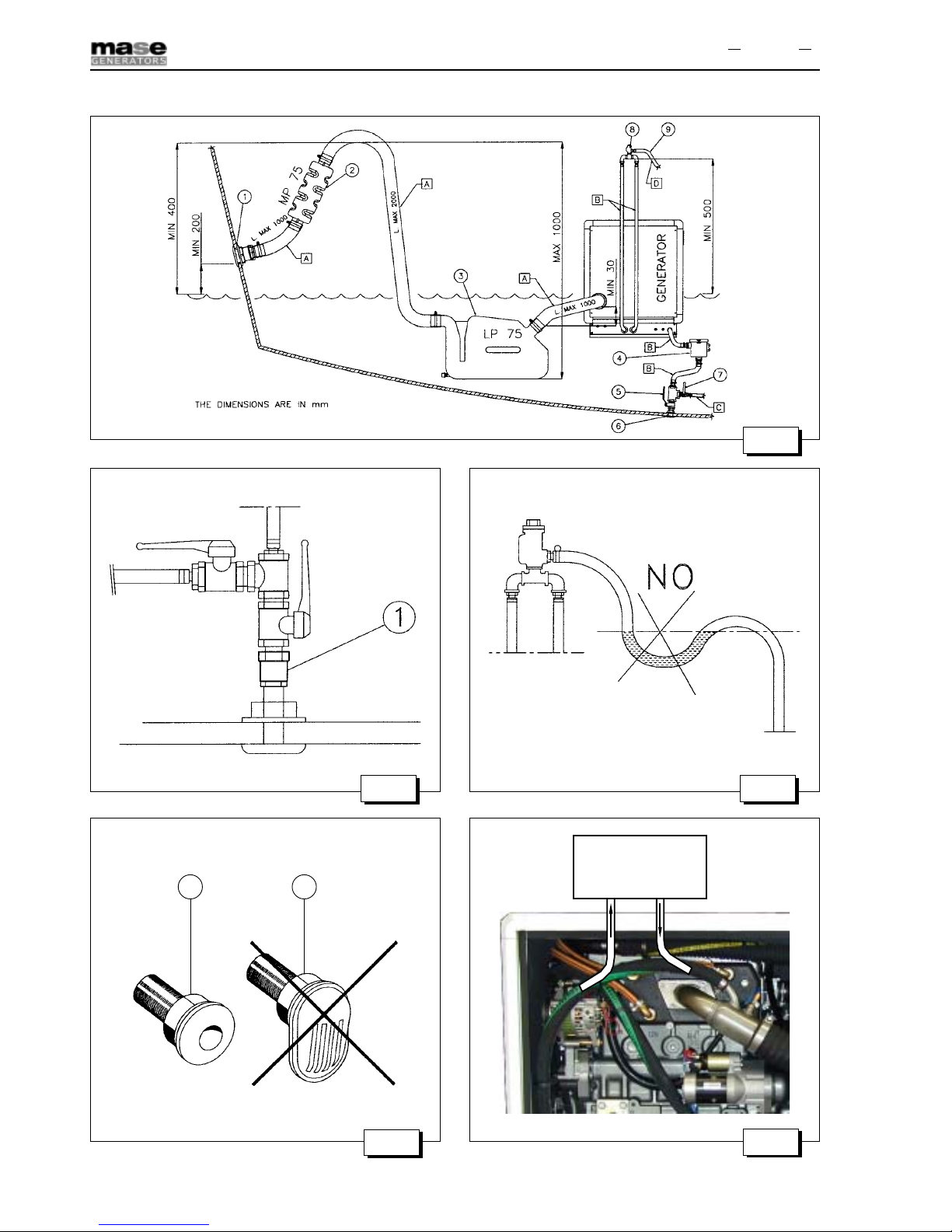
•Direct sea intake 1/2".
If the unit is installed more than 1 m above the water-
line, a check valve should be fitted after the sea intake,
(Fig. 5, ref. 1), to prevent the water circuit emptying when
the motor is off. If this empties, the rotor of the water
pump might be damaged during start up; for the same
reason, when the unit is first started up, the suction tube
from the valve to the pump should be filled manually.
•Ball tap 1/2", (general).
•Ball tap 1/2", (drainage). This is used to drain the
cooling system of the electric generator for general
maintenance or when a long period of inactivity is
expected.
•Water filter, (can be inspected). This must provide
efficient protection for the cooling circuit from the
entrance of mud, sand and seaweed.
Rate of flow: 25 l/min.
The filter mesh should be very fine. Mesh 2 - 470 micron
is recommended; other sizes do not give good filter
performance.
•Anti-siphon valve. This is a valve that brings the
cooling circuit back to atmospheric pressure when
the motor is turned off, thus avoiding the formation
of siphons. It’s use obligatory when the base of
the generator group is under the water line and it
must be positioned at least 50 cm above sea level,
(see Fig. 4).
Anti-siphon valve must be inserted between the inlet of
the sea water pump and mixing elbow as indicated in
Fig. 8.
The drainage duct of the anti-siphon valve must run
beneath the valve itself in order to prevent water
accumulating in the duct, which should always remain
empty to allow air to pass through when the unit is
switched off, (see Fig. 6).
It is recommended that the drainage pipe from the anti-
siphon valve be fed into the bilge, as small amounts of
water might be drained through it during normal
operation.
Run the pipes connected to the antisiphon valve through
the holes shown in Fig. 2, ref. 2.