matev FPS-JD 3036 Istruzioni per l'installazione

matev GmbH
Nürnberger Str. 50
90579 Langenzenn
T +49 (0) 9101 9087 -0
F +49 (0) 9101 9087 -20
info@matev.eu
www.matev.eu
Version 03/2010
Original Operating Manual
Front power lift
FPS-JD 3036
Front power lift 131 7161
Joystick set triple 131 7136
Joystick set single 131 7160
Conversion kit orig. JD frontloader 131 7224

Contents
Table of contents
1About this operating manual ......................................................................................3
2Safety.............................................................................................................................4
2.1 Intended use...................................................................................................................4
2.2 Qualification of personnel...............................................................................................5
2.3 General safety instructions.............................................................................................5
2.4 Special safety instructions..............................................................................................6
3Installation.....................................................................................................................7
3.1 Mounting the front power lift...........................................................................................7
3.1.1 Delivery status................................................................................................................7
3.1.2 Preparation.....................................................................................................................8
3.1.3 Mounting the front power lift...........................................................................................8
3.2 Use with frontloader......................................................................................................11
3.2.1 Mounting the upper link holder.....................................................................................11
3.2.2 Dismounting the lift arms..............................................................................................11
3.3 Mounting an original JD hood guard............................................................................12
3.4 Mounting the joystick set..............................................................................................14
3.4.1 Mounting the joystick element......................................................................................14
3.4.2 Attaching the control device.........................................................................................15
3.4.3 Connection in assignments on the single control valve...............................................16
3.4.4 Connection assignments on the triple control valve....................................................16
3.4.5 Connecting the control device to the tractor hydraulic system....................................17
3.4.6 Mounting the rear hydraulic extension kit....................................................................18
3.4.7 Mounting the front hydraulic kit (only for joystick set triple, art. no.: 131_7136).........18
4Operation.....................................................................................................................19
4.1 Attachment variants of the coupling triangle................................................................19
4.2 Coupling and uncoupling implements..........................................................................20
4.3 Lowering safeguard for the front power lift ..................................................................20
5Maintenance................................................................................................................21
5.1 General.........................................................................................................................21
5.2 Service..........................................................................................................................21
5.2.1 Maintaining the hydraulic system.................................................................................22
6Repair...........................................................................................................................22
7Disposal.......................................................................................................................23
8Warranty ......................................................................................................................23
9Technical data and accessories...............................................................................23
9.1 Technical data..............................................................................................................23
9.2 Accessories..................................................................................................................23
10 List of illustrations .....................................................................................................24
11 EC Declaration of Conformity...................................................................................25


About this operating manual
Page 3
1 About this operating manual
Dear customer!
Thank you for purchasing this device, we appreciate your trust.
In order to optimally use your new front power lift it is necessary to read this operating
manual completely and conscientiously and to understand it before first use of the device.
To obtain the long service life that matev products are known for, careful and conscien-
tious maintenance is a strict requirement. To properly maintain your front power lift it is
strictly necessary that you have carefully read this operating manual. Moreover it is not
possible for matev to assume liability for damage that is attributed to improper use or
non-intended use of the front power lift.
Keep this operating manual where it is easily accessible. This will enable you to refer to
important information and handling instructions as needed.
Listings with bullet points are marked as follows:
•Text
•Text
•Text . . .
Handling instructions are marked in the sequence in which they should be executed, as
follows:
2. Text
3. Text
3. Text . . .
This device is subject to change in the interest of technical progress. All
information, illustrations, and technical specifications represent the latest
status at the time this manual was published. The manufacturer reserves the
right to make changes at any time in the interest of technical progress.
However there is no obligation to extend any changes made to previously
delivered front power lifts or associated accessories.

Safety
Page 4
2 Safety
Guidelines and instructions with which you must comply are summarized in this section.
Personnel who install, operate and maintain the device, must have read and understood
this operating manual.
2.1 Intended use
The front power lift should only be mounted on type JD 3036 tractors, it is used for ac-
commodating small to medium-sized implements, such as snow blades, sweepers, etc.
and should only be connected and operated with such implements. Please note that you
must avoid overloading the front axle even in heavy-duty implementation (e.g. snow re-
moval). The permissible axle load is specified in the appropriate documentation provided
by the tractor manufacturer.
Attention!
The front power lift should not be charged with downward pressure via the
tractor's hydraulic system! For implements that contact the ground or roll
on the ground in operation the tractor hydraulic system must be switched to
the float setting! Strictly comply with the manufacturer's recommendation!
The front power lift is not suitable for lifting people or for use as a work plat-
form!
In addition compliance with the service and maintenance guidelines is a component of in-
tended use. Moreover intended use includes exclusive use of original spare parts and
supplemental equipment, or use of such parts and equipment that meet the technical re-
quirements specified by the manufacturer.
All other uses are excluded.
Non-intended use causes:
•Health hazards for the operator or for third parties
•Damage to the tractor and the attachments
•Immediate invalidation of the guarantee
•Environmental damage
To avoid accidents and reduce the risk of accidents the relevant accident prevention
regulations and the other generally acknowledged occupational health and safety and
road traffic regulations apply without limitation.
Changes to the front power lift and/or the associated accessories invalidate the guaran-
tee and exclude any liability on the part of the manufacturer for damage due to the
changes.

Safety
Page 5
2.2 Qualification of personnel
Only persons 18 years of age or older, or instructed persons should install, operate, and
maintain the implements. The operator must have read and understood this operating
manual.
2.3 General safety instructions
General safety instructions are explained in this section. These safety instructions are
used in the subsequent sections. In addition to the safety aspect, you will save money
and work time if you follow these safety instructions.
Danger!
Severe injury to the operator or third parties occurs.
Follow the safety instruction.
Attention!
Minor injury to the operator or third parties can
occur. The tractor, the implements, or the environment can be damaged.
Comply with the safety instruction.
Note!
Important, helpful tips or information for the operator.
Read this note. It facilitates your work.
Attention!
Injuries can occur.
Wear protective work clothing.

Safety
Page 6
2.4 Special safety instructions
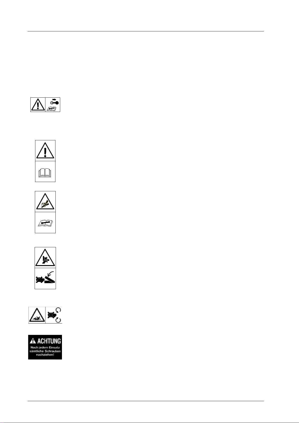
Safety instructions are specified in this chapter that are also affixed as stickers on the im-
plements
Attention!
Danger of injury due to moving parts.
Remove the ignition key before performing maintenance tasks on the im-
plement.
Attention!
Injuries can occur due to improper operation. The implement can be dam-
aged.
Read the operating manual all the way through.
Comply with the safety instructions.
Attention!
Injuries due to fluid escaping under high pressure.
Comply with the instructions in the operating manual.
Attention!
Danger of crushing due to moving parts.
Ne
ver reach into the crushing hazard danger area, if parts are still moving or
can move.
Comply with the instruction in the operating manual.
Attention!
There is an increased risk of accident due to the rotating PTO shaft.
Do not enter the work area of the PTO shaft when it is rotating.
For your own safety do not wear any loose clothing, belts, or any other
loose items. Switch off the implement. Wait until all machine parts have
come to a standstill before converting or servicing the implement.
Attention!
Check all threaded unions prior to using the implement and after using the
implement. Loosened connections must be retightened.
Damage can occur due to loose connections.

Installation
Page 7
3 Installation
Danger!
Severe injury to the operator or third parties occurs.
Switch off the tractor and remove the ignition key before mounting or dis-
mounting the implements.
Note!
Enter the chassis number of the front power lift in section 6, page 23 of this
operating manual.
3.1 Mounting the front power lift
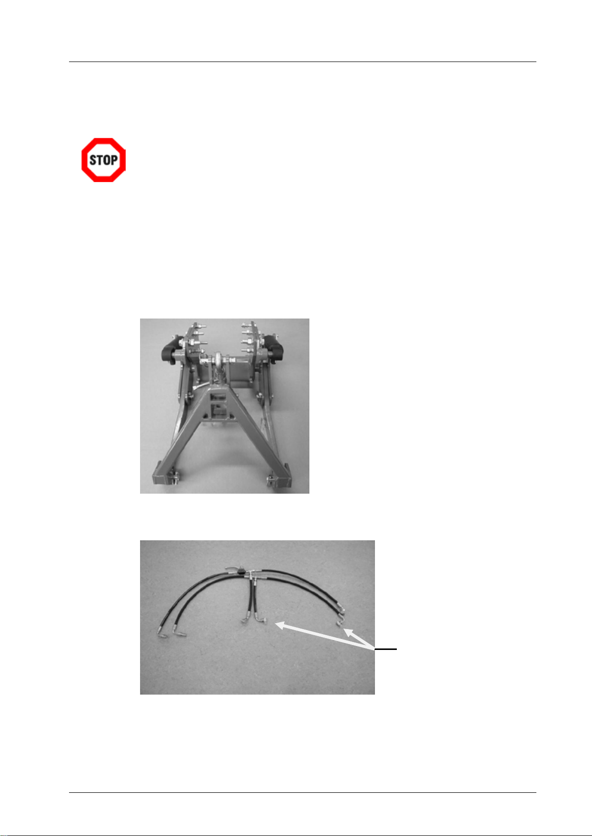
3.1.1 Delivery status
Fig 1: Lift unit with hydraulic cylinders
Fig 2: Hydraulic unit
Cylinder connections

Installation
Page 8
3.1.2 Preparation
Before you mount the front power lift on the frame of the tractor it is necessary to drill 3
tapped holes on each side of the frame. The precise position of the individual bores is
shown in Fig 3.
Fig 3: Mounting bores in the tractor frame
The bore diameter for the A-marked bores is 16 mm, and the bore diameter for the B-
marked bore is 12 mm.
3.1.3 Mounting the front power lift
1. Position the front power lift correctly relative to the tractor.
2. Bolt the front power lift to the tractor frame on both sides with the 2 rear screws
(see Fig 4).
Fig 4: Fastening on the tractor frame
Threaded union

Installation
Page 9
Fig 5: Side plates & upper link holder
3. Fit the cylinders on the side plates.
4. Bring both parts together in the correct position and bolt the side plates to the trac-
tor frame and basic implements with 4 bolts on each side (see Fig 6).
Fig 6: Bolting the side plates
5. Bolt the upper link holder to the tractor frame inside on the front. For use with a
frontloader the upper link must be mounted on the outside.
Fig 7: Installation of the upper link holder
6. Use bolts to fasten the free end of the cylinder to the lift shackle of the basic im-
plement (Fig 8).
Side plates
Upper link holder

Installation
Page 10
7. Secure the bolt with the lock screw.
Fig 8: Cylinder installation with lift shackle
8. Connect the hydraulic hoses to both cylinders and connect the hydraulic hoses to
the tractor's hydraulic lift.
Attention!
Connect the hydraulic hoses in such a manner that the hoses coming from
the stop valve are connected to the bottom of the cylinders.
Fig 9: Installing and connecting the hydraulic hoses
9. Route the hydraulic hoses for the left cylinder directly through and behind the en-
gine (see Fig 10 and 11).
Fig 10: Install the hydraulic hoses, right side
Bolt with lock screw
Stop valve
Hydraulic hose
Questo manuale è adatto per i seguenti modelli
1
Indice
Altri manuali matev Sistema di sollevamento
Manuali Sistema di sollevamento popolari di altre marche

Genie
Genie Z-60/34 Manuale utente

Screen Technics
Screen Technics INTERFIT Vertical Up Lift Manuale utente

Mortuary Lift
Mortuary Lift ULTIMATE 1000 Manuale utente

Custom Equipment
Custom Equipment Hy-Brid 3 Series Manuale di programmazione

Custom Equipment
Custom Equipment Hy-Brid Lifts 2 Series Manuale di programmazione

Hy-Brid Lifts
Hy-Brid Lifts HB-P3.6 Manuale di programmazione