Meletrix ZOOM 65 Manuale utente

ZOOM 65
快速安装指南
BUILD GUIDE
meletrix.cn / meletrix.com
service@meletrix.com
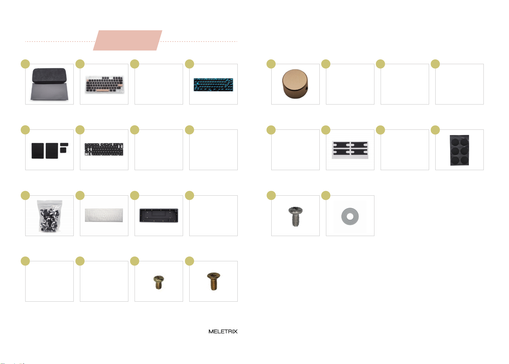
包装内容
Page 1 ZOOM 65 Build Guide Page 2
PACKAGE CONTENT
包装盒
Box & Storage Case
键帽
Keycaps
底壳塡充棉
PORON case foam
PCB底棉
PORON PCB foam
01 02 03 04
旋钮
Knob
旋钮扳手
Knob allen key
钢丝
Stabilizer wire
卫星轴外壳
Stabilizer housing
17 18 19 20
卫星轴轴心
Stabilizer stem
垫片
Stabilizer pads
轴贴
Teflon strips
脚垫
Rubber feet
21 22 23 24
卫星轴螺丝×8
Stabilizer screw×8
Size: M2*4
卫星轴垫圈×8
Stabs washers×8
25 26
PORON 垫片
PORON gaskets
轴下垫
PORON switch foam
夹心棉
PORON plate foam
PCB
0605 07 08
轴体
Switches
PC定位板
PC Plate
上下盖
Case
USB线
Coiled USB cable
1009 11 12
螺丝扳手
Case allen key
铜柱×6
Standoff×6
螺丝×6
Standoffs screws×6
Size: M2*4
螺丝×10
Case screws ×10
Size: M2*5
1413 15 16
61.867
61.867
安装步骤
INSTALLATION STEPS
01
Page 3 ZOOM 65 Build Guide Page 4
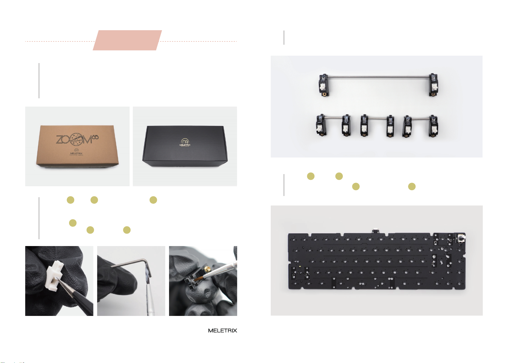
Please make sure to check if the brown or the black packaging box is undamaged. Please
check if the items listed above are not missing. If you’re missing any of the items above
please contact the store you purchased it from before proceeding ahead.
先检查外包装是否有破损,确认后打开包装盒,检查物品是否齐全。如有缺失,请联系您
购买商店的客服。
03 Once lubed, you can start to assemble the stabilizers.
润滑好后,组好卫星轴。
02
Please take out the stabilizer parts. You can holee mod the stabilizers using the provided
teflon strips 23 but it’s not necessary for the included stabilizers. We highly recommend
you to lube the wire 19 and housing 20 for optimal performance and sound. Please
refer to Youtube tutorials on how to properly lube stabilizers.
取出卫星轴 20 和钢丝 19 ,可使用我们提供的轴贴 23 来塡充轴孔内部空间,然后进行润
滑(润滑脂与润轴工具自备)。
04 Take the PORON switch foam 06 and place on the PCB 08 with the shiny side down.
Please make sure the holes lined up like shown in the photo below。
取出PCB 08 和轴下垫 06 ,放置轴下垫(无背胶)到PCB正面。
Page 5 ZOOM 65 Build Guide Page 6
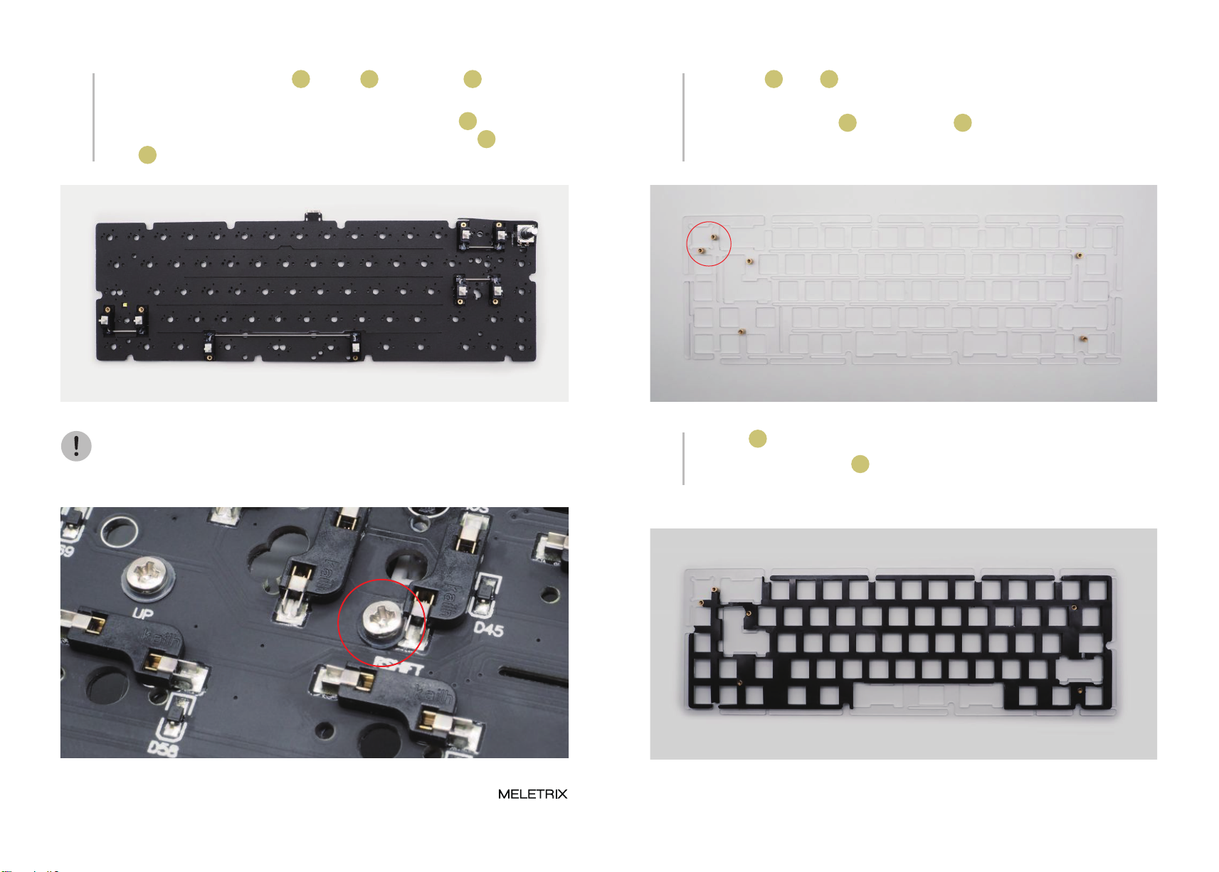
05
Mount the stabilizer on the PCB. You can stick the included the pads 22 under the
stabilizers but it’s not necessary. Please use the included small washers 26 under the
screws 25 of your stabilizers. (Note: The picture show ANSI Layout)
安装卫星轴,根据个人喜好使用垫片 22 ,将垫圈 26 插入卫星轴螺丝 25 ,然后拧好螺丝
固定卫星轴。(注意:图中为ANSI标准配列) 06
Please take out the PC plate 10 and the standoffs 14 . Screw the standoffs on the
backside of the plate (refer to the photo for reference). Only the two standoffs marked by
the red circle are necessary, the rest are optional.
取出PC定位板 10 和铜柱 14 (共六颗),手动拧住铜柱(注意:下图红圈处一定要拧好,不
然旋钮处会塌陷)。
Do not be alarmed if the washer bends and deforms as the screw tightens. The hotswap
sockets are strong enough to absorb the force.
注意该螺丝和轴座会发生干涉,属于正常现象,垫好垫圈直接拧入。 07 Please take out the Plate foam 07 and place it on the backside of the plate, the same
side as the standoffs. Please make sure to align it properly. This foam is optional.
取出夹心棉 07 并覆盖在PCB定位板背面,注意对齐铜柱孔位。

Page 7 ZOOM 65 Build Guide Page 8
Place the PCB on top of the plate & foam combo, with the back of the PCB with the hot
swap sockets facing towards you. Align the standoffs with the corresponding holes and
use the screws 15 to screw the PCB and Plate together.
将PCB背面朝上放在夹心棉和定位板的上方,用螺丝 15 拧入铜柱以连接PCB和定位板。
08
Please take out the PCB foam 04 and take away the transparent film, and place it on the
PCB. Please make sure to align the holes on the foam with the hot swap sockets. This
foam is optional.
取出PCB底棉 04 ,揭开透明的那一面,贴上PCB上,对齐孔位后,揭下蓝色转移膜。
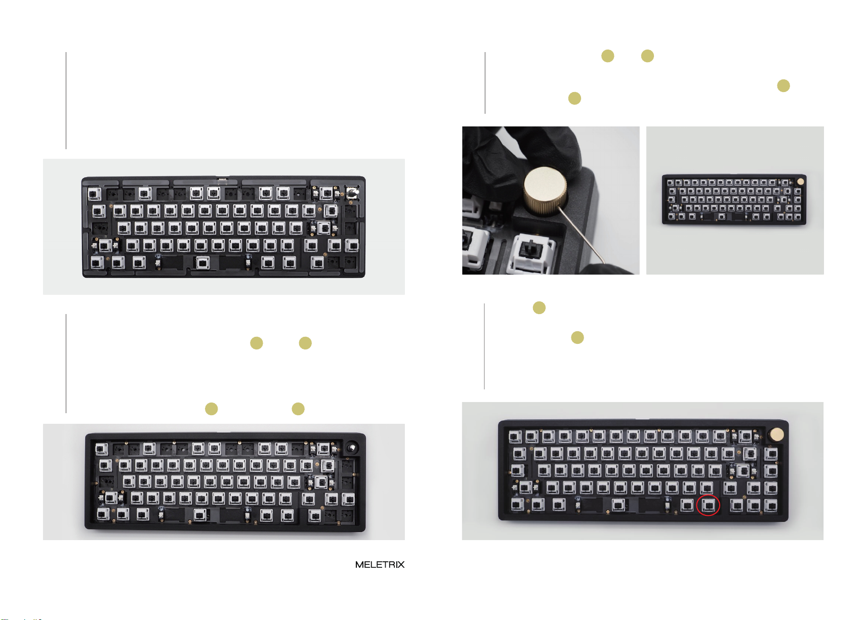
09
10
Please start to install the switches 09 on to the plate. Please make sure to brace the hot
swap socket on the other side of the PCB with your other hand. IMPORTANT: Do not
install switches in the position marked by the red circles right now, you’ll need to access
the screw holes to screw the keyboard case back together. If a switch isn’t going in,
please refer to the tips and tricks section below for help.
If not install the switch correctly, you can use a
switch puller to help you adjust
取出轴体 09 ,并开始安装。装轴的时候需要注意,为了达到软弹的效果,PCB和定位板
都进行了开槽处理。(注意:暂时不装下图红圈处位置的轴体)。
如果轴体没有安装到位,可以使用拔轴器拉拔
开槽处,辅助安装。 Wrong Example: the switch not inserted on
the plate
错误示范:没有卡入定位板。
x

Page 9 ZOOM 65 Build Guide Page 10
11 Please take out the bottom case 11 and place the rubber feet 24 following the picture
below. You can use a screwdriver or a knife to align the feet to the recess in the case.
取出壳体 11 ,装上脚垫 24 。 13 Install gaskets and poron foam 05 on the following the picture below. There are 3 sizes
of gaskets, please use one that matches the recess on the case.
按图示贴好PORON垫片 05。
Please use Allen key 13 to unscrew the top and bottom case (Note: do not rub the frame
of the case with a screwdriver.
使用螺丝扳手 13 拧开上下盖(注意:螺丝刀不要擦到上盖边框)。
14 Place the case foams 03 as shown in the picture below. This foam is optional.
如图分别贴好底壳塡充棉 03 。
12
18
Plug in the USB cable 12 and test all the switches to see if they are working. You can use
VIA to test switches. If a particular switch doesn’t appear to work, please take it out and
make sure the pins are straight. If it still doesn’t work, please contact the store where
you purchased your Zoom65. NOTE: The Fn key, marked by the red circle will not show
up in most keytesters.
插上USB线 12 ,测试所有轴体是否触发,若不触发,首先检查该轴脚是否弯曲,若所有
轴体正常还是无法触发,请联系售后(注意:Fn键无键値,不触发)。
Fn
Page 11 ZOOM 65 Build Guide Page 12
15
Rest the assembled plate + PCB combo on top of the bottom case. Please make sure the
USB port on the PCB aligns with the cutout on the bottom case. Make sure no part of the
PCB is touching the inner walls of the bottom case. The gasket tabs on the plate should
be sitting right on top of the gasket strips on the bottom case. No part of the plate should
be covering any of the screw holes on the bottom case.
将组装好PCB放在底壳上方, 请确保 PCB 上的 USB 端口与底壳上的孔对齐。 确保 PCB
的任何部分都没有接触底壳的内壁,定位板上的垫圈应位于底壳垫圈条的正上方,定位板
不要覆盖底壳上的螺孔。
16
Please place the top case on top of the assembled bottom case from the previous step.
Carefully guide the encoder shaft through the corresponding hole in the top case. The
gap is very precise so you may need to use some force. Pay attention to the to the
positioning of the screw holes to make sure they match up perfectly.On the top case is
properly in place, install the screws 16 using the allen key 13 .
请将上壳放在上一步组装好的底壳之上。 小心地将编码器轴穿过顶壳上的相应孔,因编
码器和上盖孔位之间配合较为精密,需用力插入。注意螺丝孔的位置,确保它们完美匹
配。在上壳正确就位后,使用下图中的螺丝扳手 13 安装螺丝 16 。
装入剩下轴体,然后取出旋钮 17 及螺丝 18 扳手,插入旋钮孔中将旋钮拧紧。
17 Install the remaining switches. Please be careful to not force them in as the hot swap
sockets underneath cannot be braced against the impact. Take out the knob 17 ,and
insert knob allen key 18 into the knob stem and tighten the Jim screw at the side of the
knob. The Jim screw (black in color) is already installed in the knob.

Page 13
19 Install the keycaps. That is all! Congratulations on putting your Zoom65 together!
装上键帽,完成!恭喜你已经成功组装好Zoom 65!
Indice


