GAS PIPING AND GAS PRESSURE REQUIREMENTS
7
All gas piping must be installed
to comply with local codes or, in
the absence of local codes, with
the latest edition of the National
Fuel Gas Code ANSI Z223.1/
NFPA54. Ifflexible hose isused,
it must be listed by a recognized
testing agency.
Danger: Operationof thisheater
on LP gas without an approved
regulator at the supply container
will lead to gas leaks at the
control with possible fire or
explosion.
Caution: The heater and its
individual shutoff valve must be
disconnected from the gas
supply piping system during any
pressuretesting of thatsystemat
test pressures in excess of ˚
PSIG. The heater must be
isolated from the gas supply
piping system by closing its
individual manual shutoff valve
duringany pressuretesting ofthe
gas supply piping system at test
pressures equal to or less than ˚
PSIG. Pressures in excess of ˚
PSIG will cause damage to the
control valve and may cause
damage to the shutoff valve.
Danger: Do not use candles,
matchesor otherignitionsources
when checking for leaks. Fuel
gasesare very flammableand,in
certainconcentrations,explosive.
Checking for leaks with an open
flame may lead to fire or
explosion.
All gas piping must be installed to comply with local codes or, in the
absence of local codes, with the latest edition of the National Fuel Gas
CodeANSI Z223.1/NFPA54. Do not use flexible hose unless the hose
islistedbyarecognizedtestingagency for use with gas and is approved
by the local code authority. Unions in gas lines shall be of the ground
joint type. Compounds used on threaded joints of gas piping must be
resistant to the action of liquefied petroleum gas.
Gas piping must be of sufficient size to provide a minimum natural gas
pressure at the appliance of 7 inches water column or 11 inches for LP
gases. The maximum inlet gas pressure to the heater must not exceed
10.5 inches for natural gas and 13 inches for LP gases. If this heater is
tobe supplied with LP gas(bottled propane or butane) thetankor bottle
supplying the gas must have a regulator that reduces the gas pressure
tobetween 11and 13 inches watercolumn. The control will notoperate
with gas line pressure directly from the tank and may leak gas due to
this excessive pressure.
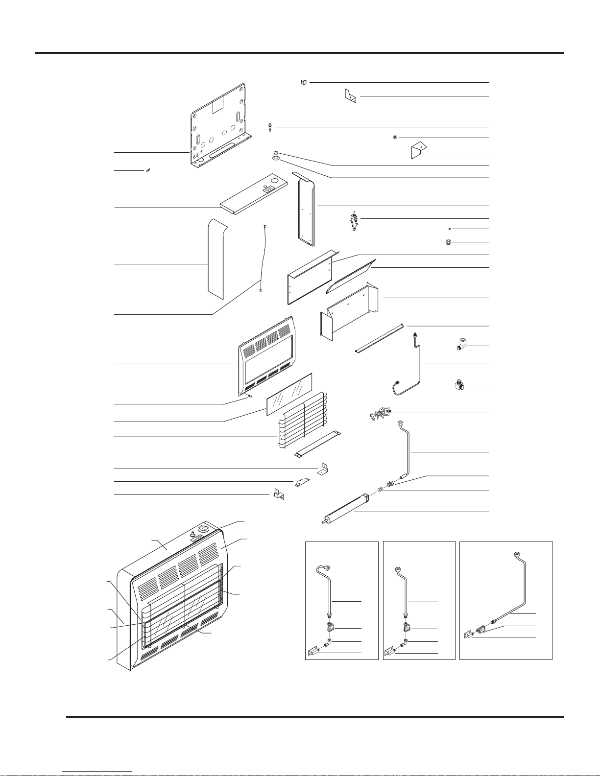
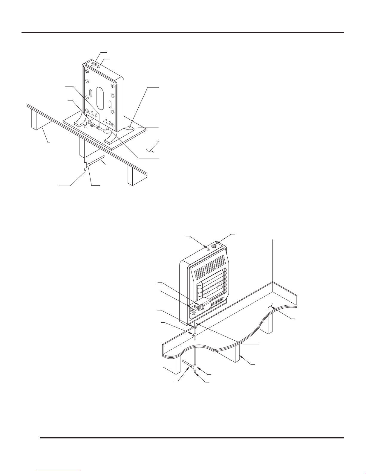
Include a manual shutoff valve and union in the gas line so the heater
maybedisconnectedforservicing. Include asedimenttrap andaplugged
1/8-inchN.P.T. tap in thegas line also. The tap mustbe accessible for a
test gauge connection and should be located somewhere between the
manual shutoff valve and the heater’s 3/8-inch N.P.T. inlet fitting. See
Figures 2 and 3.
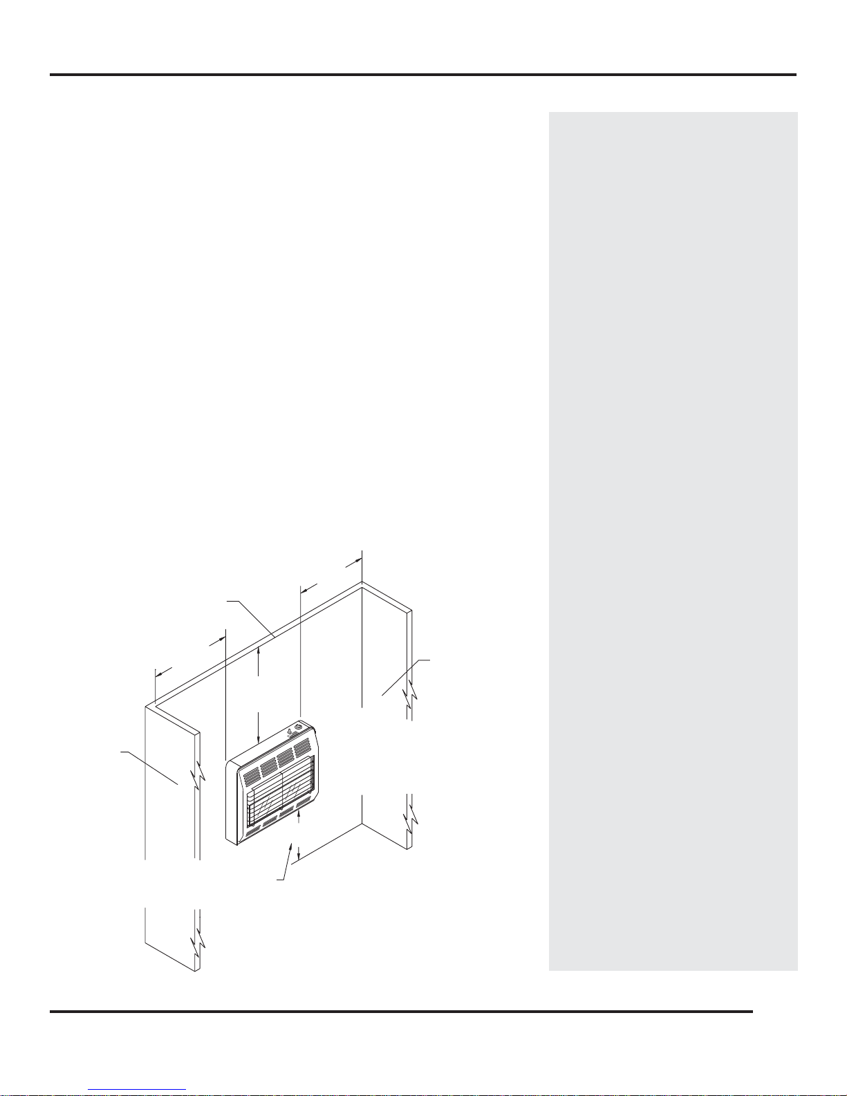
The heater may be mounted on a wall or installed freestanding on an
optionalfloorstand.
A typical gas piping diagram for a freestanding heater installed on a
floor stand is shown by Figure 2.
A typical gas piping diagram for a wall mounted heater is shown by
Figure3.
Use a soap-water solution or a liquid gas leak detector to coat each
jointinthegaslineand look for bubbles which indicate gas leaks. Never
use an open flame when checking for leaks.
Gaseous fuels are highly explosive in certain concentrations and are
very flammable. Any gas leaks in the plumbing supplying gas to this
heater can lead to fire or explosion. REPAIR ALL GAS LEAKS. ALL GAS
LEAKS SHOULD BE REPAIRED BY ACERTIFIED INSTALLER.
53D9013. Rev 1 03/03