
MULTIGUARD Light Manuale utente

multiGuard® Light
Remote control and alarm via GSM
Manual
Ver. 2.02
Profort A/S • Gunnar Clausens Vej 3 DK 8260 Viby J • Tel. +45 70233600 Fax +45 70233601 • E-mail: [email protected] www.profort.dk
INDHOLD
1. SYSTEM DESCRIPTION...................................................2
2. MOUNTING ...................................................................3
Prepare the central unit..................................................3
Install SIM-card ..............................................................3
Electric mounting ...........................................................3
DIP switches for analog inputs.......................................4
Without SIM-card ...........................................................4
3. PREPARE PC ..................................................................5
3.1 Connect PC...............................................................5
3.2 Set-up via USB-RS232 serial converter .....................5
3.3 Find Com-number.....................................................5
4. INSTALLATION OF PC-PROGRAM ..................................6
5. SETTING UP WITH ”QUICK-SETUP” ...............................8
Window 1: Modem.........................................................8
Window 2: Receiver(s)....................................................9
Window 3: Inputs.........................................................10
6. SETTING UP WITH SMS................................................16
Shift PIN-code ..............................................................16
Lost password ..............................................................16
Deactivate password ....................................................16
Setting up receiver(s)....................................................16
Delete receiver .............................................................17
Setting up zone for receiver..........................................17
Approve telephone numbers ........................................17
Change the priority of receivers ...................................17
6.1 SETTING UP DIGITAL INPUTS.....................................18
Set up text....................................................................18
Delete text....................................................................18
Send alarm only if text is entered.................................18
Set up zone for digital input.........................................18
Use input 0 for connection/disconnection ....................18
Set up delayed connection/disconnection.....................18
Set up filter on input ....................................................18
Use input 1 for counting pulses....................................19
Set up different voice message for close open .............19
Delete different voice message for close open .............19
Set up delay on voice message/DTMF ..........................19
Activate 24V.................................................................19
Deactivate 24V.............................................................19
Activate command in text field ....................................19
6.2 SET UP ANALOG INPUTS ...........................................19
Set up zone for analog input ....................................... 20
6.3 SETTING UP OUTPUTS ...............................................20
Activate output in case of alarm.................................. 20
Output follows input ................................................... 20
No activation of outputs.............................................. 21
Outputs show connection/disconnection..................... 21
Delete outputs show connection/disconnection .......... 21
Combine alarm and connection/disconnection ............ 21
Set up macro ............................................................... 21
Delete macro ............................................................... 22
6.4 SYSTEM MESSAGES AND ALARMS ............................22
Send message on connection/disconnection................ 22
Return command ......................................................... 22
Deactivate return command ........................................ 22
Send sabotage and power alarm when the unit is
disconnected ............................................................... 22
Send alarm immediately on power failure ................... 22
Send status message ................................................... 22
Deactivate send status message.................................. 22
Set time in the unit...................................................... 22
Delete time in the unit................................................. 23
Activate automatic timing of
connection/disconnection of the unit........................... 23
Deactivate automatic timing of
connection/disconnection of the unit........................... 23
Text to and from serial port (RS232)............................ 23
Receive text from PLC.................................................. 23
Send text to PLC .......................................................... 23
Data communication with PLC .................................... 23
6.5 COMMANDS FOR SET-UP ..........................................24
7. RECORDING MESSAGES ..............................................30
Duration of voice messages......................................... 30
8. OPERATING.................................................................31
Connect/disconnect the unit........................................ 31
Control relay-outputs................................................... 31
Interrupt further alarms............................................... 31
Requests to the unit .................................................... 32
Activate macros........................................................... 32
Activate macro by call and DTMF: ............................... 32
Restore default settings............................................... 32
9. FREQUENTLY ASKED QUESTIONS ................................33
10. SPECIFICATIONS........................................................36

multiGuard® Light
Remote control and alarm via GSM
Mounting
Ver. 2.02
2
1. SYSTEM DESCRIPTION
The unit is used for controlling relays and
data/alarm- transmission via the GSM-network.
It contains a power supply, a GSM-modem and a
built-in antenna.
The unit can be set up with alarm texts of your
own choice via SMS or via the PC COM-port and
the enclosed ”Quick-setup” program.
Extra equipment:
• External antenna with 2,5 m. cable
(Profort no. 3690003)
• 9V rechargeable battery
(Profort no. 300301)
• Temperature probe
(Profort no. 007995)
• Advanced PC-program “Basic” for many
settings on PC
(Profort no. 900902)
Functions
8 digital inputs
• Make (NC) / break (NO)
• Gnd/24V DC
2 analog inputs
• 0-10 V
• 0-20 mA
• PT100
• Profort temperature probe
• as digital input
Activation of 4relay-outputs
• Activate remotely with SMS and DTMF
• Activate as a function of input (from 10
sec. to 16 min. or follows input).
Forward alarms to max. 25 recipients
• as SMS messages
• as voice call with voice messages
• as voice call with DTMF-tones
• as e-mail (depending on the telephone
company)
Calls 3 times in case of no response (voice
message).
Acknowledgement of alarm by pressing # during
the message (the call list will be interrupted).
Automatic alarm in case of sabotage and power
failure (also in disconnected state).
Back-up in 30 min. in case of power failure with
9V ACCU.
Set clock:
Time based connection/disconnection
Time based status messages
Time registration in the log
Status with intervals of 15 minutes
Status one time per day
Status one time per week (Wednesday)
Commands in the text for inputs
Alarm from 8 zones
Log: 256 records
90 sec. voice memory
Data communication with PLC via RS 232
Variable filter time for inputs: 10 sec. to 30 min.
Delay alarms for 30 sec. when connecting
/disconnecting the unit
Remote control of the unit with macros
System illustration
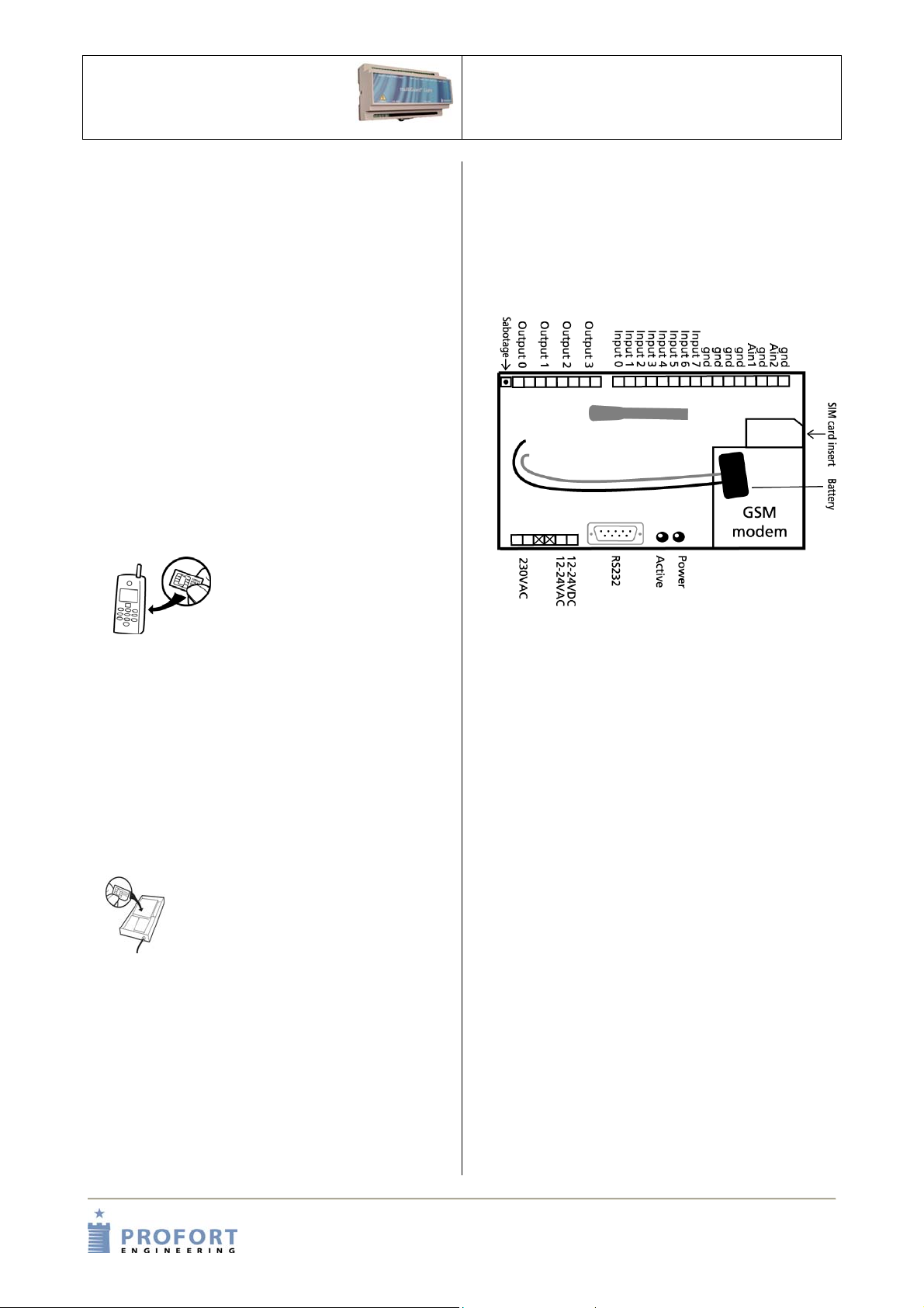
multiGuard® Light
Remote control and alarm via GSM
Mounting
Ver. 2.02
3
2. MOUNTING
The unit has a built-in GSM-modem. All types of
SIM-cards can be used except from 3G cards.
However it is recommended to use a SIM-card
“Pay and go” instead of an ordinary SIM-card
because the latter often has an expiry date after
e.g. 6 months.
Prepare the central unit
1. Lift the front cover of the unit.
The unit must be turned off!
2. Connect all relay-outputs and inputs to
the unit. Use at least 24 AWG – or
stronger if possible.
Install SIM-card
3. Insert the SIM-card
to be used into a
GSM-mobile phone.
4. Check that the SIM-card’s PIN code is set
to 1234 (default for most telephone
companies). If not, set the PIN code to
1234 or deactivate the PIN code.
5. Check if it is possible to call from the
card, and send/receive SMS.
6. Remove the SIM-card fromf the GSM-
mobile phone and insert it into the GSM-
unit.
7. Check that any inputs and
relay-outputs are properly
connected and place the
front cover onto the central
unit again.
8. Connect the central unit to 230 VAC or
12-24 V AC/DC. Wait approx. 10 sec.
while the GSM-modem makes contact to
the GSM-network. When you hear 4
’beeps’ and the red LED lights
continuously for approx. 20 sec. the unit
is ready.
9. Send, if necessary, a SMS with ”1234
OK” to get the GSM signal strength. It
must be higher than 25%.
Electric mounting
The unit can be mounted on a DIN-rail.
1. If the GSM-conditions are bad, replace
the internal antenna by an external
antenna.
2. Mount, if necessary, 9V rechargeable
battery.
3. Connect outputs:
Relay-outputs are potential free relay
contacts that break (NO) or make (NC)
by means of instructions to the unit. As
default all relay-outputs are open.
4. Connect digital inputs:
Digital inputs are optocouplers. The
inputs are activated by 0V default (gnd)
or 24 VDC on inputs (can be changed in
the set-up program). If the supply is
removed the inputs will deactivate. In
both cases an alarm can be sent from
the central unit.
NB! Input 0 can also be used for
activating/deactivating the unit (toggle
switch or bell switch).
Input 1 can be used for counting pulses.
GND or 24V on inputs, selected as
option in the PC-software.

multiGuard® Light
Remote control and alarm via GSM
Mounting
Ver. 2.02
4
5. Connect analog inputs:
As default the analog inputs function as
ordinary digital inputs (all Dip - switches
off). If the analog inputs are to be
adapted to standard equipment:
0-10VDC, 0-20 mA or PT100 probe, the
Dip-switches in the GSM-modem must
be adjusted as illustrated below.
DIP switches for analog inputs
Digital: Dip-switch 1-4 off
0-10VDC: Dip-switch nr. 1 on (others off)
0-20mA: Dip switch nr. 2 on (others off)
PT100: Dip switch nr. 3 on (others off)
Profort probes: Dip switch nr. 4 on (others off)
Each analog input has 4 Dip-switches.
Equipment and probes must be connected
between gnd and Ain1 or between gnd and
Ain2.
Without SIM-card
If the unit is connected without a SIM-card it is
important to remove the front cover. Otherwise
the unit will try to reach the GSM-net and any
progamming from a PC will be blocked.

multiGuard® Light
Remote control and alarm via GSM
Prepare PC
Ver. 2.02
5
3. PREPARE PC
Start by connecting the serial converter and
finding the COM-port number on the PC.
3.1 Connect PC
1. Connect the COM-port output of the unit
to COM1 or the USB plug on the PC. Use
a 9 pole serial cable or a USB to RS 232
serial converter. The illustration below
shows the connections used in a RS232
cable.
Minimum requirements, PC:
Windows 95, 32 Mbyte RAM
Monitor, 800x600 screen
COM-port or USB-port
3.2 Set-up via USB-RS232 serial
converter
When the USB cable is connected to the USB
plug on the PC Windows provides the PC with a
COM-number. A PC can have more than one
COM-port, and the actual COM-number
provided by Windows depends on which COM-
port is used for setting up the unit. Therefore it is
necessary to check which COM-number
Windows has given to the selected COM-port.
1. Install the driver enclosed with the USB-
converter and follow the instructions for
this product.
2. Connect the USB-cable to the USB-plug
on the PC.
Notice that the next time you connect the
USB-cable to either the same or another
COM-port the given COM-number can have
been changed.
3.3 Find Com-number
3. Select the menu START on your PC.
4. Select Control panel > System.
5. Select Hardware > and the first button
just below.
6. Select Ports.

multiGuard® Light
Remote control and alarm via GSM
Prepare PC
Ver. 2.02
6
7. Read the USB-to-Serial COM-Port.
4. INSTALLATION OF PC-PROGRAM
When the COM-no. is identified start the PC-
program for setting up the unit.
Install the set-up program on the PC:
1. Check that the COM-port output of the
unit is connected to COM1 or the USB
plug on your PC.
2. Insert CD-ROM in PC and click OK.
Windows suggests to install the setup-program
in C:\Programmes\Profort
To change this location, press Change Directory
and select the required folder.
3. Click the button in the upper left corner
in order to start the installation.
The installation runs automatically and
takes about 20 sec.
4. Start the setup-program on the PC. If the
text ”Version conflict” appears select
the latest version.
5. Enter the product key in the window
’Product key’ which is automatically
displayed: The product key is written on
the cover of the CD-ROM.
If you have entered a product key to access
Quick-setup the screen below will be displayed:

multiGuard® Light
Remote control and alarm via GSM
Installation of PC-program
Ver. 2.02
7
6. Select the number of the COM-port to
which the unit is connected. If a correct
COM-port is selected the text
”Connection to multiGuard” in the
bottom
left corner will appear.
NB! If the text ”No Connection” appears
either a wrong COM-port is selected, the
unit is turned off or the RS232 cable is
defect.
If the text ’Connection to multiGuard’ doesn’t
appear, you have to check if
the correct COM-port has been selected.
7. Click the ‘Back’ button. Select
Communication port, only available
communications ports are listed.
8. Click the ’Next’ button and you will be
guided step by step through 4 setting
windows (see Setting up with Quick-
setup).

multiGuard® Light
Remote control and alarm via GSM
Setting up with
Quick set-up
Ver. 2.02
8
5. SETTING UP WITH ”QUICK-SETUP”
Start Quick set-up on the PC and follow the set-up instructions through the 4 windows. The settings will
be stored in unit’s ’flash memory’ and can be recovered in case of power failure. If the unit is coded
without a SIM-card the front cover must be removed.
Window 1: Modem
Present password: The password of the unit. When starting set-up the default password 1234 must be
applied. Remember that the PIN-code of the SIM-card in the unit also has to be
1234 when starting set-up.
GSM-number: Here the telephone number of the SIM-card in the unit is entered (optional unless the
clock-function is applied).
New password: Only numbers – not letters (4 digits). Here a new password, if required, is entered.
The PIN-code of the SIM-card will be changed similarly. If the password must be
deactivated the new password must be: 0000.
ID: Numbers or letters. Here an ID of the unit (max. 32 digits), if required, is entered.
Can be sent with all alarms.
NB! The password is applied for sending commands to the unit. The ID is transmitted
from the unit in case of alarm. If no ID is entered the password will also be the ID.

multiGuard® Light
Remote control and alarm via GSM
Setting up with
Quick set-up
Ver. 2.02
9
Window 2: Receiver(s)
It is possible to encode max. 25 receivers/ telephone numbers.
Forward alarms
Alarm messages can be forwarded as SMS, Voice, DTMF or E-mail. If you wish to receive both a SMS and
an analog voice message it is necessary to set up the same telephone number twice. A phone number can
be of max. 15 digits. An E-mail address can be of max. 48 characters.
Zone
In the field ’Zone’ (optional) is indicated whether all alarm messages are to be forwarded to the entered
telephone number or if this actual telephone number is to be called only in case of alarm from a specific
zone (0-7). Only one zone can be entered. If the same telephone number is to be called in case of alarm
from e.g. 2 zones the actual telephone number must be entered twice. If the field ’Zone’ is empty, alarm
from all zones will be received. The field ‘Zone’ disappears when the option ‘Approve’ is active.
Approve telephone numbers
If one or more telephone numbers are selected in the field ‘Approve’ the unit accepts SMS and analog
calls only from these numbers.
NB!: If the approved telephone number is not correct it is necessary to connect a cable in order to contact
the unit.
multiGuard® Light
Remote control and alarm via GSM
Setting up with
Quick set-up
Ver. 2.02
10
Window 3: Inputs
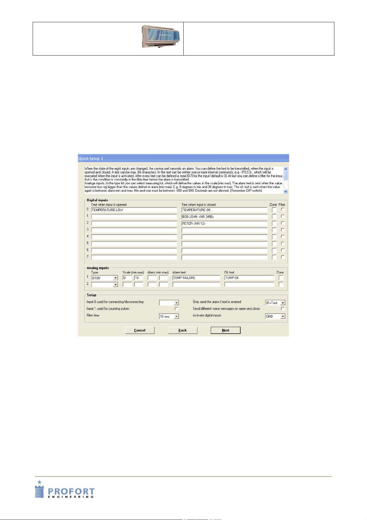
if the unit is not to be set up with user defined texts the unit will send the following standard messages in
case of alarm:
• S0 .. S7: Make/close on input 0 to 7.
• B0 .. B7: Break/open on input 0 to 7..
If the unit is to be set up with user defined texts these can be encoded by means of the enclosed program
”Quick-setup”.
Enter F1 in order to access the help menu for setting op the unit.
Text for inputs
In the window ’Inputs’ the text (max. 64 characters) to be displayed when an input changes position
is entered.
It is not necessary to enter a text also for closed position. That is if the activated relay is within a distance
of where it is possible to go inspect the problem. But it can be helpful if you are far away from the
activated relay and need a feedback on whether e.g. an irrigation plant has been inspected and again
functions normally.
If an alarm is to be sent only from the inputs which have a text, select either ‘ID + Text’ (return ID an
alarm text) or ‘Text’ (return only alarm text) in the field ‘Only send the alarm if text is entered’. Thereby
empty inputs will be filtered.
If ’Only send the alarm if text is entered’ is empty all alarms will be sent whether a text is entered or not.
Indice
Altri manuali MULTIGUARD Telecomando


