Myson X 100 TH Manuale utente

MYSON
X 100 TH
www.myson.se
UK User´s manual
SE Manual
NO Håndbok
DK Manual
FI Käyttöohje
PL

DESIGNATION
MYSON X 100 TH are designed for ventilation
of domestic and similar premises (apartments,
ofces, stores, garages, bathrooms, toilets and
other rooms.
SET OF SUPPLY
The following articles are included in the supplied
set:
Fan: 1 pc.
Front: 3 pcs.: black, red, grey
Backdraught shutter: 1 pc.
User’s manual
Packing box
Screws: 4 pcs.
BASIC SPECIFICATIONS
The fans are designed for operation from AC
power supply with voltage of 220–240 V and
frequency of 50 Hz.
Fans are designed for operation at air temperature
max 40°C.
SAFETY REQUIREMENTS
The fan MYSON X 100 TH complies with the requi-
rements according to the EU norms and directives,
to the relevant EU-Low Voltage Equipment Direc-
tives, EU-Directives on Electromagnetic Compati-
bility.Level of protection from access to hazardous
parts and waterproof:
IP24
Connection of a fan that does not have a captive
power cable must be carried out by a qualied
electrician. The same applies to the replacement of
a fans power cable. Children or people with limited
physical or mental capabilities must not use the
equipment without instructions on how to use it
safely. The fan must not be used outside the stated
range of operating temperatures or in places where
there are aggressive mixtures of gases.
ATTENTION!
Fan operation when restirictions, being able to
damage or jamm blades of operation wheel, are in
owing part of case, is prohibited. Precautions must
be taken to avoid the black-ow of gases into the
room from the open ue of gas or other appliances.
UK
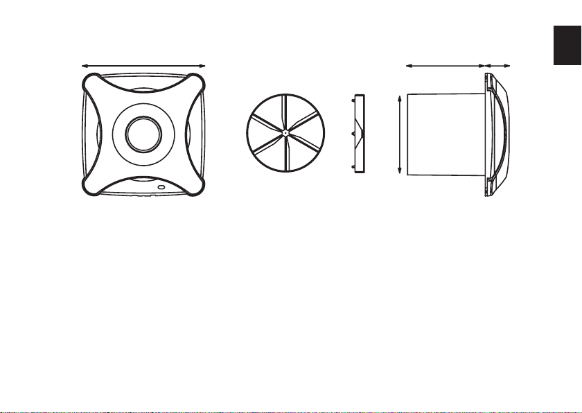
Model Description
X 100 TH Adjustable humidity sensor 60–95 % RH
with adjustable timer with run-on-time
2–30 min, backdraught shutter.
30
100
96151
30
100
96151
30
100
96151
UK

PREPARATION TO DEVICE OPERATION.
Attention! All maintenance works and connection
of fans are to be performed only after switching
off mains. Connection of fans to electric power
supply must be performed only through switch
with actuation length not less than 3 mm at all
poles. Direction of air-charging is to comply with
directionof arrow on the fan case.
If necessary, ensure conditions to prevent free
access to impeller and current-carrying parts of
fan by protective means from side of outcome
(ventilation grille, protective cowl, backdraught
shutter and so on). Connection of fans to electric
power supply is shown in Fig. 1 and 2.
OPERATIONS OF CONNECTION TO POWER
SUPPLY
Remove protective grid and cover, Fig. 1. Pass
power supply cords through a hole 3 (having cut a
thin plastic pierce on the spot of opening before-
hand). Smooth out wire rags at length 7-8 mm to
clamp terminals 4 agaist stop to the metal part of
the clamp and tighten them with screws. Fix cords
with the help of clip 2. Reinstall cover and protec-
tive grid back.
For fans without switch, it is advisable to install
powersupply switch on xed power supply wiring.
Diagram of connection of fan to xed power supply
wiring is shown in Fig. 2.
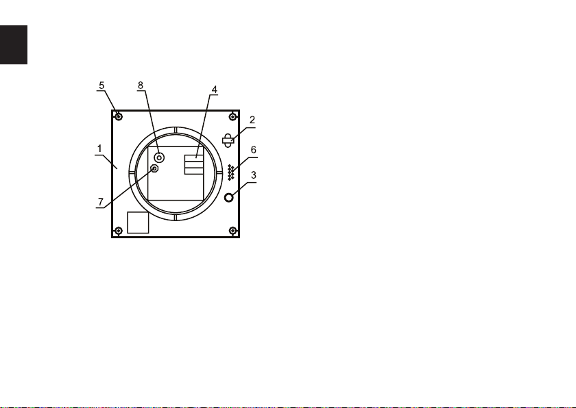
UK

Myson X 100 TH with removed cover
1 - housing
2 - clip of power supply cords
3 - holes for power supply cords
4 - clamp terminal
5 - holes for fan mounting
6 - cable securing pins
7 - adjustable timer with run-on-time 2–30 min
8 - adjustable humidity sensor 60–95 % RH
Fig 1
UK

Fan equipped with timer / timer with humidity relay and wthout built-in switch.
Fig 2
Fan switch off delay time is adjustable within the range of approx. 2 to 30 minutes.
Time can be regulated by potentiometer T. Delay increase direction is clockwise, and
delay decrease is anticlockwise). Fans supplied with timer and humidity relay are
turning on by certain humidity level. (50-90%) and are regulated by potentiometer H
by rotaiton clockwise to increase and anticlockwise to decrease level during the time,
adjusted by timer.
Attention!
Diagram of timer is situated under circuit potential. It is forbidden to regulate timer’s
delay time unless fan is switched off the mains. Diagram in Fig. 10 shows connection
of lighting lamp to fan’s timer controlled by single switch (S is an outer switch).
When lightning lamp is off, fan works during the time, adjusted by timer.
UK

AVSEDD ANVÄNDNING
MYSON X 100 TH är konstruerad för ventilation av
bostadsutrymmen och liknande lokaler (lägenheter,
kontor, förråd, garage, badrum, toaletter etc).
LEVERANSOMFATTNING
Följande komponenter ingår i leveransen:
Fläkt: 1 st
Front: 3 st: svart, röd, grå
Kallrasskydd: 1 st
Användarhandledning
Förpackning
Skruvar: 4 st
TEKNISKA DATA
Fläktarna är konstruerade för drift med nätspän-
ning, 220–240 V / 50 Hz
Fläktarna är konstruerade för drift vid lufttempera-
tur max 40°C
SÄKERHETSKRAV
MYSON X 100 TH uppfyller kraven i EUs Lågspän-
ningsdirektiv och EMC-direktiv. Beröringsskydd
och skyddsgrad:
IP24
Anslutning av äktar utan fast monterad kabel,
samt byte av kabel, får endast utföras av behörig
elektriker. Barn eller personer med begränsad
fysisk eller mental förmåga får inte använda ap-
paraten utan instruktioner om hur den används på
ett säkert sätt. Drift av äkten utanför angivet drifts-
temperaturområde eller i lokaler där det förekom-
mer aggressiva gasblandningar är förbjuden.
OBS!
Drift av äkten i miljö där det kan komma in främ-
mande objekt i luftkanalen som kan skada eller
blockera äkthjulets blad är förbjuden. Undvik att
installera äkten så att den kan orsaka backöde
till rummet av förbränningsgaser från gasbrännare
eller liknande apparater.
SE

Beteckning Beskrivning
X 100 TH Justerbar fuktsensor (60–95 % RH),
timer med justerbar eftergångstid på
2–30 minuter, kallrasskydd.
30
100
96151
30
100
96151
30
100
96151
SE

FÖRBEREDELSER FÖR DRIFT
OBS!
Anslutning och underhåll får ske endast när äkten
är skild från matningsnätet. Fläktar får anslutas till
matningsnätet endast via en allpolig brytare med
ett kontaktavstånd på minst 3 mm hos samtliga
poler. Fläkten skall installeras så att strömningsrikt-
ningen överensstämmer med pilen på kapslingen.
Vid behov, hindra åtkomst till äkthjul och elek-
triska komponenter från trycksidan med hjälp av
äktgaller, kåpa, kallrasskydd e.dyl. Anslutning av
äktar till matningsnätet illustreras av gur 1 och 2.
ANSLUTNING TILL MATNINGSNÄTET
Ta bort äktgaller och kåpa, se gur 1. För in mat-
ningskabeln genom hålet 3. Hålet är förstansat och
täckt med tunn plast som penetreras före installa-
tion. Skala ledarändarna 7-8 mm och för in dem så
långt det går i plinten 4. Dra åt plintskruvarna. Fix-
era kabeländen med kabelklämman 2. Sätt tillbaka
kåpa och äktgaller.
För äktar utan egen brytare är det lämpligt att
göra en fast brytarinstallation. Kopplingsscheman
för fast installation av äktmatning nns i gur 2.
SE
Myson X 100 TH med kåpan borttagen
1 - Fläkthus
2 - Kabelklämma för matningskabel
3 - Hål för matningskabel
4 - Anslutningsplint
5 - Fästhål för äkt
6 - Kabelxerare
7 - Timer med justerbar eftergångstid
8 - Justerbar fuktsensor
Fig 1
SE
Questo manuale è adatto per i seguenti modelli
1
Indice
Lingue:
Altri manuali Myson Fan


