
Nagel FOLDNAK 4 Manuale utente

English
FO
LDNAK 4 / 6 / 8
User Manual

2
1 Contents
1 Contents
2 Description of function
3 Safety rules
4 Installation
4.1 Slat conveyor
5 Preparation
5.1 Stapler heads / Stapler head distance
5.2 Staples
5.3 Inserting staples
6 Operation
6.1 Control panel
6.2 Magazine control
6.3 Staple error control
6.4 Equipment control
6.5 Stapling brochures
6.5.1 Formats / Number of sheets
6.5.2 Adjustment of the side stop
6.5.3 Adjustment of the rear stop
6.5.4 Adjustment of trigger
6.5.5 Triggering by hand
6.5.6 Counter
6.5.7 Adjustment of the slat conveyor
6.5.8 Stapling
6.6 Stapling blocks
6.6.1 Formats / Number of sheets
6.6.2 Block stapling with the Foldnak 8
6.6.3 Block stapling with Foldnak 6 and Foldnak 4
7 Accessories
7.1 Staples heads, staplers
7.2 Vertical vibrator
7.3 Coupling to assembling machines
7.4 Trimmer
8 Service
8.1 Possible malfunctions
8.2 Change the driver
8.3 Stapler head care and malfunctions
8.4 Cleaning rollers
8.5 Rotating the machine by hand
9 Technical data
10 Conformity statement

3
2 Description of function
1. Control panel with
main switch
2. Guard plate
•The machine can only
be operated with a
closed guard plate
3. Slat conveyor
4. Turning handle
5. Opening to decouple the
folding knife.
6. Protective cover
•The machine can only
be operated with a
closed protective cover

4
Dear customer,
Thank you for having decided upon our
stapling folding machine. With the
purchase of this quality product you
have made a good choice.
Please read these user instructions
carefully before using the machine and
follow the security rules.
The numbers in brackets in the text
relate to the figures.
3 Safety rules
•Only carry out repairs with original
NAGEL spare parts.
•Only carry out repairs after
disconnecting from the mains
electricity supply.
•Repairs and work upon electric
appliances may only be carried out
by trained tradesmen.
•Removal of safety equipment and
casing and operation with damage
that affects safety is forbidden (e.g.
damaged electricity cables,
covering).
•Use the machine exclusively to staple
documents out of paper and
cardboard.
•Lay out the electricity cable in such a
way that it does not form any kinks.
•Work place of the operator: in front
of the machine.
•Only erect the machine in a dry
room.
4 Installation
•Loosen the restraining straps of the
wooden box.
•Remove the wooden box.
•Strip the packing foil to the bottom.
•Loosen the restraining screws
between the Foldnak and the palette.
•Lift the machine from the palette and
place the machine on a solid and
level surface.

5
4.1 Slat conveyor
The slat conveyor (fig001, 3) (option
with Foldnak 4) is folded upright for
transport and locked with a hook.
Raising the hook unlocks it and swings
it into an approximately horizontal
position. In this position the rod (11) is
guided into the hole of the foot stand as
a prop. The rear collecting plate (13) is
then hung downwards at an angle.
The axle and both wheels (10) are
accessories. They must be pre-mounted
with the set collars, which are also
accessories, so that both wheels are
exactly over the green conveyor belts
when the axle lays in the long vertical
slits of both axle brackets (12).
These axle brackets on both sides of the
slat conveyor are to be swung into a
vertical position and, after loosening
the knurled screws, then secured. When
not in use, the axle with the transport
wheels can be taken off, the axle
brackets folded towards the bottom and
the slat conveyor can be folded upright
and locked in order to save space.

6
5 Preparation
5.1 Stapler heads / Stapler head
distance
Foldnak stapling-folding machines are
delivered with two stapler heads as
standard. They can be operated with up
to four stapler heads. The possible
stapler head positions are:
Type Distances in mm
Foldnak 8 30 x 50 x 80 x 50 x 30
Foldnak 6 30 x 50 x 80 x 50 x 30
Foldnak 4 50 x 80 x 50
The stapler heads can be adjusted in the
previously given positions. For this, the
screws (21) behind the stapler head
batten (22) must be unscrewed with the
supplied hexagonal spanner, the stapler
head must be put into the desired
position with the spigots and screwed
tightly again.
The driver (20) is re-set as described in
Chap 8.2. By adjusting the stapler
heads and simultaneous adjustment of
the side stops, the position of the
staples in the paper can be altered. Care
must be taken that the stapler heads are
not placed over the side stops,
especially when the stapler heads are
used in the outer positions. Finally,
plug the contact cable (19) onto the
contact bank (18).

7
5.2 Staples
Foldnak stapling-folding machines use
the following Nagel-staples:
•26/6
26 = Wire guage
6 = Shank length in mm
for 2 up to ca. 20 sheets
•26/8 S
26 = Wire guage
8 = Shank length in mm
S = Steel wire
for 15 up to ca. 40 pages
•Ri 26/6
Ri = Ring staples
26 = Wire guage
6 = Shank length in mm
for 2 up to ca. 20 sheets
Only use original Nagel staples. They
are made with special precision and
therefore guarantee problem free and
accurate function.
We can only honour the staple head
guarantee when Nagel staples are used.
5.3 Inserting staples
In order to insert staples, first of all the
staple slide (26) is to be pulled back
with the index finger on the underside
of the stapler head magazine until it
engages.
Then swing back the magazine cover.
Insert the staples in this position. The
magazine holds a stick of 210 staples or
ring staples. When changing staples,
check that no staples of the old type
have been left in the magazine. Then
the magazine cover is to be closed and
the staple slide guided forwarded with
the thumb and index finger. Do not let
it shoot forward too quickly otherwise
the staple stick breaks.

8
6 Operation
6.1 Control panel
The Foldnak 8 control panel is laid out
as follows:
(36) Red signal light. It illuminates
when the staples are finished or
jammed. The machine can not trigger
any more.
(35) On - off switch.
(34) Numbers counter with reset button.
(33) Service switch wide. In position 1
it serves as a brake lifting switch for the
stroke motor brake.
(32) Service switch narrow. It serves as
manual release. The photo-cell must be
pushed out for this.
(31) Folding rollers on - off. The rollers
must be switched off for block stapling.
(30) Block stapling switch. Switches on
the block stapling stop in position 1.
(29) Rotary button for the slat
conveyor. Controls the separation of the
brochures on the slat conveyor (see
Chap. 6.5.7, only Foldnak 8).
Foldnak 6 und Foldnak 4 do not have
the switches (30) and (29).
6.2 Magazine control
The Foldnak is fitted with a magazine
control. When there are not any more
staples in the staple magazine, the
machine does not trigger. This state is
indicated by illumination of the red
signal lights (36) on the control panel if
the contact cable (fig003, 19) has been
fitted.

9
6.3 Staple error control
The foldnak is equipped with a staple
error control. The staple error control
stops the machine triggering when there
is a staple jam in the stapler head. In
this condition the driver jumps out of
its suspension and touches the spiral
contact (fig003, 15). This causes the red
signal light to illuminate. Then the
driver has to be hung again after any
stapler remnants have been removed
from the stapler head (see chap. 8.2 and
8.3).
6.4 Equipment control
The Foldnak is equipped with an
equipment control. It stops the stroke
triggering when the paper has not been
laid in correctly. The equipment control
only works when the trigger has been
correctly adjusted (see chap. 6.5.4).
6.5 Stapling brochures
6.5.1 Formats / Number of sheets
Paper formats from 140 x 210 mm to
325 x 450 mm can be processed in the
Foldnak stapling folding maching. This
includes for instance DIN A3, A4 and
A5.
The number of sheets which can be
processed in a brochure is dependant
upon the thickness of the paper and the
cover. Dependant upon the paper
quality ca. 30 sheets of 70g paper or 25
sheets of 80g paper can be processed
for brochures with 120 or 100 pages.
When a cardboard cover is used then
the number of sheets is to be reduced
accordingly.
1
6.5.2 Adjustment of the side stop
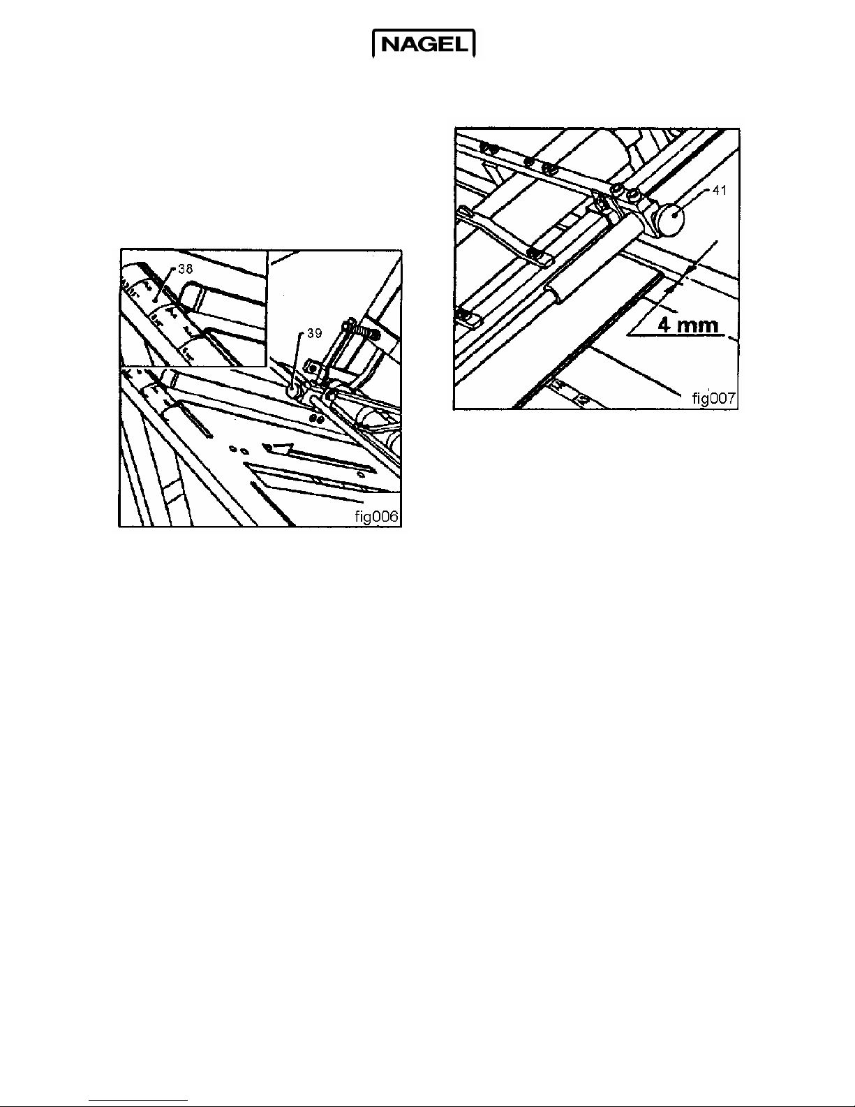
First of all adjust the side stop with the
assistance of the scale (38) on the green
table plate. To do this the knurled screw
(39) is opened and the stop moved to
the side.
After correct adjustment the knurled
screw is again tightened.
Then adjust the right stop.
To do this, insert a sheet of the paper to
be processed and, after opening the
knurled screw (41), the right stop is
then brought flush to the sheet. From
there, move ca. 4 mm to the right and
secure the side stop in this position.
This guarantees that the jogging
movement which has been built into the
right side stop, and is ca. 4 mm, lines up
the staples smoothly.
Questo manuale è adatto per i seguenti modelli
2
Indice
Altri manuali Nagel Macchina piegatrice


