Nasum A5 Pro Series Manuale utente
English
Deutsche
Français
Italiano
Español

Before Using the laser engraving, please read this safety guide carefully, it mentions situations that require special
attention and includes warnings of unsafe practices that can cause damage to your property or even endanger your
personal safety.
1. This product is a laser engraver system components, must be installed in other manufacturers of laser engraver for
use.And the product belongs to Class 4 laser products, the laser system itself must meet the requirements of IEC 60825-1
latest version, otherwise the product is prohibited to be used.
2. Your laser engraver shall have a protective housing which, when in place, prevents human access to laser radiation.
3. If a protective housing is equipped with an access panel which provides "walk-in" access then:
a)means shall be provided so that any person inside the protective housing can prevent activation of a laser hazard that is
equivalent to Class 3B or Class 4.
b)a warning device shall be situated so as to provide adequate warning of emission of laser radiation equivalent to Class
3R in the wavelength range below 400 nm and above 700 nm, or of laser radiation equivalent to Class 3B or Class 4 to any
person who might be within the protective housing.
c)where “walk-in” access during operation is intended or reasonably foreseeable, emission of laser radiation that is
equivalent to Class 3B or Class 4 while someone is present inside the protective housing of a Class 1, Class 2, or Class 3R
product shall be prevented by engineering means.
NOTE Methods to prevent human access to radiation when persons are inside the protective housing can include
pressure sensitive floor mats, infrared detectors, etc.
Part 1: Security Statment Before Installation

4. The laser itself has a protective cover, the protective cover is fastened by screws. When the laser is installed on the laser
engraver, the protective cover should be checked to be reliably locked, and can not be removed in the energized state.
5. The housing of the laser engraver should have an interlock function. When the housing is opened or removed, the laser
can be automatically turned off.
6. The laser engraver should have an emergency stop button, which can immediately stop the output of the laser when
pressed under unexpected circumstances.
7. The laser engraver should have a reset button, which can resume work under the condition of confirming safety after
lifting the interlock or emergency stop.
8. Laser engraver should use physical keys, dongle, password system and other ways to manage and control, to prevent
personnel without security training operation of this kind of equipment.
9. On the laser engraver any window or channel that can actively observe or passively receive the laser radiation should be
set up warning marks.
10. If the laser burns the skin or eyes, please go to a nearby hospital for examination and treatment immediately

Laser Light can damage the human eyes and skin. Do not expose the eye or skin to laser light directly. This Laser product
has an optical lens and emits a collimated laser beam. The light from this product, both direct and reflected, is very
harmful as it can propagate a long distance while maintaining high optical density. When handling the product, wear
appropriate safety glasses (OD5+) to protect eyes from laser light including reflected and stray light. The reflected and
stray light spilling into an unintended area should be attenuated and/or absorbed.
2.1 Laser safety
We installed a laser shield on the laser, the shield can largely filter out the diffuse reflection of the laser spot.However,
when using laser engraving machine, it is recommended that you wear laser protective glasses. Avoid skin exposure to
type 4 laser beams, especially at close range.Teenagers must have parental supervision in the process of using it.Do not
touch the laser engraving module when the machine is on.
2.2 Fire Safety
Because cutting burns off the substrate, a high-intensity laser beam generates extremely high temperatures and a lot of
heat.Certain materials can catch fire during cutting, creating gases and fumes inside the equipment.A small flame usually
appears here when a laser beam hits the material.It will move with the laser and will not stay lit when the laser passes
by.Please do not leave the machine unattended during the carving process.After use, be sure to clean up debris, debris
and flammable materials in the laser cutting machine.Keep a working fire extinguisher nearby at all times.Smoke or air
pollutant safety. When laser engraving machines are used, smoke, vapour, particles, and potentially highly toxic materials
(plastics and other combustible materials) are produced from the material.These fumes or air pollutants can be hazardous
to health.
Part 2:User Security Statement

2.3 Material safety
Do not engrave materials with unknown properties.Materials Recommended:Wood, bamboo, leather, plastic, fabric,
paper, opaque acrylic, glass.Materials not recommended:Metal, precious stones, transparent materials, reflective materials
etc.
2.4 Use Safety
Use the engraver only in horizontal position and ensure that it has been securely fixed to prevent fires caused by
accidental shifting or dropping from the workbench during work.It is forbidden to point the laser to people, animals or
any combustible object, whether it is in working condition or not.
2.5 Powersafety
Topreventaccidentaldisasterssuchasfireandelectricshock,the
A5ProLaserEngraverprovidesapoweradapterwitha
groundwire.Plugthepowerplugintothepowersocketwithaground wirewhenusing theLaserEngraver.
2.6 Environment safety
Please ensure the workplace must be cleared while assembling engraving and cutting no flammable or explosive
materials surrouding the equitment. Have to set a metal plank under the bottom while engraving or cutting.

Part 3: Disclaimer and warning
Thisproductisnotatoyandisnotsuitableforpeopleunder15yearsofage.Donotallowchildrentotouchthelaser
Module.Pleasebecarefulwhenoperatinginsceneswithchildren.
Thisproductisalaser module,We reserve the right to update this disclaimer and safety
instructions..reservestherighttoupdatethisDisclaimerandSafeOperationGuidelines.
Pleasebesuretoreadthisdocumentcarefullybeforeusingtheproducttounderstandyourlegalrights,responsibilitiesa
ndsafetyinstructions.Otherwise,itmaybringpropertyloss,safetyaccidentandhiddendangerofpersonalsafety.Once
youusethisproduct,youshallbedeemedtohaveunderstood,acceptedandacceptedalltermsandcontentsofthisdoc
ument.Userundertakestoberesponsibleforhisorheractionsandallconsequencesarisingtherefrom.Useragreestous
etheProductonlyforlegitimatepurposesandagreestotheentiretermsandcontentsofthisdocumentandanyrelevan
tpoliciesorguidelinesthat mayestablish.
You understand and agree that may not be able to provide you with the cause of the damage or accident and
provide you with 's after-sale service unless you provide the original engraving or cutting files, engraving software
configuration parameters used, operating system information, video of the engraving or cutting process, and operational
steps prior to the occurrence of a problem or failure.
NASUMisnotliableforanyandalllossesarisingfromtheuser'sfailuretousetheproductinaccordancewiththismanua
l.
NASUMhastheultimaterighttointerpretthedocument,subjecttolegalcompliance.NASUMreservestherighttoupdat
e,modify,orterminatetheTermswithoutpriornotice.

P a r t 4 :I n s t a l l a t i o n S t e p s
Step1. Install the contour of the engraving machine
Step2. Install X axis assembly, control box and support frame
Step3. Install belt and aluminum profile end cap
Step4. Install laser and laser protective cover
Step5. Install the Y-axis limit column and adjust the X and Y-axis eccentric screws
Step6. Install the cable and fix the cable
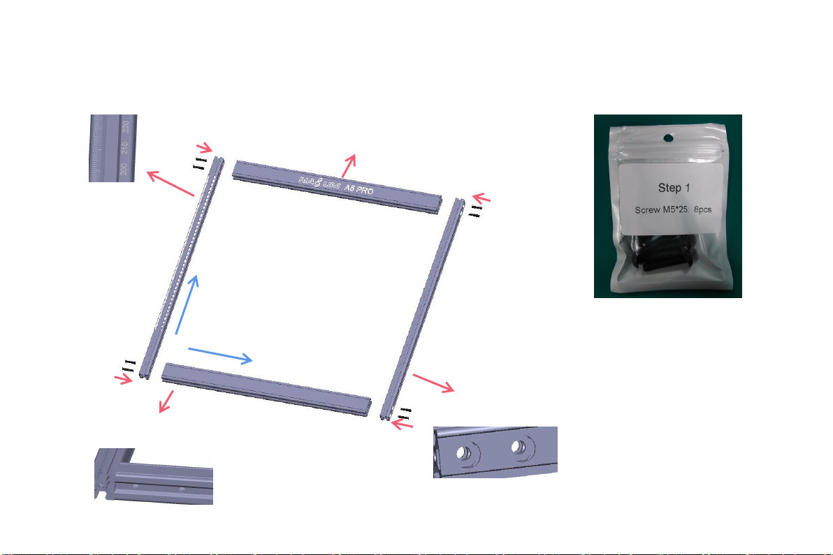
S t e p 1
Installation Manual:
1. Find the four large profiles in the picture
above, place the four profiles as shown, and
pay attention to the direction of the profiles.
2. Tighten the M5 screw in the shaft, and judge
whether you have installed it correctly through
the enlarged view details.
Nota:
a. Place the screws, but do not tighten them.
b. Then tighten the screws diagonally.
c. Tools required, M5 Allen key+M5 screws.
Logo side
up
The hole side faces
outward
Cut side outward
X
Y
Tick mark font
direction
Step1 Required components:
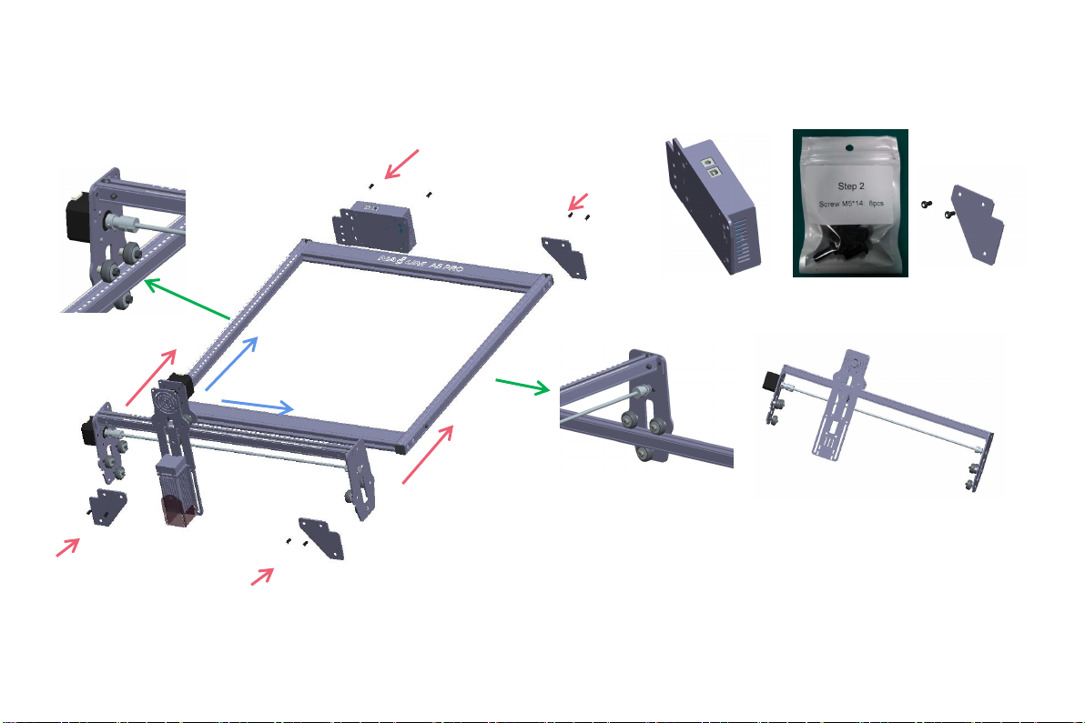
S t e p 2
Installation Manual:
1.Push the X-axis component into the base frame
in the direction shown in the figure. Adjust the
eccentric nut appropriately.
2.Install the control box as shown.
3. Use an M5 Allen key to install 3 Support gasket.
Control box *1 M5 screws*8 Support gasket *3
X-axis components*1
Step2 Required components:
1
1
2
3
3
3
The guide rail passes through
the middle of the 3 rollers.
Loosen the distance between the
upper and lower guide wheels
appropriately.
Y
X
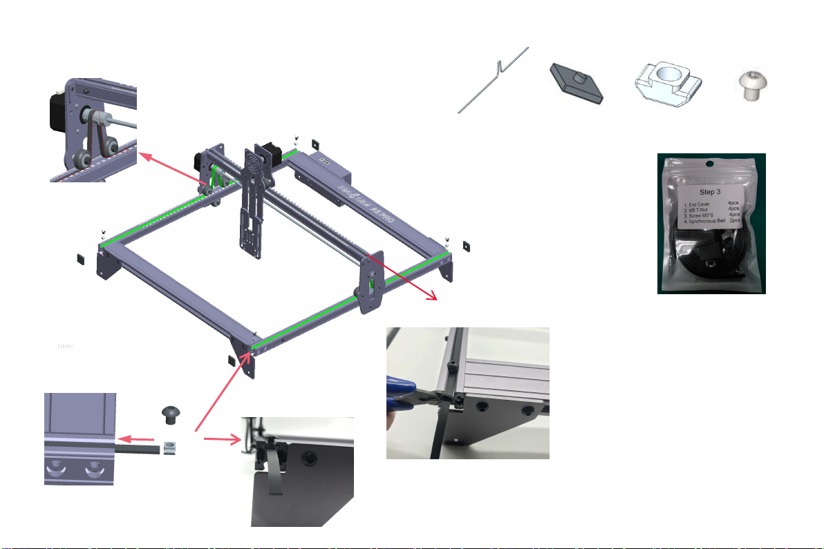
Installation Manual:
1. Install two synchronous belts as shown in the figure. First
tighten one end with a T-nut, then pass the other end
through the roller on the X-axis assembly as shown in the
figure, and finally tighten the other end and fix it with a T-
nut.
2. T-nut fixing method (Push the T-nut from the groove on
the end of the profile, and then use the screw to tighten
the T-nut), the T-nut is as close to the end of the profile as
possible, and cut off the excess belt.
3. Cover the profile end cover (the side of the end cap with
protrusions is facing down)
TIPS:
The installation of the Y-axis synchronous belt can refer to
the installed synchronous belt on the X-axis
assembly.Determine whether the timing belt is tight
enough: press the position shown in Figure 4 with your
fingers, and if there is no obvious deformation, it is tight
enough. If the deformation is large, loosen one end of the
T-nut and tighten the timing belt, and then tighten the T-
nut.
1
3
3
3
3
Type T Nut *4 Type T Nut Lock
screws*4
2
Profile end cover *4Synchronous belt *2
Step3 Required components:
4
Tighten the T nut
and cut off the
excess belt.
5
S t e p 3
Indice
Lingue:


