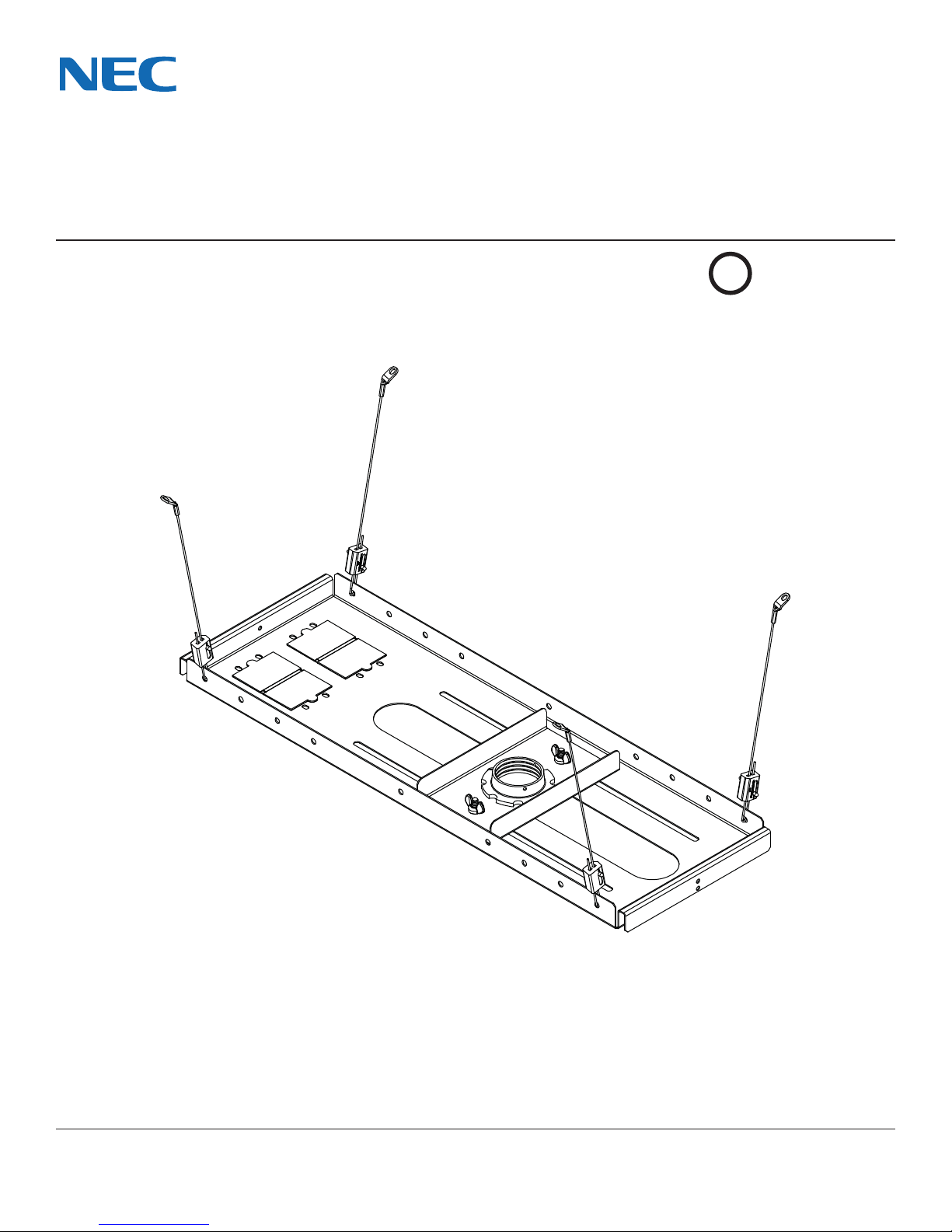
NEC NP-M260W Guida

Model: SCP200
3215 W. North Ave. • Melrose Park, IL 60160 • (800) 865-2112 or (708) 865-8870 • Fax: (708) 865-2941 • www.peerlessmounts.com
Maximum Load UL Capacity: 60 lb (27.2 kg)
Installation and Assembly:
Lightweight Adjustable Suspended Ceiling Plate for Projector
Mounts
ISSUED: 12-16-04 SHEET #: 120-9015-3 11-05-10
NEC DISPLAY SOLUTIONS OF AMERICA, INC.
©
UL
USC

ISSUED: 12-16-04 SHEET #: 120-9015-3 11-05-10
2 of 6
Visit the Peerless Web Site at www.peerlessmounts.com For Technical Support Contact Peerless Mounts at 1-800-729-0307 or 708-865-8870.
Table of Contents
Parts List.................................................................................................................................................................................3
Installation to Suspended Ceiling ..........................................................................................................................................4
Anchoring Ceiling Plate ..........................................................................................................................................................5
Warranty Information ..............................................................................................................................................................6
Tools Needed for Assembly
•stud finder ("edge to edge" stud finder is recommended)
•phillips screwdriver
•hammer
•wire cutters
•drill
•5/16" bit for concrete surface
•5/32" bit for wood studs
NOTE: Read entire instruction sheet before you start installation and assembly.
• Do not begin to install your product until you have read and understood the instructions and warnings contained
in this Installation Sheet. If you have any questions regarding any of the instructions or warnings, call Peerless
customer care at 1-800-729-0307.
• This product should only be installed by someone of good mechanical aptitude, has experience with basic building
construction, and fully understands these instructions.
• Make sure that the supporting surface will safely support the combined load of the equipment and all attached
hardware and components.
• Never exceed the Maximum UL Load Capacity.
• Always use an assistant or mechanical lifting equipment to safely lift and position equipment.
• Tighten screws firmly, but do not overtighten. Overtightening can damage the items, greatly reducing their holding
power. See suggested torque values where applicable within these instructions.
• This product is intended for indoor use only. Use of this product outdoors could lead to product failure and personal
injury.
• When installing or adjusting the ceiling mount, do not use adhesives, lubricants or oils to prevent the screws from
loosening. If you use adhesives, lubricants, or oils to prevent the screws from loosening, the casing may crack and
the projector may fall, causing serious injury and damage to the projector.
WARNING

ISSUED: 12-16-04 SHEET #: 120-9015-3 11-05-10
3 of 6
Visit the Peerless Web Site at www.peerlessmounts.com For Technical Support Contact Peerless Mounts at 1-800-729-0307 or 708-865-8870.
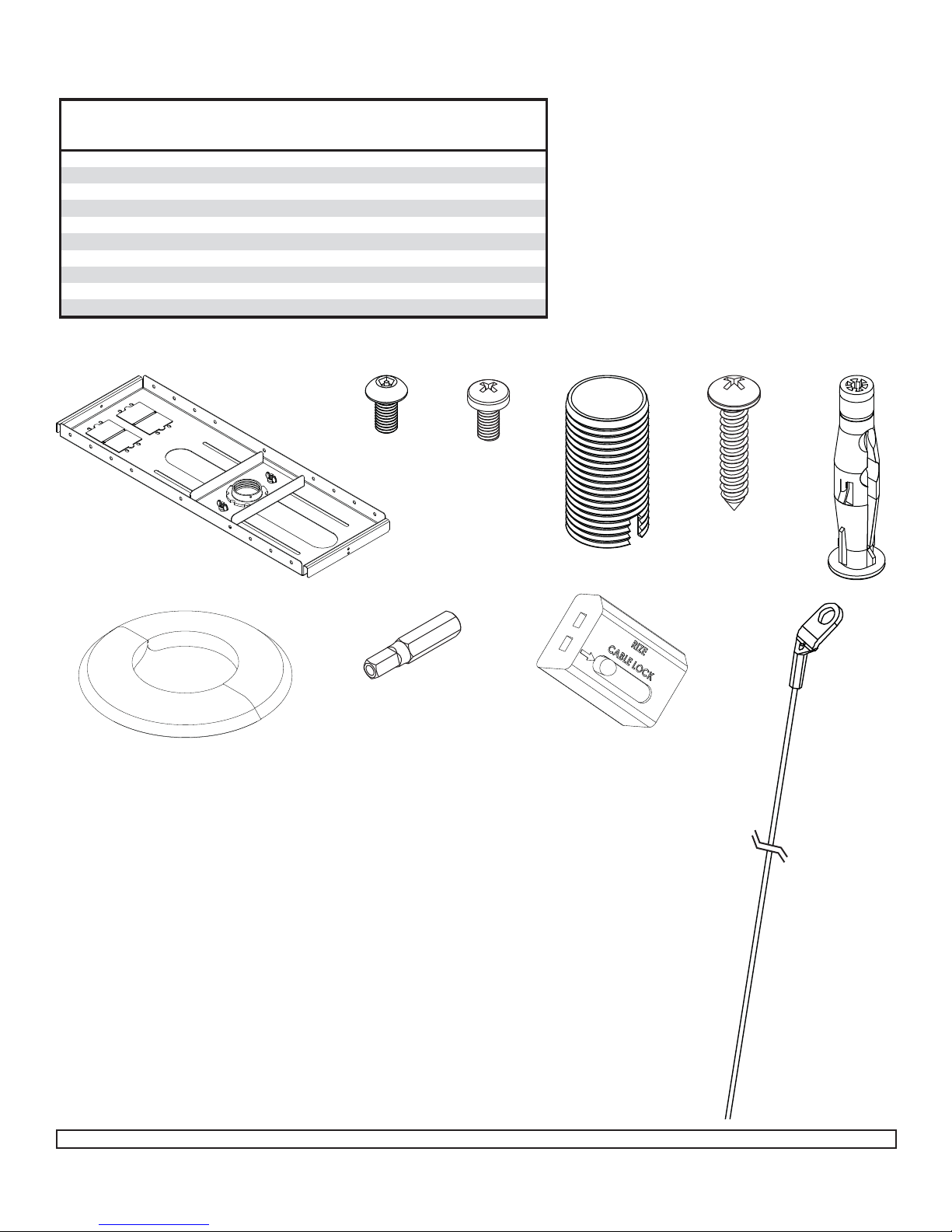
Before you start check the parts list to insure all of the parts shown are included.
NOTE: You may not need all hardware provided.
NOTE: Some parts may appear slightly different than illustrated.
A
J
FHGD
CE
I
B
Description Qty. Part #
Aceiling plate 1 055-2983
BM5 x 10 mm penta pin screw 1 505-9010
CM5 penta pin driver 1 520-9249
DM5 x 10 mm self tapping screw 2 520-9250
Esteel cable 4560-0757
Fflush mount tube 11446-014
Gwood screw 4510-9157
Hconcrete anchor 4590-0320
Icable lock 4560-0756
Jescutcheon plate 1 1418-001
A
Parts List

ISSUED: 12-16-04 SHEET #: 120-9015-3 11-05-10
4 of 6
Visit the Peerless Web Site at www.peerlessmounts.com For Technical Support Contact Peerless Mounts at 1-800-729-0307 or 708-865-8870.
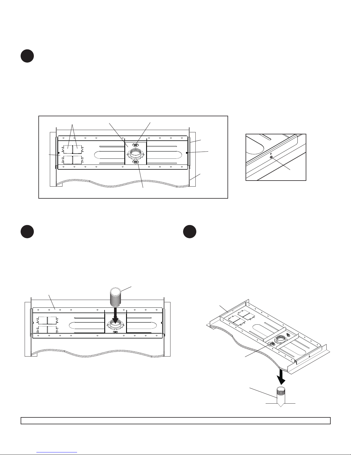
Place ceiling tray (A) in grid above 24" x 24" or 24" x 48" false ceiling tile so that lip of ceiling tray (A) rests on
ceiling runners as shown in figure 1.1. Place in desired position and install 1/4-20 self tapping screws (D) into
sides of ceiling tray (A). NOTE: If collar mount plate is positioned to the right, screw (D) can be installed into
holes of outside flange on ceiling tray (A). If ceiling runner height is low install screw (D) into lower hole as shown
in figure 1.2. Slide collar mount plate to desired position. Using hole in collar mount plate, mark false ceiling tile
where hole will be cut. Slide collar mount plate out of the way. Cut out 2.25" hole in false ceiling tile. Slide collar
mount plate back into position and tighten all carriage bolts and wing nuts.
Remove knock-outs before installing electrical box.
IMPORTANT: Ceiling Tray (A) is designed to fit above a 24" (610 mm) x 24" (610 mm) section of a conventional
suspended ceiling system. It may also be mounted above 24" x 48" conventional suspended ceiling. Ceiling
runners (see figure 1.1) should have a "T" cross section and a minimum height of 1.5" (38 mm).
AD
D
CEILING
RUNNER
OUTSIDE
FLANGE
COLLAR MOUNT PLATE
KNOCK-OUTS CARRIAGE BOLT
WING NUTS FIGURE 1.1
FIGURE 1.2
From the top down, thread flush mount tube (F)
down through retaining collar in adjustable collar
mount plate.
Snap escutcheon plate (J) around flush mount
tube or extension column and slide up until flush
with ceiling tile.
Skip to step 3.
F
For Flush Mounting Applications
From the bottom up, thread extension column
(not included) up through retaining collar in
adjustable collar mount plate. Align notch in
extension column with hole in collar and fasten
with M5 x 10 mm penta pin screw (B) using penta
pin driver (C).
Snap escutcheon plate (J) around flush mount
tube or extension column and slide up until flush
with ceiling tile.
For Extension Column Applications
A
A
B
2
1
3
1 1/2" EXTENSION
COLUMN (SOLD
SEPARATELY)
(UL LISTED EXT OR AEC
SERIES)

ISSUED: 12-16-04 SHEET #: 120-9015-3 11-05-10
5 of 6
Visit the Peerless Web Site at www.peerlessmounts.com For Technical Support Contact Peerless Mounts at 1-800-729-0307 or 708-865-8870.
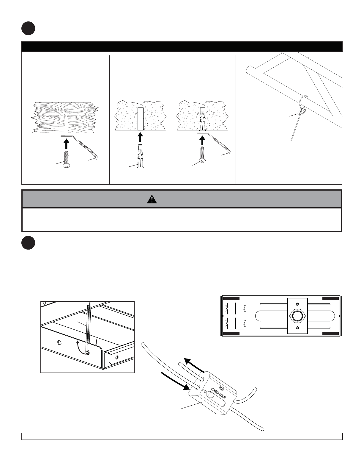
Drill holes for four ceiling anchors (detail 2). Position the holes so that when the steel cables (E) are attached and
taut they will angle out at 15°.
Insert loose end of steel wire (E) through one end of cable lock (I) as shown below. NOTE: Steel wires can only
insert one way through cable lock as shown in figure 5.2.
Route steel wires through hole of ceiling tray as shown in figure 5.1. Loop steel cables through ceiling tray (A)
where indicated by black rectangles in detail 3. Finish by routing loose end of steel cable through other end of
cable lock. Feed cable through cable lock until all cables are taut.
When this step is complete, the weight of the ceiling tray should be supported by the steel cables.
© 2007 Peerless Industries, Inc. All rights reserved.
Peerless is a registered trademark of Peerless Industries, Inc.
All other brand and product names are trademarks or registered trademarks of their respective owners.
4
5
E
FIGURE 5.1
FIGURE 5.2
DETAIL 3 - TOP VIEW
I
Wood Joists or Beams
Drill 5/32" (4 mm) dia.
holes to a minimum depth
of 1.5" (38 mm). Secure
steel cables (E) using
wood screw (G)
Solid Concrete
Drill 5/16" (8 mm) dia. holes to a mini-
mum depth of 2.25" (57 mm). Hammer
in concrete anchors (H) and secure
steel cables (E) with wood screw (G)
Truss Ceiling
No anchor required. Loop
upper end of steel cable (E)
around ceiling truss and down
into hole of cable loop. Pull
steel wire tight.
GEE
E
HG
DETAIL 2
BLACK RECTANGLES REPRESENT CORRECT
POSITIONS FOR STEEL WIRE
• It is the responsibility of the installer to verify that the ceiling to which the suspended ceiling kit is anchored will safely
support the combined load of all attached components (Projector Mount, Extension Column, etc.) and equipment.
WARNING

ISSUED: 12-16-04 SHEET #: 120-9015-3 11-05-10
6 of 6
Visit the Peerless Web Site at www.peerlessmounts.com For Technical Support Contact Peerless Mounts at 1-800-729-0307 or 708-865-8870.
© 2008 Peerless Industries, Inc.
Peerless Industries, Inc. establishes a warranty period of five years for products manufactured or supplied by Peerless. This period commences from the date of
sale of the product to the original consumer, but will in no case last for more than six years after the date of the product’s manufacture. During the warranty period
such products will be free from defects in material and workmanship, provided they are installed and used in compliance with the instructions established by
Peerless Industries, Inc. Subject to applicable legal requirements, during the warranty period Peerless will repair or replace, or refund the purchase price of, any
such product which fails to conform with this warranty.
Any other warranties prescribed by the law which may apply with respect to such products also are limited in duration to the warranty period specified in this
Limited Five-Year Warranty.
This warranty does not cover damage caused by (a) service or repairs by the customer or a person who is not authorized for such service or repairs by Peerless
Industries, Inc., (b) the failure to utilize proper packing when returning the product, (c) incorrect installation or the failure to follow Peerless’ instructions or warnings
when installing, using or storing the product, or (d) misuse or accident, in transit or otherwise, including in cases of third party actions and force majeure.
In no event shall Peerless be liable for incidental or consequential damages or damages arising from the theft of any product, whether or not secured by a security
device which may be included with the product.
This Limited Five-Year Warranty is in lieu of all other warranties, expressed or implied, and is the sole remedy with respect to product defects. No retailer, dealer,
distributor, installer or other person is authorized to modify or extend this warranty or impose any obligation on Peerless in connection with the sale of any product
manufactured or supplied by Peerless.
This warranty gives specific legal rights, and you may also have other rights provided by the national legislation of the country in which you purchased such
product.
LIMITED FIVE-YEAR WARRANTY
www.peerlessmounts.com
Altri manuali per NP-M260W
1
Questo manuale è adatto per i seguenti modelli
58
Indice
Altri manuali NEC Rack e supporto

NEC
NEC NP-PH1000U Manuale utente

NEC
NEC Wall Mount PDW S 32-55 P (WMS 32-55 P Manuale utente

NEC
NEC N8154-46 Manuale utente

NEC
NEC NP02LK Manuale utente

NEC
NEC NP05WK1 Guida

NEC
NEC LT30 - XGA DLP Projector Guida

NEC
NEC PDWHM-M Manuale utente

NEC
NEC IW77 Manuale utente

NEC
NEC WM-46UN Wall Mount Portrait and Landscape Manuale utente

NEC
NEC NP-UM330W Series Guida