Nedap VP1007-B Manuale utente

Instruction Manual
VP1007-B
Installation manual
Version 01.000 / November 2020 / EN
Original instructions
Livestock Management

Copyright
Copyright © Nedap N.V. All rights reserved. The information in this document is subject to change without
notice, it is not to be reproduced in any way, in whole or in part, without the written consent of Nedap N.V. All
trademarks referenced belong to their respective owners.
Disclaimer
Nedap N.V. has made every effort to ensure the accuracy of the information contained in this document.
However, Nedap N.V. makes no representations or warranties whatsoever whether express or implied as
to the accuracy, correctness, completeness or fit-for-purpose or suitability for the purpose of this product.
You use the products at your own risk. Nedap N.V. excludes any liability to the maximum extent permitted by
applicable law for the damages caused by errors or failures made during the installation or improper use of
this product or by not applying the instructions stated in this document. Nedap N.V. reserves the right to make
improvements or amendments to this document and/or the products described therein at any time without any
notification. The latest version of this document can be found on the Nedap Livestock Management business
portal (www.nedap.com/livestockmanagement-portal). Please download the latest version of this document (by
yourself or reseller) and keep a copy for your own records. This document can be published in various languages
but only the English language version will prevail. Nedap N.V. assumes no responsibility for any errors caused for
the translations into another language.
Warranty and spare parts
Please consult the Nedap products dealer from whom you purchased this product, in regards to the applicable
warranty conditions. This product cannot be used for any other purpose as described in this document. If
the product is not installed according to this document; the warranty provided is not applicable. At the sole
discretion of Nedap N.V., Nedap N.V. may decide to change the conditions of the warranty policy. You agree
that Nedap N.V. is able to compensate you the pro-rata value of the warranty involved rather than replacing
or repairing the product depending on the technical or economical value of the product. Prior to applying the
warranty, please verify if you comply with the warranty conditions of the warranty policy, whether you can
successfully apply for the replacement or repair of a defective part. Parts can only be replaced with original
Nedap parts, otherwise the warranty policy will not be applicable on the product. If the warranty is applicable,
please contact the dealer or send the defective parts to the dealer.
Additional information
For any information or questions regarding the product, please contact your own dealer.

VP1007-B / Installation manual
Version 01.000 / November 2020 / EN
1
Livestock Management
VP1007-B

VP1007-B / Installation manual
Version 01.000 / November 2020 / EN
2
Livestock Management
Content
1 Safety .................................................................................................. 3
2 VP1007-B introduction ......................................................................... 5
2.1 Extended functionality ................................................................................................... 5
3 Installation ........................................................................................... 6
3.1 Requirements for installation ........................................................................................ 6
3.1.1 Electrical requirements .................................................................................................... 6
3.1.2 Electromagnetic requirements ........................................................................................ 6
3.1.3 Tools requirements .......................................................................................................... 7
3.2 Mount the VP1007-B ..................................................................................................... 7
3.3 Wiring .............................................................................................................................. 7
3.3.1 Wiring diagram VP1007-B ............................................................................................... 9
4 Configuration ...................................................................................... 11
4.1 Configure the VP1007-B .............................................................................................. 11
4.2 Check for firmware updates ........................................................................................ 12
5 Commissioning ................................................................................... 13
5.1 Testing inputs and outputs .......................................................................................... 13
5.2 Antenna tuning ............................................................................................................. 14
5.3 Antenna adjustment ..................................................................................................... 14
5.4 Identification tests ....................................................................................................... 16
6 Troubleshooting .................................................................................. 18
7 Glossary ............................................................................................. 20
8 Technical specifications ...................................................................... 21
9 Handling instructions .......................................................................... 22
10 Compliance ........................................................................................ 23
11 Appendix ............................................................................................ 25
11.1 VP1007-B reader LED indicators ................................................................................ 25
11.2 VP1007-B reader menu overview ............................................................................... 26
11.3 Wiring color coding ...................................................................................................... 28

VP1007-B / Installation manual
Version 01.000 / November 2020 / EN
3
Livestock Management
1 Safety
Read this manual before using this product. Failure to follow the instructions and safety precautions in this
manual may result in serious injury or death. Keep this manual in a safe location for future reference.
Symbols used in the manual
Danger
Indicates a hazardous situation that, if not avoided, will result in death or serious
injury.
Warning
Indicates a hazardous situation that, if not avoided, could result in death or serious
injury.
Caution
Indicates a hazardous situation that, if not avoided, could result in minor or moderate
injury.
Indicates important information but not hazard related.
Suggestions and advice to perform certain tasks more easily.
General safety instructions
Warning
Always turn off the mains power supply when working on the electrical installation.
Warning
Always wear proper protection when installing and maintaining the VP1007-B.
Caution
Use the VP1007-B only with a suitable power supply. The power supply or power adapter must comply with
local regulations for a SELV, limited power (NEC class2, ps2) output (e.g. Nedap VP2001-B or Nedap power
adapter (P/N 9223126)).
Caution
Installation and service should only be done by locally qualified personnel.
Caution
Install the system according to the local rules and regulations.
Working environment
Caution
The installation area must be free from any obstacles, including animals.

VP1007-B / Installation manual
Version 01.000 / November 2020 / EN
4
Livestock Management
Caution
Make sure all components are installed out of reach of animals.
Caution
Make sure all cables are properly concealed, and form no danger for stumbling.
Caution
Take into account the high concentrations of ammonia when installing and maintaining the VP1007-B in pig
barns.
Animal welfare and safety
The automated actions of the Nedap Livestock Management systems do never discharge the installer and the
user of the system from his/her responsibility to assure and to take care of the well-being of the animals.

VP1007-B / Installation manual
Version 01.000 / November 2020 / EN
5
Livestock Management
2 VP1007-B introduction
The Nedap VP1007-B Transceiver is a reader and input/output controller that is used for feeding, weighing,
milking, heat detection, sorting/routing, identification and so on.
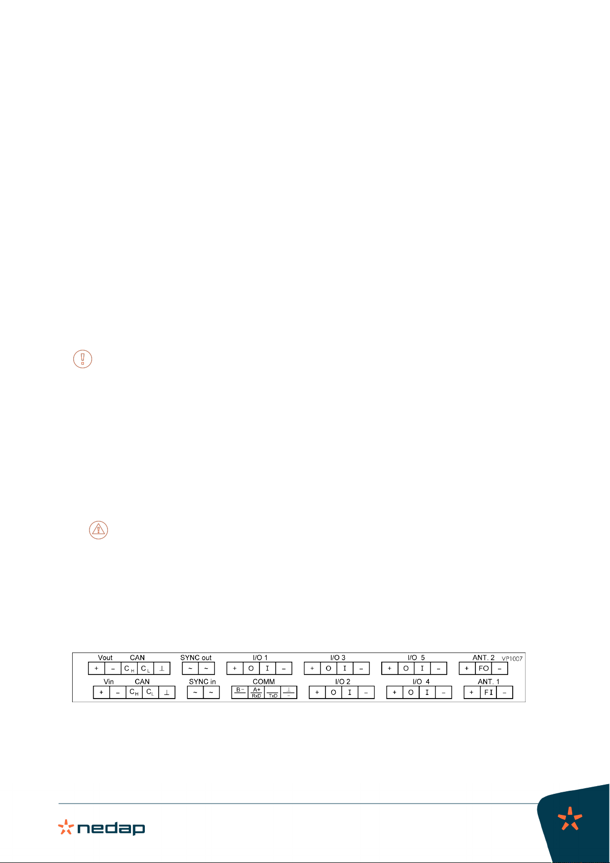
Connectors:
• 2 Antenna connections, 1 active at the time
• FDX sync / HDX sync
HDX and other extra ID options are only available by license. If no license is purchased for the VP1007-
B, these options can be tested for a 24-hour period.
• 1 CAN channel with 2 connectors
• 5 Outputs (max 2A)
• 5 Inputs
• 1 RS485 / RS232 communication channel
Features:
• Identification of tags
• Activates and controls e.g. lights, motors, valves, relays
• Reads the input for e.g. sensors, switches
• Special serial interface (RS485 / RS232) for connecting sensors with serial interface
All currently available Nedap Livestock antennas can be used.
2.1 Extended functionality
The new generation V-packs (V-pack B types) are based on a new transmitter-receiver module with an improved
way of animal identification based on Digital Signal Processing (DSP) technology.
The V-pack B types offer the following new features:
• Notch Filter (nF): This option suppresses the signals that are received from long wave transmitters near
Berlin, Frankfurt and Budapest. Especially large antennas such as the Walk Through and Walk Past antennas
are sensitive for this. Noise reduction antennas will not need this notch filter as they already suppress these
long wave transmitter signals.
These new options and the HDX mode must be activated with a license on the VPU (VP8001/VP8002). If the V-
pack is not connected to a VPU, a license for the V-pack must be purchased.
Nedap: If no license is purchased for the VPU or the V-pack, the HDX and/or Notch Filter options can be
tested for a 24-hour period. For more information see the menu overview of the V-pack in the Appendix.
To check if the VP1007 is a B version, a "b" will appear on the display shortly after the VP1007-B is booted.
If a system uses HDX tags, and a VP1007 has to be replaced with a VP1007-B, there are two options:
1. Order a special VP1007-B with HDX license pre-installed on the VP1007-B, or:
2. Order a normal VP1007-B FDX only and add a separate HDX license to the VPU for this VP1007-B.

VP1007-B / Installation manual
Version 01.000 / November 2020 / EN
6
Livestock Management
3 Installation
Do not operate the product without first reading this chapter and the safety section at the beginning of this
manual.
Warning
Failure to follow safety precautions in this chapter could result in serious injury or death.
3.1 Requirements for installation
3.1.1 Electrical requirements
Mains power
Make sure the mains power supply for the system is easily accessible and not too far away from the barn
in which the units are placed. The power sockets shall be installed near the equipment and must be easily
accessible.
Caution
Nedap power supplies must be connected to a power socket with protective earth (PE). Always use a 3-pole
connector with a PE contact.
If there is no PE available, create a PE next to the power socket to be used for each power supply. The
properties of a correct PE depend on local circumstances and legislation. Always comply with local rules and
regulations when installing earth electrodes.
Cabling
Install the Velos CAN cable(s) inside a plastic (PVC) conduit.
Do NOT install cables directly to metal ceiling, trusses, feed lines and power lines.
Lightning protection
It is important to follow closely the guidelines that are described in this section, in order to minimize risk of
damage on Velos systems in case of lightning. Nedap does, however, not accept any responsibility for damage
caused by high voltage (such as lightning), as described in the Warranty Policy.
Protective Earth (PE)
PE is meant for safety related issues such as electric shocks to humans or animals. PE will not protect devices
(sufficiently) when they are struck by lightning. Normally PE is situated next to the main power source only.
Grounding
Grounding is a connection to the ground, but not Protective Earth, for example a metal roof that is connected to
different earth electrodes in order to lead high peak currents (such as lightning) to the earth.
Nedap can never be kept responsible for incorrect functioning of networks or any damage arising from the
recommendations mentioned in this document.
3.1.2 Electromagnetic requirements
Nedap Animal Identification uses radio waves in compliance with ISO 11784/11785 standard and local
regulations.

VP1007-B / Installation manual
Version 01.000 / November 2020 / EN
7
Livestock Management
Notwithstanding all due precaution by Nedap, Nedap Animal Identification may not function optimally due
to devices that emit radio waves, such as (but not limited to) variable frequency drives, electronic ballasts of
lighting systems, power supplies, electronic converters of solar panels/windmills and (long) wave radio stations,
which may cause interference with Nedap Animal Identification.
No claims, representations or warranties, whether expressed or implied, are made by Nedap as to the
performance, reliability, durability and safety of Nedap Animal Identification used in conjunction with
abovementioned or other devices.
In order to achieve optimal performance of Nedap Animal Identification, the electrical installation on the farm
needs to meet the conditions that are shown below.
• Maximum allowed environmental noise level: 10 dBµA/m quasi peak, according to CISPR 16-1-1.
• Maximum allowed conducted noise: according to EN55032: 2015.
3.1.3 Tools requirements
• Screwdriver size 0.4 x 2.5 mm (0.016 x 0.098 in.) for the LAN connector of the V-pack.
3.2 Mount the VP1007-B
Mount the VP1007-B in a dust and splash proof housing, preferably a Nedap V-box:
If the VP1007-B is installed as a part of a complete Nedap system, use the installation manual of this
system. The installation manual can be obtained from your dealer or on our Business portal: http://
www.nedap.com/livestockmanagement-portal.
1. Mount the V-box according to the installation instructions of the V-box, which can be obtained from your
dealer or on our Business portal: http://www.nedap.com/livestockmanagement-portal.
2. Mount the VP1007-B in the V-box:
a. Pull down the 2 lips on the back side of the VP1007-B.
b. Place the VP1007-B on the top of the DIN rail inside the V-box.
c. Hinge down the VP1007-B until it clicks in.
d. Push up the 2 lips to secure the VP1007-B to the DIN rail.
3. Close the V-box.
Caution
Make sure to always close the V-box with the V-box cover and check the correct position of the cover
seal.
3.3 Wiring
Connectors

VP1007-B / Installation manual
Version 01.000 / November 2020 / EN
8
Livestock Management
Connector Symbol Description
Vout +Output voltage 25 VDC, ± 20%
–Minus
+Input voltage 25 VDC, ± 20%Vin
–Minus
CHCAN high (cable twisted pair with CL )
CLCAN low (cable twisted pair with CH )
CAN
CAN bus cable shielding
~Antenna synchronization, AC (no plus or minus, cable must be twisted pair)SYNC in
~Antenna synchronization, AC (no plus or minus, cable must be twisted pair)
~Antenna synchronization, AC (no plus or minus, cable must be twisted pair)SYNC out
~Antenna synchronization, AC (no plus or minus, cable must be twisted pair)
I/O 1/2/3/4/5 +Output max. 2 A (total of all outputs 4 A)
OOutput max. 2 A (total of all outputs 4 A)
IInput
–Minus for output (O) and minus input (I)
COMM B- Receive data (RS-485)
A+ / RxD A+ = Send data (RS-485) / RxD = Receive data (RS-232)
TxD Send data (RS-232)
/ – Shield (RS-485) / minus (RS-232)
ANT. 1 +Plus (core of coax cable or plus of antenna cable)
FI Frequency synchronization (of the antenna signal) in (must be connected to the
FSYNC-O connector of the other V-pack)
–Minus (shield of coax cable or minus of antenna cable)
ANT. 2 +Plus (core of coax cable or antenna cable)
FO Frequency synchronization (of the antenna signal) out (must be connected to
the FSYNC-I connector of the other V-pack)
–Minus (shield of coax cable or antenna cable)
Velos CAN cable
Velos CAN cable Wiring Wire color
1. Power +25 Vdc
2. Power –
3. CAN High
4. CAN Low
5. HF synchronization
6. HF synchronization
7. Shield communication wires
8. Shield synchronization wires
1. Red
2. Black
3. Blue
4. Blue/white
5. Orange
6. Orange/white
7. Blank
8. Blank
Indice
Altri manuali Nedap Sistema RFID

Nedap
Nedap uPASS TARGET Manuale utente

Nedap
Nedap TRANSIT Entry Manuale utente

Nedap
Nedap Transit Ultimate Manuale utente

Nedap
Nedap NVITE Manuale utente

Nedap
Nedap ANPR LUMO Manuale utente

Nedap
Nedap uPASS Access Manuale utente

Nedap
Nedap PROX-BOOSTER 2G Manuale utente

Nedap
Nedap LibAssist Manuale utente

Nedap
Nedap uPASS REACH Manuale utente

Nedap
Nedap TRANSIT Manuale utente


