Nel-Tech Labs iLink Manuale di istruzioni

iLink LCD
by
Nel-Tech Labs, Inc.
Installation & User Manual


Index:
Introduction ........................................................................................................................
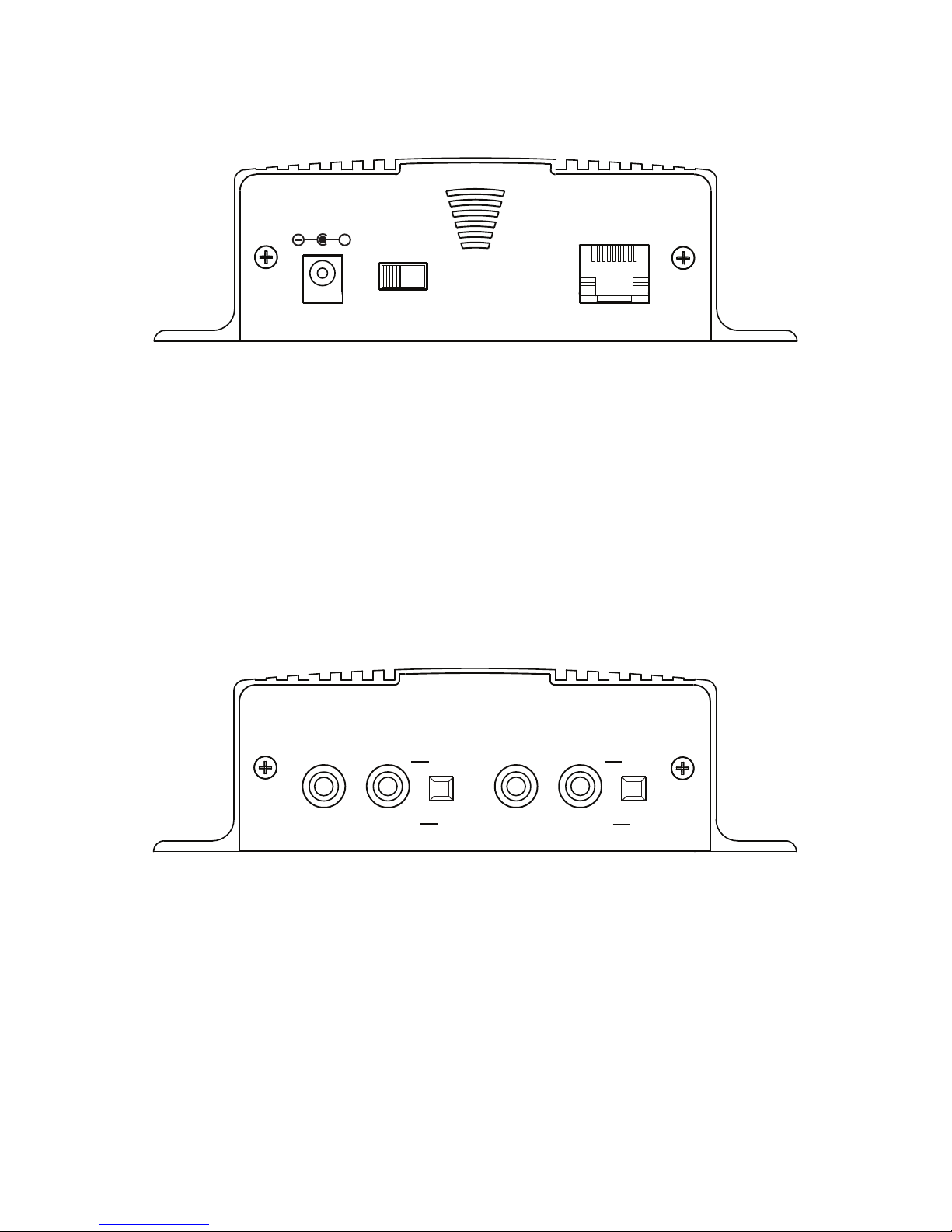
iLink Layout Summary.....................................................................................................
LCD Layout Summary ......................................................................................................
Web Browser .....................................................................................................................
Installation .......................................................................................................................
Connectivity Test/Volume Adjustments................................................................................
Troubleshooting ................................................................................................................
Warranty & FCC ....................................................................................................................
3
3
4 - 5
6
7
8
9 - 11
12
13
Introduction:
The iLink LCD is an Internet downloadable messaging system utilizing state-of-the-art MPEG compression to achieve
truly stunning near-CD quality audio storage and playback. All unit management and audio downloads are accomplished by
your dealer using a special controller software suite. When an update is needed your dealer connects to the iLink via your
high-speed Internet connection and digitally transfers the MP3 audio les and conguration settings you need. Changes can
be initiated on demand, scheduled from minutes to weeks, or the iLink can be instructed to connect automatically and load
new audio.
Unpacking and Inspection:
Before you begin installation, unpack and verify you have all the correct parts.
(1) iLink LCD
(1) 12VDC @ 500mA power supply
(1) Ethernet cable
(1) RCA to RCA cable
(1) RCA to 3.5mm adapter
(2) Wall mount screws
(1) Instruction manual
If you are missing any of these parts STOP and call your dealer.

iLink Layout Summary:
Front of Unit
12VDC - This is where the supplied 12VDC @ 500mA power pack is connected.
POWER - Use this switch to turn the unit ON and OFF.
LAN - This jack connects to the local Ethernet that allows the iLink connectivity to the Internet. The jack also has
two built in LEDs that report back network activity and speed status.
Rear of Unit
CHANNEL A or B (IN) - This signal level jack allows an external BGM (Background Music) source to be fed
through the iLink unit.
CHANNEL A or B (OUT) - This jack connects to a phone systems MOH input or a PA amplier.
8Ω or 600Ω - This switch changes the output impedance of the CHANNEL A or B (OUT) jack.
4
CHANNEL A CHANNEL B
IN OUT IN OUT
600Ω
▄
█
MADE IN USA
8Ω ▄8Ω
600Ω
█
12VDC
500mA
+
POWER
ON
(1)
OFF
(0)
LAN

Top of Unit
MENU BUTTON - Keypad button used to cycle through menu items.
SELECT BUTTON - Keypad button used to select menu item to be changed.
UP and DOWN BUTTONS - Keypad buttons used to make changes to selected items.
2 x 16 LCD - White lettering on blue backlighting LCD used to display unit information.
iLink v07.00.a
10.1.1.206
5

LCD Menu
iLink v07.00.a
10.1.1.206
Output A
Volume = XX
Output B
Volume = XX
Input A BGM
Volume = XX
Input B BGM
Volume = XX
Monitor Speaker
Source = XX
IP Mode
DHCP or Static
IP
XXX.XXX.XXX.XXX
Subnet
XXX.XXX.XXX.XXX
Gateway
XXX.XXX.XXX.XXX
Connect-Back IP1
XXX.XXX.XXX.XXX
Connect-Back IP2
XXX.XXX.XXX.XXX
Connect-Back Prt
XXXX
PRESS UP ARROW
TO CONNECT-BACK
Format
& Reboot
Firmware Version
vXX.XX.X
MAC ADDRESSS
000000000000
qp Changes Volume
qp Changes Volume
qp Changes Volume
qp Changes Volume
qp Cycles Internal Speaker to OFF, A or B
= Menu Button Push
= Select Button Push
qp Changes Mode
“Select” ashes rst octet
qp Changes digit
“Select” conrms and moves to next octet
“Up to Conrm”
“Down to Cancel”
“Up to Conrm”
“Down to Cancel”
“Select” ashes rst octet
qp Changes digit
“Select” conrms and moves to next octet
“Up to Conrm”
“Down to Cancel”
“Select” ashes rst octet
qp Changes digit
“Select” conrms and moves to next octet
“Up to Conrm”
“Down to Cancel”
Note:
Changes to IP Settings only available in STATIC
MODE
If MAIN MENU is idle for more than 30 seconds the
LCD reverts back to MAIN SCREEN
If SUB MENU is idle for more than 300 seconds the
LCD reverts back to MAIN SCREEN and CANCELS
any current changes.
}Locked if local volume
control is disabled
“Up to Conrm”
“Select” ashes rst octet
qp Changes digit
“Select” conrms and moves to next octet
“Up to Conrm”
“Down to Cancel”
“Select” ashes rst octet
qp Changes digit
“Select” conrms and moves to next octet
“Up to Conrm”
“Down to Cancel”
qp Changes Port “Up to Conrm”
“Down to Cancel”
“Up to Conrm”
“Down to Cancel”
6

Web Browser (Feature on rmware version 07.09X or higher)
The iLink LCD has a built-in password protected web browser that will display the units serial number, rmware
version and MAC address. This browser will also allow the units communication mode, connect-back address
and port to be changed.
When changing Mode either DHCP or STATIC must be typed in the “New Settings” column. When
changing to STATIC mode the IP, Subnet and Gateway must all be entered or the settings will not take
when submitted. The Status will indicate if the settings have been updated to the unit.
7

Installation :
Step 1: Wall or shelf mount the unit. Rubber feet and screws are supplied in the accessory kit.
Step 2: Verify the power switch on the right side of the unit is set to OFF. Attach the included power pack to a
wall or power strip receptacle, then attach the other end to the jack on the right side of the unit labeled 12VDC.
Step 3: If connecting unit to an amplier make sure it is turned OFF for this part of the installation.
Step 4: Connect a RCA cable (supplied in the accessory kit) to the CHANNEL A (OUT) jack on the left side of
the unit. Connect the other end of the RCA cable to a phones MOH port, PA amplier or speaker. For dual output
applications follow the same procedure for the CHANNEL B (OUT).
Step 5: (Optional) For messaging only applications the existing BGM (Background Music) can be fed through
the iLink. Connect the audio source to the CHANNEL A or B (IN) jack(s) on the left side of the unit. This jack
must only be fed signal level audio - ANY AMPLIFIED AUDIO WILL DAMAGE THE UNIT.
Step 6: Connect an Ethernet cable (supplied in the accessory kit) to the LAN jack on the right side of the unit.
Connect the other end to a 10/100 speed switch or hub.
Wiring Diagram
Left Side Right Side
To Switch or Hub
To MOH or PA
From BGM Source
(Optional)
To MOH or PA
(Optional)
CHANNEL A CHANNEL B
IN OUT IN OUT
600Ω
▄
█
MADE IN USA
8Ω ▄8Ω
600Ω
█
12VDC
500mA
+
POWER
ON
(1)
OFF
(0)
LAN
From BGM Source
(Optional)
8

9
Connectivity Test:
Step 1: Verify the power switch on the right side of the unit is set to ON.
Step 2: On the LCD menu verify unit has a valid IP, subnet and gateway.
IP
010.001.001.206
Subnet
255.255.255.128
Gateway
010.001.001.120
Step 3: On the LCD menu go to the “PRESS UP ARROW TO CONNECT-BACK” and press the UP ARROW.
PRESS UP ARROW
TO CONNECT-BACK
Step 4: The LCD will display the “FORCING CONNECT PLEASE WAIT”
FORCING CONNECT
PLEASE WAIT
Step 5: If there is a Connect-Back record waiting for the unit then the LCD will display “ACTIVE CONNECT
XXX.XXX.XXX.XXX”.
ACTIVE CONNECT
10.1.1.171
If there is no record waiting then it will display “CONNECT TO XXX.XXX.XXX.XXX” for one second on the
LCD to conrm a successful connectivity.
CONNECT TO
10.1.1.171
Example:
Example:
Example:

and/or
10
CHANNEL A CHANNEL B
IN OUT IN OUT
600Ω
▄
█
MADE IN USA
8Ω ▄8Ω
600Ω
█
Channel A & B Output Level Adjustments:
Step 1: Verify CHANNEL A or B (OUT) is connected to either a phone’s MOH port, PA amplier or speaker.
Step 2: Verify the unit is playing audio by listening to the internal monitor speaker.
Monitor Speaker
Source = XX
qp Cycles Internal Speaker to OFF, A or B
CHANNEL A CHANNEL B
IN OUT IN OUT
600Ω
▄
█
MADE IN USA
8Ω ▄8Ω
600Ω
█
Step 4: Adjustment of the stored audio output level can be done through the LCD and Menu. Depending upon
the application either call into the phone system and be placed on hold OR listen to the PA systems speakers to
ne tune volume.
Output A
Volume = XX
Output B
Volume = XX
qp Changes Volume
If you see a “LOCKED VOLUME SETTINGS” message then the dealer has locked this setting.
Note: This setting only adjusts the units audio outputs and does not adjust the volume of the internal speaker!
Step 3: Depending upon the device the 8Ω/600Ω switch may need to be pushed to better match the impedance of
the device the iLink is driving.
Step 5: All audio adjustments are applied live so changes are saved to the unit instantly.
Altri manuali per iLink
1
Indice
Altri manuali Nel-Tech Labs Ricevitore


