Nexxt Solutions NHE-S100 Manuale utente

WARRANTY
nexxtsolutions.com/warranty
YEAR
2
Smart Wi-Fi light switch
Single pole

English
User guide
Thank you for purchasing the Smart Wi-Fi light switch
from Nexxt Solutions. We are excited for being a part of
making your life easier, safer and bringing peace of mind
inside and outside your home.
Package content
- Light switch (1)
- Wall plate (1)
- Plate screw (2)
- Wire nut (4)
- Quick start guide (1)
Safety information
Precautions
Please read and understand this entire manual before
attempting to assemble, install and operate this smart
electrical xture.
This product requires replacing the existing switch through
a hard-wiring process.
This smart electrical xture requires 110-220-volt AC.
This device has been tested by the manufacturer according
to all international electrical standards. However, every
state has dierent standards and rules for installing
electrical cabling and equipment in a home.
Please check with your local and state laws prior to using
this device.
Improper installation of product may cause electrical injury
to an individual.
Installation of this product must be performed by a
qualied electrician or a certied electrical technician. Do
not attempt to perform installation if you are not familiar
with hardwired electrical connections.
Improper installation can lead to loss of warranty.
Nexxt Solutions assumes no liability for the improper
installation of this product.

Product overview
1. Smart switch indicator light:
displays the status of the
wireless connection and
switch.
2. Switch: use it to manually
toggle the device on and o
3. Face plate
Red
Red
Green
Red
Red
Blinks fast
Blinks slowly
(once every
3 seconds)
Solid
Solid
O
Ready for pairing
(default mode only)
Ready for connection (AP
mode only)
Indicates that pairing is successful
and that the light switch status is ON
Indicates that the light switch is OFF
No internet connection available
LED light Status Description
Turn power o at the circuit breaker or fuse.
Use only when it’s installed with a residual current device (RCD) or
current leakage protector at home.
WARNING: For safety, this light switch must be
properly grounded.
WARNING: To avoid risk of electric shock or
electrocution, install the light switch away from
any water source.
WARNING: This light switch supports single pole
circuit only. It is not compatible with 3-way
(multi-location control) connection circuit.
WARNING: A neutral wire is needed to power the
light switch.
WARNING: This device is single band and will
only work with 2.4GHz Wi-Fi routers.
1
2
3

4. Load wire
5. Live wire
6. Neutral wire
7. Ground wire
GROUND
LOAD
LINE
NEUTRAL
4
5 6 7
Initial inspection
Before installing the electrical xture, ensure that all parts
are included in the package. If any part is missing or
damaged, do not attempt to assemble, install, or operate
this product.
Estimated installation time: about 30 minutes.
Tools that may be required but are not included for
installation
1. Phillips screwdriver
2. Flathead screwdriver
3. Pliers
4. Wire strippers/cutters
5. Circuit tester
6. Work gloves
7. Electrical tape
8. Safety goggles
1 2
3 4
5 6
7 8

Hardware installation
IMPORTANT
For safety, properly ground the switch
Always follow the code standards when installing wired
connections.
Step 1
Shut power off at the breaker
Find the breaker that controls the circuit for the junction
box where the smart light switch will be installed. Turn it to
the OFF position.
Place tape over the circuit breaker switch and verify that
power is o.
Note: you can use the circuit tester at this point to verity
that power is cut o.
ON OFF
ON OFF
ON OFF
Step 2
Remove the original switch from the wall box
Identify the Line, Load, Neutral and Ground wires.
Note: If the existing switch has two jacks, you may nd 5
wires or more. Identify the neutral, line, load and ground
wires. This smart switch only needs to use these 4 wires,
since it does not require the connection of additional
circuits.
Ground
Line
Load
Switch
(Line/Load)
Neutral

Note: a single bare copper wire is also used to
represent the ground wire in existing electrical installations.
Europe/Australia color code standard:
Blue is for neutral, brown represents the live and load
wires, and the yellow/green cable is for grounding.
Note: a single bare copper wire is also used to
represent the ground wire in existing electrical installations.
Step 3
Label your wires
Mark the corresponding cables before removing the
existing light switch.
Always follow code standards when installing wired
connections.
Note: All the images are for reference only and therefore
they must not be used as a standard.
North American color code standard:
White is for neutral, black represents the live and load
wires, and the yellow/green cable is for grounding.
GROUND
LINE LOAD
Line
Load
NEUTRAL
GROUND
LINE LOAD
Line
Load
NEUTRAL

Gently push all the excess wiring into the junction box.
Note: make sure all the wires are positioned in an
organized manner and away from the edges of the light
switch and the junction box, to avoid pinching any of the
cables, prior to completing the process.
Proceed to align the smart switch to the base on the
junction box, so that it is oriented correctly.
Insert the two center screws through the switch and into
the mounting hole on the junction box. Secure the switch
to the base of the box.
To complete installation, gently push the faceplate into the
box until it snaps in place.
For safety, properly ground the switch
Always follow the code standards when installing wired
connections.
Step 4
Mount the smart switch
- Using the correct polarity, match each wire from the smart
switch with those coming from the junction box.
- Connect the wire ends of each pair into the wire nut, then
twist each nut full turns until the connection is fully
secured. Repeat this step for each cable assembly.
Note: make sure that there is no wire exposed.
Make sure to follow the wiring conguration:
1) Neutral wire (white) on the smart switch to neutral on
junction box.
2) Ground wire (yellow/green) on the smart switch to
ground on junction box (ground wire maybe yellow/green
or bare copper wire) depending on existing electrical
installation.
3) Line/Live wire (black) on the smart switch to line /live
wire on junction box.
4) Load wire (red) on the smart switch to load wire on the
junction box.
LOAD
LOAD
LINE
NEUTRAL
GROUND
GROUND
LINE
NEUTRAL

Step 5
Restore power at the breaker
Turn ON the breaker that controls your smart switch to
power it on. Make sure the status LED starts blinking
rapidly. This indicates that the device has entered into
pairing mode.
Otherwise, manually reset the device; press and hold the
ON/OFF switch for approximately 7 seconds or until the
red LED starts blinking rapidly.
ON OFF
ON OFF
ON OFF
Installing the Nexxt Solutions
Home App
Download Nexxt Home app from Google Play or Apple App
Store.
60 %
9:41 AM
Nexxt Home
Nexxt Solutions Home App
Cancel
GET
Accvent LLC
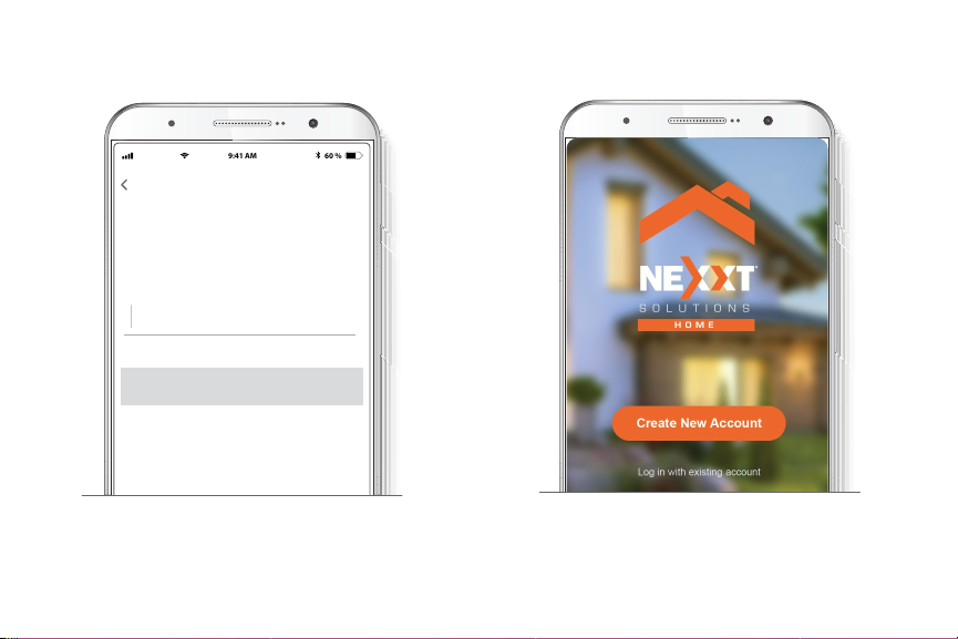
Login with existing account
Create New Account
SOLUTIONS
Iniciarsesión con cuenta existente
Crear Cuenta Nueva
SOLUTIONS
60 %
9:41 AM
Nexxt Home
Nexxt Solutions Home App
Cancel
INSTALL
Accvent LLC

Step 1
Register by email. Fill in the required elds.
60 %
9:41 AM
Register by email
United States of America
Email
Get authentication code
Step 2
Enter the verication code you received.
60 %
9:41 AM
Enter verication code
Verication code has been sent to your
Step 3
Create a new password and then select Completed.
60 %
9:41 AM
Set Password
Completed
6-20 characters, including letters and numbers
Step 4
The Nexxt Solutions Home App has been successfully
installed.
Indice
Lingue:
Altri manuali Nexxt Solutions Interruttore


