NI WSN-3214 Manuale utente

USER GUIDE AND SPECIFICATIONS
NI WSN-3214
NI Wireless Sensor Network 4-Channel, Quarter/Half/Full Bridge Input Node
This user guide describes how to use the NI WSN-3214 input node and lists its specifications. The
NI WSN-3214 is a four-channel, low-power, wireless quarter-bridge, half-bridge, and full-bridge device
that works with other NI WSN-32xx nodes and gateways to form a wireless sensor network. Figure 1
shows the NI WSN system components.
Figure 1. NI WSN System Components
1 NI WSN-32xx Nodes
2 NI 9792 WSN Real-Time Gateway
3 NI WSN-9791 Ethernet Gateway
4 NI CompactRIO Chassis
5 NI 9795 WSN C Series Gateway
6 PC Running NI Software
1
1
3
4
5
6
Or
Or

NI WSN-3214 User Guide and Specifications 2 ni.com
The NI WSN system receives and analyzes distributed sensor data through one or more NI WSN
gateways, up to 36 NI WSN nodes per gateway, and multiple PCs.
When you connect the NI WSN gateway, you can use a separate host PC running Windows, or a
NI CompactRIO chassis running NI LabVIEW Real-Time, to display measurement results, status
information, and to change the NI WSN gateway and NI WSN-3214 device settings.
Dimensions
Figure 2 shows the NI WSN-3214 device dimensions.
Figure 2. NI WSN-3214 Device Dimensions
Safety Guidelines
Operate the NI WSN-3214 device only as described in this user guide.
Hot Surface This icon denotes that the component may be hot. Touching this component may result
in bodily injury.
NI WSN Safety Information
The following section contains important safety information that you must follow when installing and
using NI WSN products.
Caution Do not operate the NI WSN product in a manner not specified in the user manual or
operating instructions. Product misuse can result in a hazard. You can compromise the safety
123.98 mm
(4.881 in.)
85.85 mm
(3.380 in.) 42.29 mm
(1.665 in.)
231.25 mm
(9.104 in.)
50.8 mm
(2.00 in.)
25.40 mm
(1.00 in.)
55.88 mm
(2.200 in.)

©National Instruments 3 NI WSN-3214 User Guide and Specifications
protection built into the product if the product is damaged in any way. If the product is damaged,
return it to National Instruments for repair.
Caution Do not substitute parts or modify the NI WSN product. Use the product only with the
devices, accessories, and cables specified in the installation instructions.
Caution Do not operate NI WSN products in an explosive atmosphere or where there may be
flammable gases or fumes.
Caution If you need to clean a NI WSN product, wipe it with a dry towel. The product must be
completely dry and free from contaminants before you return it to service.
Caution Operate the product indoors only at or below Pollution Degree 2. Pollution is foreign matter
in a solid, liquid, or gaseous state that can reduce dielectric strength or surface resistivity.
Caution You must insulate signal connections for the maximum voltage for which the NI WSN
product is rated. Do not exceed the maximum ratings for the product. Do not install wiring while the
product is live with electrical signals. Do not remove or add connector blocks when power is
connected to the NI WSN system. Avoid contact between your body and the connector block signal
wiring when hot-swapping devices.
Caution To comply with safety regulations, use only recommended batteries with this product.
Refer to the Battery Power section for the recommended battery types.
Safety Guidelines for Hazardous Locations
The NI WSN-3214 is suitable for use in Class I, Division 2, Groups A, B, C, D, T4 hazardous locations;
Class I, Zone 2, AEx nC IIC T4 and Ex nL IIC T4 hazardous locations; and nonhazardous locations
only. Follow these guidelines if you are installing the NI WSN-3214 in a potentially explosive
environment. Not following these guidelines may result in serious injury or death.
Caution Observe the battery manufacturers’ operating temperature ratings listed in the Battery
operating temperature range specification section.
Caution Do not disconnect the power supply wires and connectors from the device unless power has
been switched off.
Caution Do not install or remove the device unless power has been switched off.
Caution Substitution of components may impair suitability for Class I, Division 2.
Caution For Zone 2 applications, install the WSN system in an enclosure rated to at least IP 54 as
defined by IEC 60529 and EN 60529.
Special Conditions for Hazardous Locations Use in Europe
The NI WSN-3214 has been evaluated as Ex nA nL IIC T4 equipment under DEMKO Certificate No. 07
ATEX 0626664X. Each module is marked II 3G and is suitable for use in Zone 2 hazardous
locations, in ambient temperatures of –40 °C ≤Ta ≤70 °C.
Electromagnetic Compatibility Guidelines
This product was tested and complies with the regulatory requirements and limits for electromagnetic
compatibility (EMC) as stated in the product specifications. These requirements and limits are designed
to provide reasonable protection against harmful interference when the product is operated in its
intended operational electromagnetic environment.

NI WSN-3214 User Guide and Specifications 4 ni.com
This product is intended for use in industrial locations. There is no guarantee that harmful interference
will not occur in a particular installation, when the product is connected to a test object, or if the product
is used in residential areas. To minimize the potential for the product to cause interference to radio and
television reception or to experience unacceptable performance degradation, install and use this product
in strict accordance with the instructions in the product documentation.
Furthermore, any changes or modifications to the product not expressly approved by National
Instruments could void your authority to operate it under your local regulatory rules.
The following statements contain important EMC information needed before installing and using this
product:
Caution To ensure the specified EMC performance, product installation requires either special
considerations or user-installed, add-on devices. See the product installation instructions for further
information.
Caution To ensure the specified EMC performance, operate this product only with shielded cables
and accessories.
Caution To ensure the specified EMC performance, operate this product with a DGND terminal on
the I/O connector tied to earth ground or use the NI recommended external power supply
(NI part number 780703-01) or equivalent.
Caution The inputs/outputs of this product can be damaged if subjected to Electrostatic Discharge
(ESD). To prevent damage, industry-standard ESD prevention measures must be employed during
installation, maintenance, and operation.
This product may become more sensitive to electromagnetic disturbances in the operational
environment when test leads are attached or when connected to a test object.
Related Documentation
Check ni.com/manuals for the most recent documentation. For a complete list of documentation
related to the NI WSN system, refer to ni.com/info and enter rdwsnrd.
In addition to this guide, the following documents may be useful when configuring your NI WSN
system:
• The getting started guide for your NI WSN gateway(s)
• The user guide and specifications for your NI WSN node(s)
•Configuring WSN in MAX, available from Start»All Programs»National Instruments»
NI-WSN LabVIEW Help for WSN Devices, available in LabVIEW from Help»LV Help»WSN
Devices Help
•NI-WSN Readme, available on the software installation disc included with your gateway
Training Courses
If you need more help getting started developing an application with NI products, NI offers training
courses. To enroll in a course or obtain a detailed course outline, refer to ni.com/training.
Technical Support on the Web
For additional support, refer to ni.com/support or zone.ni.com.

©National Instruments 5 NI WSN-3214 User Guide and Specifications
Software Overview
Note Refer to the NI-WSN Readme, available on the software installation disc included with your
gateway or at ni.com/drivers, for NI software application version support.
The NI-WSN software is supported by Windows 7/Vista/XP and contains the following components:
• NI Measurement & Automation Explorer (MAX)
• NI-WSN
NI-WSN software and NI MAX manage the hardware configurations and simplify programmatic access
to I/O channels. The NI-WSN software is downloadable from ni.com/drivers and on the software
installation disc included with your NI WSN gateway. You can download a current version of NI-WSN
software from ni.com/support. Using your Web browser, go to ni.com/support and select Drivers
and Updates»Distributed I/O»Wireless Sensor Networks, and then select the latest version of
NI-WSN software. If you are using other software, refer to the accompanying installation instructions.
What You Need to Get Started
To set up and use NI LabVIEW with the NI WSN-3214 device, you need the following:
•NIWSNgateway
• NI WSN-3214 device(s) with a 5–30 V power supply or four alkaline or lithium AA 1.5 V batteries
for each node. Refer to the Battery Power section for recommended battery types.
• Mounting hardware (DIN rail or panel-panel mount)
• Ethernet cable/connection
• 1/8 in. flathead and number 2 Phillips screwdrivers
• NI-WSN 1.3.1 or later
• Host PC running Windows 7/Vista/XP
• NI LabVIEW 2011 (32-bit) or later
• NI LabVIEW 2011 WSN Module or later (optional)
•(NI 9792 WSN Real-Time Gateway Only)—NI LabVIEW (32-bit) Real-Time Module or later
•(NI 9795 WSN C Series Gateway Only)—NI-RIO 4.0 or later and NI LabVIEW (32-bit) Real-Time
Module
• Related hardware and software documentation
For more information about NI-WSN software versions, go to ni.com/info and enter wsnsoftware.
Unpack the Device and Install the Antenna
Remove the device from the package and inspect the device. Contact NI if the device appears damaged.
Do not install a damaged device.
Caution The device is static sensitive. Always properly ground yourself and the equipment when
handling or connecting to the device.
Caution An electrostatic discharge (ESD) to the antenna connector when the product is operating
may cause interference or disruption of the wireless signal. To prevent ESD, do not attempt to remove
the antenna while the product is operating or ensure that you employ industry-standard ESD
prevention measures.
Caution The antenna must be attached to the NI WSN device in order for the NI WSN device to
function correctly.

NI WSN-3214 User Guide and Specifications 6 ni.com
To attach the antenna, align the antenna with the mount and screw it on, as shown in Figure 3.
Figure 3. Attach the Antenna to the Device
Mounting the NI WSN-3214 Device
You can mount the NI WSN-3214 on a panel or on a 35 mm DIN rail. For kit accessory ordering
information, refer to the NI WSN product page accessory section at ni.com. Before using any of these
mounting methods, remove and save the serial number sticker located on the back of the NI WSN-3214
device for future use when configuring your device in the software. For the NI WSN-3214 device
dimensions, refer to Figure 2.
Caution Your installation must allow 50.8 mm (2 in.) of clearance in front of the device for common
connector cabling, such as the 36-terminal detachable screw terminal connector.
Attaching the NI WSN-3282 DIN Rail (Optional)
You can mount the NI WSN-3214 on a standard 35 mm DIN rail using a NI WSN-3282 DIN rail clip,
NI part number 781074-01. Complete the following steps to mount the NI WSN-3214 on a DIN rail:
Caution Power off the device before mounting it to the DIN rail.
Note Use thread-forming screws to permanently affix the DIN rail clip to the device. Unscrewing
and reinstalling the thread-forming screws produces a compromised connection between the DIN rail
clip and the device.
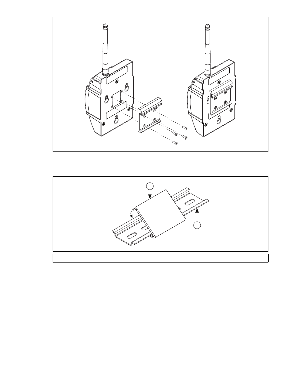
1. Fasten the DIN rail clip to the NI WSN-3214 using a number 2 Phillips screwdriver and the
four 8-32 ×5/16 in. thread-forming screws that shipped with the DIN rail clip(s). Figure 4 shows
how to fasten the DIN rail clip to the NI WSN-3214.
Caution Do not use screws longer than 5/16 in. to fasten the DIN rail clip to the NI WSN-3214.
NATIONAL
INSTRUMENTS
NATIONAL
INSTRUMENTS

©National Instruments 7 NI WSN-3214 User Guide and Specifications
Figure 4. NI WSN-3214 Device DIN Rail Installation
2. Insert one edge of the DIN rail into the deeper opening of the DIN rail clip, as shown in Figure 5.
Figure 5. DIN Rail Clip Installation
3. Press down firmly on the NI WSN-3214 to compress the spring until the clip locks into place on
the DIN rail.
1 DIN Rail Clip (Without Device) 2 DIN Rail
2
1

NI WSN-3214 User Guide and Specifications 8 ni.com
Using a Panel Mount Accessory
The NI WSN-3280/3281 panel mount accessories, NI part numbers 780999-01 and 781073-01, each
include a retention clip and knob and integrated strain relief for power and I/O wires. You can use the
NI WSN-3280 panel mount accessory to attach the NI WSN-3214 device to a panel or other flat
surface. The NI WSN-3281 panel mount accessory also includes a magnetic mount for attaching the
NI WSN-3214 device to metallic surfaces. Figure 6 shows the NI WSN-3214 panel mounting
dimensions.
Figure 6. NI WSN-3214 Device Panel Mount Dimensions
78.74 mm
(3.100 in.)
4.5 mm
(5× Ø.177 in.)
44.02 mm
(1.733 in.)
183.79 mm
(7.236 in.)
55.88 mm
(2.200 in.)
13.97 mm
(0.550 in.)
25.40 mm
(1.000 in.)
25.40 mm
(1.000 in.)
53.34 mm
(2.100 in.)

©National Instruments 9 NI WSN-3214 User Guide and Specifications
Figure 7. Panel Mount Accessory
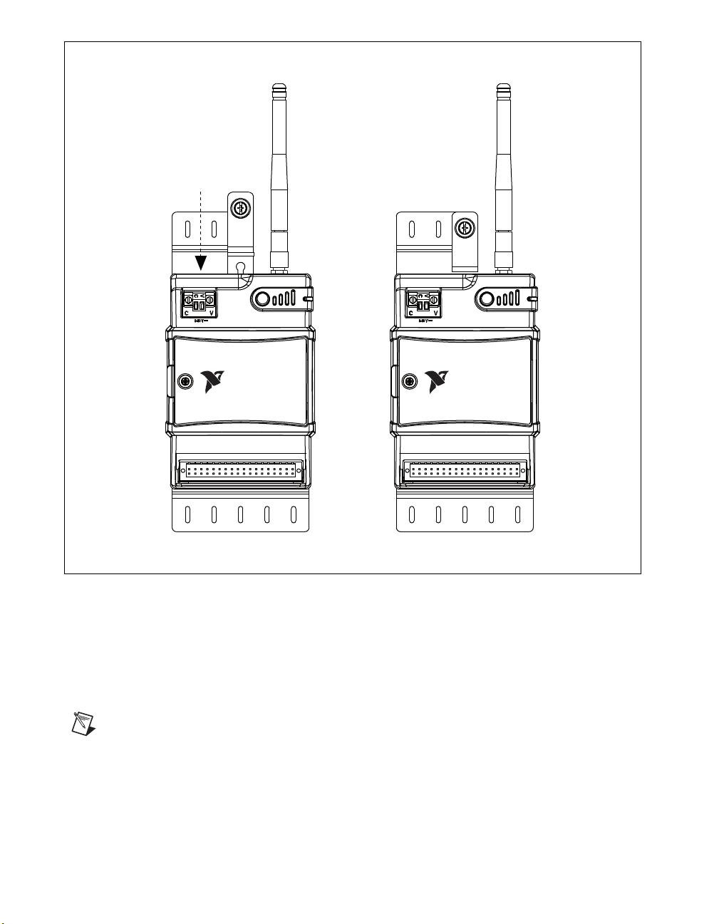
Refer to Figure 7 while completing the following steps to mount the NI WSN-3214 on a panel:
1. (NI WSN-3280) Bolt or screw the panel mount accessory to a panel using five 8-32 or M4 screws.
(NI WSN-3281) Attach the panel mount accessory using the integrated magnet.
2. Slide the NI WSN-3214 device into the panel mount accessory, as shown in Figure 7.
3. Slide the retention clip down and tighten the panel mount knob to secure the NI WSN-3214 device,
as shown in Figure 8.
4. (Optional) Secure any I/O signal or power supply cabling to the panel mount accessory using a
zip-tie and the integrated strain relief slots.
1 Retention Knob
2 Retention Clip
3 Mounting Hole
4 Integrated Mounting Pin
5 Power and I/O Strain Relief
NATIONAL
INSTRUMENTS
1
5
4
2
3
5

NI WSN-3214 User Guide and Specifications 10 ni.com
Figure 8. Slide Retention Clip Down and Tighten Panel Mount Knob
Using the Integrated Panel Mount Slots
You can also mount the NI WSN-3214 to a panel using the integrated panel mount slots, as shown in
Figure 9.
1. Attach three number 8 or M4 pan head screws in the mounting panel, leaving 0.1 in. space under
the head of each screw. Refer to Figure 2 for the correct hole pattern and dimensions.
2. Slide the NI WSN-3214 device onto the panel.
Note In this configuration, the NI WSN-3214 is held in place only by the weight of the device and
the friction of the screw attachment. Use the DIN rail clip or panel mount accessories in high
vibration environments.
NATIONAL
INSTRUMENTS
NATIONAL
INSTRUMENTS
Indice
Altri manuali NI Sistema I/O
Manuali Sistema I/O popolari di altre marche

WAGO
WAGO 750-344 Manuale utente

Teknim
Teknim TWM-1887 Manuale di istruzioni

Intelligent Appliance
Intelligent Appliance IA-2662-E Manuale utente

BERGHOF
BERGHOF ECC DIO 16/16 Manuale di istruzioni

Advantech
Advantech PCM-27J3AU Manuale di installazione e funzionamento

Festo
Festo CP-E08-M12-CL Manuale utente