Sensors etc.
Internal
FunctionLocationName
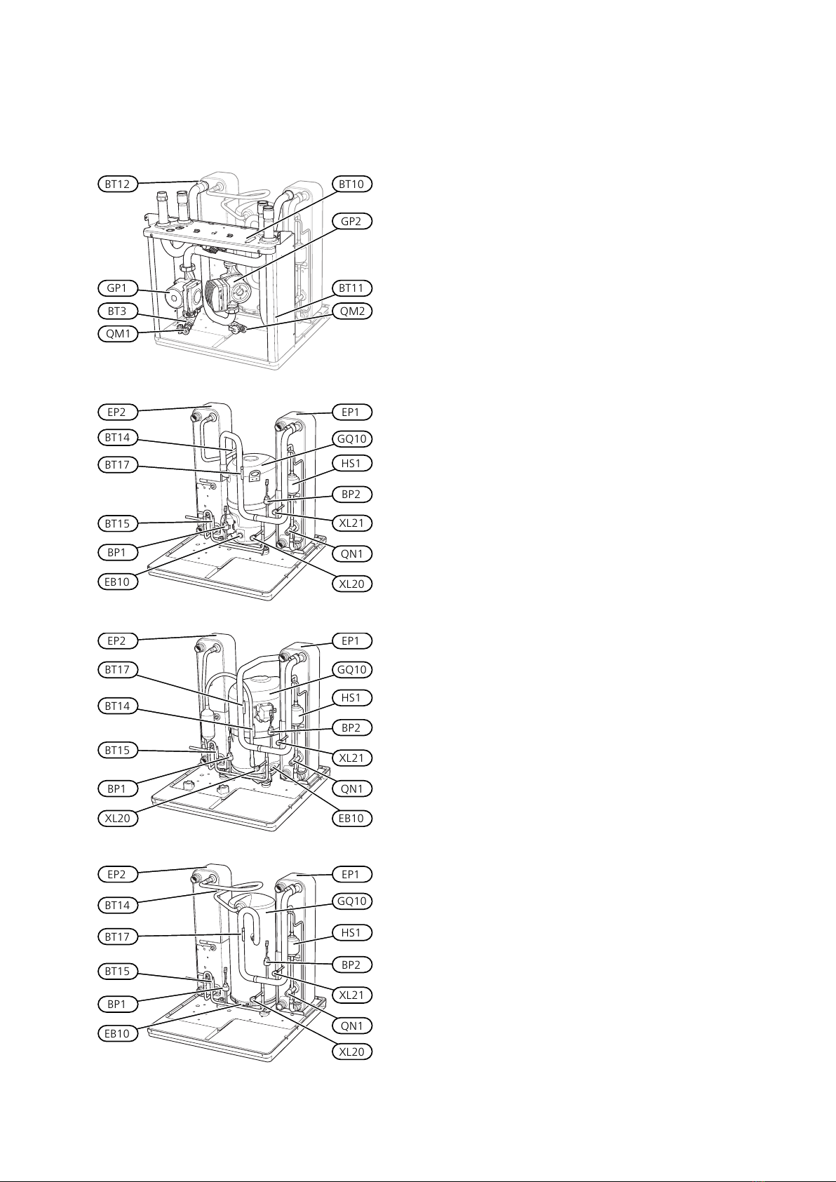
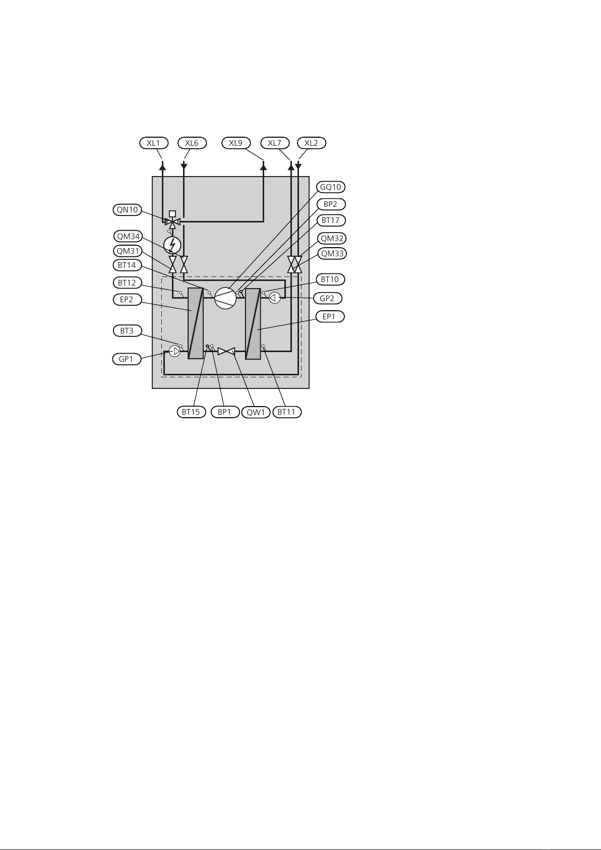
Protects the compressor against pres-
sures that are too high.
On the liquid line.High pressure pressostatBP1
Protects the compressor against pres-
sures that are too low.
On suction gas line.Low pressure pressostatBP2
Set point values for heating and cool-
ing demand calculation. Operating
mode change.
Outdoor, shaded location on north side
of the house.
Outside sensorBT1*
Calculation of DM. If BT25 is installed,
only view.
On supply line after immersion heater
(EB1).
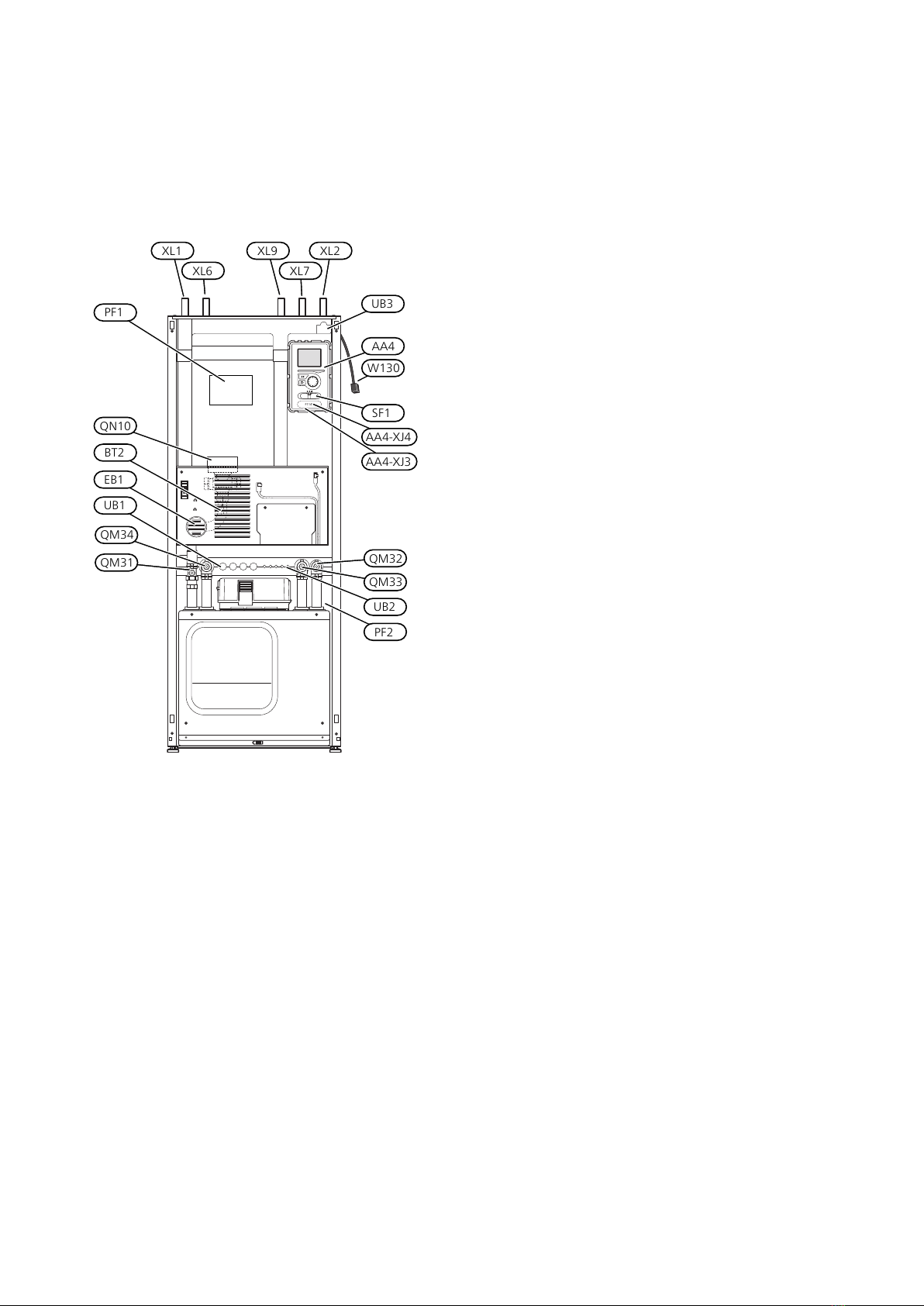
Flow pipeBT2
Stopping the compressor at high tem-
perature.
On return line between circulation
pump (GP1) and condenser (EP2).
Return pipeBT3
Stop and start of hot water charging.On water heater lower section.Hot water, chargingBT6*
Also used for display if BT7 is not in-
stalled.
View.At water heater peak.Hot water, topBT7*
View.On incoming brine line before circula-
tion pump (GP2).
Brine inBT10
Stops compressor at high temperature.
Controls brine pump speed together
with BT11
Stopping the compressor at low tem-
perature.
On outgoing brine line after evaporator
(EP1).
Brine outBT11
Controls brine pump speed together
with BT10
Stopping the compressor at high tem-
perature.
On supply line between condenser
(EP2) and immersion heater (EB1).
Condenser flow lineBT12
Stopping the compressor at high tem-
perature.
On hot gas line after compressor
(GQ10).
DischargeBT14
View.On the liquid line after the condenser
(EP2).
Fluid pipeBT15
View.On suction gas line before the com-
pressor (GQ10).
Suction gasBT17
Calculation of DM. If BT25 is connected.Externally on the flow line to the heat-
ing system.
External flow lineBT25*
Correction of the indoor temperature.In suitable indoor location.Room sensorBT50*
* Externally mounted (not included in outline diagram).
NIBE F1126Chapter 3 | System description10