
Nitek ER8500U Manuale utente

Model ER16500U / ER8500U Installation and
Operation Manual
Introduction
The ER8500U and ER16500U are fully functional POE network switches with 802.3AT power output on each of the
network ports and can operate with all standard Ethernet devices up to 100 meters. Additionally, when used with the
ET1500U transmitter the system allows for cable runs of 600 meters or 2000 feet and will supply both a network
connection and POE power. The ER8500 has 8 network ports and 1 LAN port and the ER16500 has 16 network ports
and 2 LAN ports. Each of the network ports support standard Ethernet 10/100Mb network traffic and the LAN ports
support standard Ethernet 10/100/1000Mb network traffic. The LAN ports do not supply POE.
NITEK®
De Schans 19-21 2a
8231 KA Lelystad
Tel: +31(0)320-2300005
Fax: +31(0)320-282186
WWW.NITEK.NL
USA
5410 Newport Drive, # 24
Rolling Meadows, IL 60008
Phone: (847) 259-8900
Fax: (847) 259-1300
WWW.NITEK.NET
EUROPE
122911
2) Connect up the network outputs of the unit. The network ports are designed for connection with standard Ethernet
cables. The network ports are 10/100Mb speed and will run at the highest possible speed given the wire conditions.
This system normally operates at 100Mb over 600 meters of cable. We refer to the cable between the Head-end and
the transmitter as the Link cable. The speed of the connection is indicated on the network port of the unit. A
transmitter or other network device must be connected at the other end of the network cable for the connection speed
to be indicated.
681200114
Head-end Installation
ER8500U and ER16500U
1) The ER8500U / ER16500U can be rack mounted, wall mounted or used as desk top unit. Use the included mounting
ears in the front or back of the unit depending on your needs. The mounting ears can also be turned to the bottom of
the unit for wall mounting if needed. When mounting the unit be sure to leave space on the sides for airflow into the
cooling fans and some space on top of the unit for air to exit the unit.
Front
Back
Rack Mounting
Options Wall Mounting
Options
UTP Network Ports LAN Ports

3) Connect the LAN port to the network switch. The LAN ports of the ER8500 / ER16500 can communicate at up to
1Gbps each. The LAN port will automatically sense the connection speed of the network switch. The LAN port is NOT
POE capable, only the network ports can provide power to connected devices. The LAN port of the ER8500 /
ER16500 will gather data from the network ports and combine it into the higher speed LAN port. The data speed and
POE status for all connected ports is indicated on the port LEDs. Make sure your network switch can handle the ex-
pected data (i.e. do not use a 100Mb network switch if you expect 300Mbps of data).
4) Connect main power to the ER8500 / ER16500 using a proper IEC power cord. A power cord is supplied in the box
with your ER8500 / ER16500 unit.
5) After completing the installation of the Head-end equipment, transmitter units must be installed at the camera/remote
end.
Simplified System Hookup Diagram
115/230
VAC
ET1500
ET1500
Network Switch,
NVR or Server
Link Cable
Up to 2000 feet / 600m
Cat5 or better cable
Front Panel LED Display
POE OUT
Network Connection
Green = 100Mb
Orange = 10Mb
Network Connection /
Green = 1Gb
Yellow = 100Mb
Orange = 10Mb
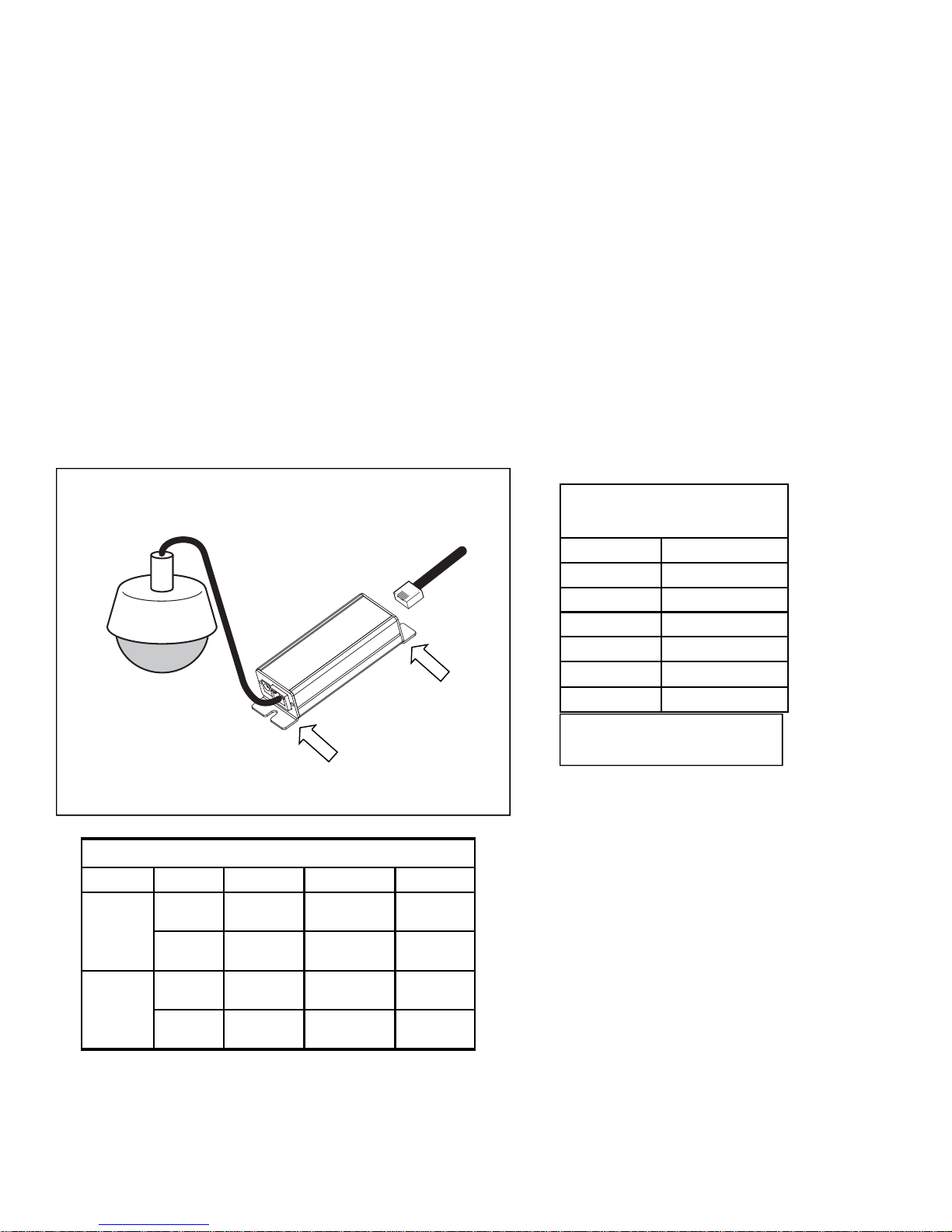
Transmitter-end Installation
ET1500U Units
6) At the camera location securely mount the transmitter.
7) Find the Link cable from the head-end and make sure it is properly terminated. Connect Link cable to the “Link Port” of
the transmitter. If the head-end unit is powered up it will sense the connection to the transmitter and turn on the
power. This will be indicated by the green POWER LED on the “Network Port”. After about 15 to 30 seconds the or-
ange 10/100Mb LED on the “Link Port” will turn-on to tell you that the system is connected. An Ethernet device does
not need to be connected for the transmitter to communicate with the head-end.
8) Finally, connect an Ethernet device to the transmitters “Network Port”. If the device requires PoE power, the POE
OUT, green LED on the “Link Port” will turn on followed by the LINK STATUS LED on the “Network Port”. The IP
camera or other Ethernet device should now be ready to operate. Continue installing the remaining transmitters as
needed.
Connector LED OFF ON FLASHING
Network
Port
Power No power Power
Good
Link
Status No Ethernet
Link Ethernet Link
Good
Link
Port
PoE Out No PoE
Power Out PoE Power
Good
10/100 No Link 100Mb 10Mb
LED INDICATORS
ET1500
IP Camera
Cable from
Head-end
Transmitter Hookup Diagram
Link Port
Network Port
PoE Device Power
4 pair CAT5+ *
Distance Power at PoE Port
325ft/100m 30 watts
1000ft/300m 20.5 watts
1300ft/400m 19.1 watts
1600ft/500m 18.3 watts
650ft/200m 21.5 watts
2000ft/600m 17.2 watts
*Results with ER8500 Receiver and
using 4 pair CAT5+ cable

Optional Hookup for High Power PoE Devices
ET1500U Units
9) In some cases the PoE device connected to the transmitter needs more power than can be supported over a long ca-
ble run. You can usually identify these cases by watching the POWER LED of the transmitter, located on the
“Network Port”. If the power light cycles ON for less then 1 second and then is off for 3 or 4 seconds when the PoE
device is connected, but it turns ON and operates normally without a PoE device connected, this would indicate you
are having a current limit problem.
10) You should first check the power requirements of the PoE device. Also check the length of the Link cable from head-
end to transmitter. The POE POWER CHART on the previous page will indicate the maximum power available for
your length of cable.
11) If the needed level of power is not available for the length of cable, used alternate options are available. One method
is to directly power the transmitter with a 48VDC power supply as shown below (Nitek# PS48). When powered di-
rectly from a 48VDC supply the transmitter can deliver full 802.3AT power regardless of the cable length plus an ad-
ditional length of up to 100 meters of network cable.
Distance from
Network Port PoE Device Power
Available
30ft/10m 33 watts
325ft/100m 26 watts
Transmitter used as
PoE Injector*
*Results with 48VDC power to the
Transmitter optional Power Port
ET1500
PS48
IP Camera
Cable from
Head-end
48VDC Powered Transmitter Hookup Diagram
Link Port
Network
Port
115 VAC
Optional
48VDC
Supply
Altri manuali per ER8500U
1
Questo manuale è adatto per i seguenti modelli
1
Indice
Altri manuali Nitek Interruttore


