Nordyne C8DA Series Manuale utente
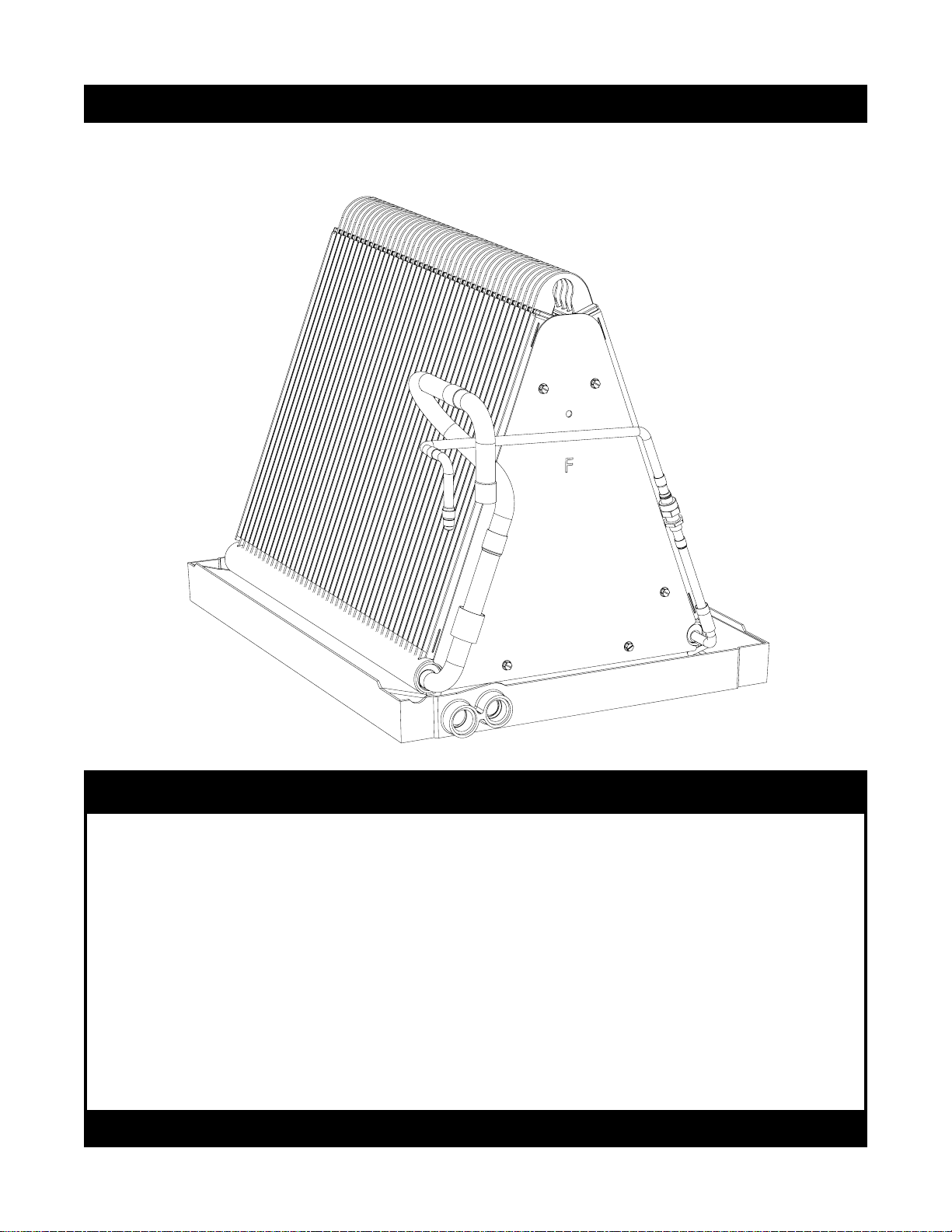
C8DA Series Split System Uncased Indoor Coils - Downturn
INSTALLATION INSTRUCTIONS
DO NOT DESTROY. PLEASE READ CAREFULLY AND KEEP IN A SAFE PLACE FOR FUTURE REFERENCE.
IMPORTANT
ATTENTION INSTALLERS:
It is your responsibility to know this product better than your customer.This includes being
abletoinstalltheproduct accordingtostrictsafetyguidelinesandinstructingthecustomeron
how to operate and maintain the equipment for the life of the product.Safety should always be
the deciding factor when installing this product and using common sense plays an important
role as well.Pay attention to all safety warnings and any other special notes highlighted in the
manual. Improper installation of the furnace or failure to follow safety warnings could result
in serious injury, death, or property damage.
These instructions are primarily intended to assist qualified individuals experienced in the
proper installation of this appliance. Some local codes require licensed installation/service
personnel for this type of equipment. Please read all instructions carefully before starting the
installation. Return these instructions to the customer’s package for future reference.
2
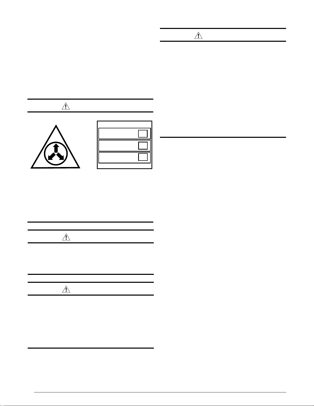
IMPORTANT SAFETY INFORMATION
Pleasereadallinstructionsbeforeservicingthisequipment.
Payattentiontoall safetywarningsandany otherspecial
notes highlighted in the manual. Safety markings are
used frequently throughout this manual to designate a
degreeorlevelofseriousnessandshouldnotbeignored.
WARNINGindicatesapotentiallyhazardoussituationthat
if not avoided, could result in personal injury or death.
CAUTIONindicatesapotentiallyhazardoussituationthat
if not avoided, may result in minor or moderate injury or
property damage.
WARNING:
PROPOSITION 65 WARNING: This product
contains chemicals known to the state of
Californiatocausecancer,birthdefectsorother
reproductive harm.
WARNING:
Improper installation, service, adjustment,
or maintenance may cause explosion, fire,
electricalshockorotherhazardousconditions
whichmayresult in personalinjuryorproperty
damage. Unless otherwise noted in these
instructions, only factory authorized kits or
accessories may be used with this product.
WARNING:
C8DAcoilsarepressurizedwithNitrogenatthe
factory. Avoid direct face exposure or contact
withvalvewhengasisescaping.Alwaysensure
adequate ventilation is present during the
depressurization process. Any uncertainties
should be addressed before proceeding.
NITROGEN
HEALTH
FLAMMABILITY
REACTIVITY
0 Minimal Hazard 1 Slight Hazard
1
0
0
WARNING:
This unit must be installed in accordance
with the instructions outlined in this manual
during the installation, service, and operation
of this unit. Unqualified individuals should
not attempt to interpret these instructions or
install this equipment. If you do not posses
mechanicalskillsortools,callyourlocaldealer
forassistance.Undernocircumstancesshould
the equipment owner attempt to install and/or
service this equipment.Failure to follow safety
recommendations could result in possible
damage to the equipment, serious personal
injury or death.
• The installer must comply with all local codes and
regulations which govern the installation of this type
of equipment. Local codes and regulations take
precedence over any recommendations contained in
these instructions. Consult local building codes for
special installation requirements.
• Familiarizeyourselfwiththecontrolsthatshutoffthe
electrical power to the unit. If the unit needs to be shut
down for an extended period of time, turn off electrical
power at the circuit breaker. For your safety always
turn off the electrical power before performing service
or maintenance on the unit.
• Installationofequipmentmayrequirebrazingoperations.
Installer must comply with safety codes and wear
appropriate safety equipment (safety glasses, work
gloves,fireextinguisher,etc.)whenperformingbrazing
operations.
• Read the Installation Instructions supplied with the
furnace or air handler. Always observe all safety
requirementsoutlinedinthismanualandonthefurnace
or air handler markings before installing the coil.
• Follow all precautions in the literature, on tags, and
on labels provided with the equipment. Read and
thoroughly understand the instructions provided with
the equipment prior to performing the installation and
operational checkout of the equipment.
3
GENERAL INFORMATION
C8DA series coils are designed for upflow or downflow
applicationsandareequippedwithdownturnedrefrigerant
connections and are ready for brazing.
• Checkthecoilsoricesizeandconrmthatit’ssuitable
forapplicationwiththeintendedoutdoorunit.Depending
on application, additional installer supplied orifice or
TXVmayberequired.
• Optional cooling/heating equipment must be
properly sized and installed in accordance with the
furnace manufacturer’s specications and approved
recommendations.
• Heating only furnace air circulators may have to be
replacedwithmulti-speedHeating/Coolingblowersto
upgradetheairdelivery(CFM)whenanadd-oncoilis
installed.RefertoTable1(page6)forcoilspecications,
recommendedCFM,andallowancesforpressuredrop
across the coil and filters.
• Verifythattheairdeliveryofthefurnace/airhandleris
adequate to handle the static pressure drop of the coil,
filter, and duct work.
• Ifpreciseformingofrefrigerantlinesisrequired,acopper
tubingbenderisrecommended.Avoidsharpbendsand
contact of the refrigerant lines with metal surfaces.
• Refrigerant lines should be wrapped with pressure
sensitive neoprene or other suitable material where
they pass against sharply edged sheet metal.
• Thecoilenclosure(ifprovided)andsuctionlinemust
be insulated as needed to prevent condensate from
forming and causing property damage.
• Do not remove seals from the coil until the tubing
connections are ready to be made.
• Close-off plates are available in some air lter kits.
RefertotheReplacementPartsListforavailablepart
numbers. Install the necessary close-off plates around
the refrigerant lines and drain line where required.
Reinstallallinnerandouterpanelsofthefurnace/air
handler that were previously removed when installing
the indoor coil.
COIL INSTALLATION
WARNING:
ELECTRICAL SHOCK, FIRE OR EXPLOSION
HAZARD
Failure to follow safety warnings exactly could
result in serious injury or property damage.
Improper servicing could result in dangerous
operation, serious injury, death or property
damage.
to the furnace and outdoor condensing unit.
to disconnecting. Reconnect wires correctly.
CAUTION:
The coil must be level to ensure proper
condensate drainage. An unlevel installation
may result in structural damage, premature
equipment failure, or possible personal injury.
Upflow Installations
1.Disconnectallelectricalpowertothefurnace.
2.Installthecoilcaseonthefurnaceairdischargeopening
and level it as needed to ensure proper condensate
drainage. If needed, make a plate to adapt the coil to
theairdischargeopening.SeeFigure5(page6)for
coil dimensions.
3.Makeandinstalltheplenumoverthecoil.Insulateas
required.
4.Seal theenclosure asrequired tominimizeairleakage.
5.Connect the refrigerant lines as outlined in the
RefrigerantLineConnectionsection.
Downflow Installations
Thesecoilsmaybeinstalledindownowapplications.It
isrequiredthatthe furnaceandcoil cabinetsaresecurely
mounted together before setting in place. Fossil fuel
applications require the coil to be placed in the supply
air stream only.
Refrigerant Line Connections
System Depressurization
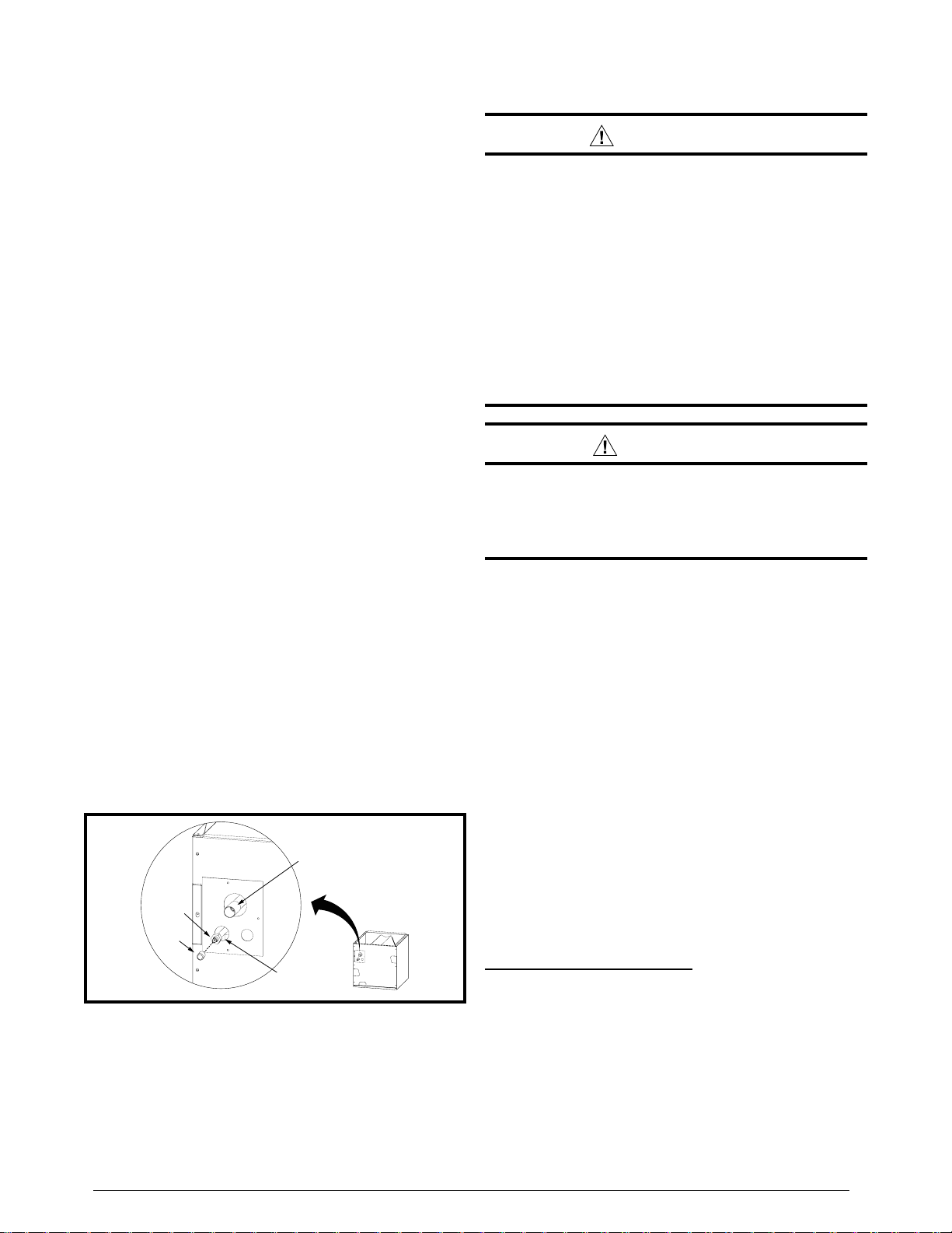
1.Removethecap(Figure1)fromtheendoftheliquid line.
2.VerifypressurizationbydepressingtheSchradervalve
ontheendoftheliquidline.Listenforanyescapinggas.
If there is no pressure, test the coil for leakage.
• Ifleakageisfound,clearlymarkthelocationofthe leak
and return the coil to the distributor for processing.
• Ifnoleaksarefound,thecoilmaybeinstalled.
3.Depress the valve to relieve all pressure from the coil.
Suction
Line
Liquid
Line
Cap
Schrader
Valve
Figure 1. Suction & Liquid Line Locations
4
OriceRemoval&Installation
NOTE:Beforeproceeding,performsteps1-3intheSystem
Depressurization section and confirm that the restrictor orifice
size meets the requirements outlined in the outdoor unit
installation manual.
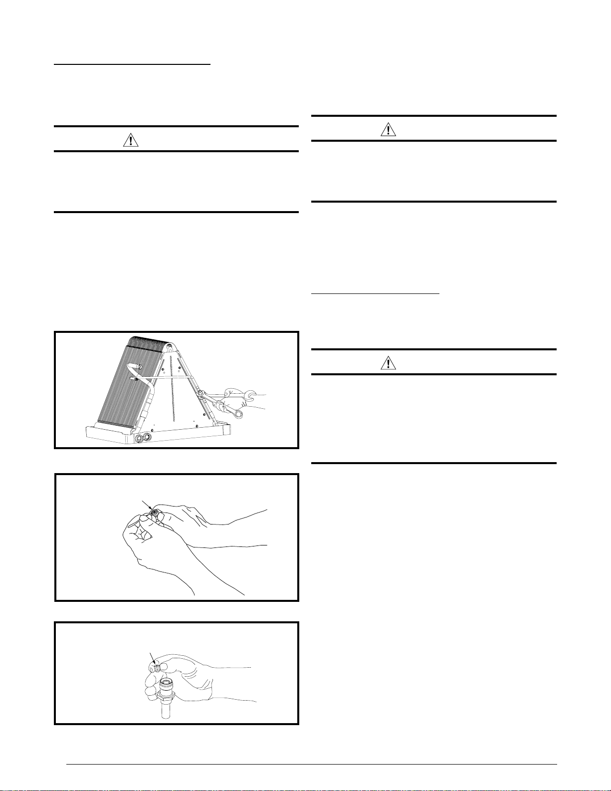
CAUTION:
To prevent damage to the unit or internal
components, it is recommended that two
wrenchesbeusedwhenlooseningortightening
nuts. Do not over tighten!
1.Usingtwowrenches,loosenthenutanddistributorbody
asshowninFigure2.Turntheassemblynutcounter-
clock-wise until the orifice body halves are seperated.
2.Insert a light-gauge wire hook between the distributor
body and the restrictor orifice while being careful not
to scratch either part. Carefully remove the restrictor
oricefromthedistributorbody.SeeFigure3.Factory
suppliedoricesizesarelistedinTable1(page6).If
theoricemustbereplaced,followsteps1-5
Install restrictor with
rounded end down
in the distributor
Figure 3. Removal of Orifice
Carefully remove the
restrictor orifice from
the distributor body
3.Checkthe actual sizeof the neworice.Thesizeis
stampedon itsside.Donotuse pin gaugesto measure
the orifice diameter.
4.Insert the new orifice into the distributor body, rounded
enddown.SeeFigure4.
CAUTION:
To prevent damage to the unit or internal
components, it is recommended that two
wrenchesbeusedwhenlooseningortightening
nuts. Do not over tighten!
5.Realigntheassemblynutonthedistributorbodyand
hand tighten both components. Mark a line on both
bodiesandthentightenanadditional1/4turnusingtwo
wrenches.Themovementofthetwolineswillshowhow
much the nut is tightened. If a torque wrench is used,
tightento10-12ft.lbs.or14-16Nm.
Connecting the Linesets
1.Routeandcut bothlineset tubesto properlength in
accordancewiththeoutdoorunitspecications.Verify
the ends are round, clean, and free of any burrs.
2.Connect the suction and liquid lineset tubes.
CAUTION:
It is recommended that a wet rag be wrapped
around the suction line in front of the close
off plate before applying heat. Failure to keep
components cool during brazing may result
in structural damage, premature equipment
failure, or possible personal injury.
3.Brazetheindividualconnectionswithdrynitrogenflowing
throughthejoints.Thiswillpreventinternaloxidation
and scaling from occurring.
IMPORTANT:Topreventinternaloxidationandscaling
fromoccuring,brazeallconnectionswithdrynitrogen
flowing through the joints.
4.Wrap the refrigerant lines with pressure sensitive
neoprene or other suitable material especially where
the lines enter the opening in the sheet metal.
5.Evacuatethesystemofmoistureandnon-condensables
to prevent low efficiency operation or damage to the
unit.Thesuggestedrangeofevacuationis250-500
microns.
6.Chargethesystemwithrefrigerant.Please Refer to
the outdoor unit installation manual for additional
charging instructions.
7.Checkthesystemforleaks,includingthelinesetandthe
brazedjoints.NOTE:Applyasoapandwatersolutionon
each joint or union with a small paintbrush. If bubbling
is observed, the connection is not adequately sealed.
8.Properly dispose of all removed parts.
5
Condensate Drain
CAUTION:
The coil must be level to ensure proper
condensate drainage. Improper condensate
disposal may result in structural damage,
premature equipment failure, or possible
personal injury.
• Methodsfordisposingofcondensatevaryaccording
tolocalcodes.Refertolocalcodesorauthorityhaving
jurisidiction for restrictions and proper condensate
disposal requirements.
• Allcondensatepanshaveprimaryandsecondarydrain
connectionstomeetFHArequirements.Iftheapplication
is located in or above a living space where damage
mayresultfromcondensateoverow,aseparate3/4
inch drain must be provided from the secondary drain
connectionandasecondarydrainpanmustbeinstalled
undertheentireunit.Runsecondarydrainlinestoa
place where they are noticeable if used.
• The coil condensate pan is designed with 3/4”
NPSC drain connections. Use a PVC or similar
material fitting to attach the drain line to the pan.
NOTE: The tting should be hand tightened only.
Overtightening may crack the drain pan and cause
condensate to leak.
• The drain pan MUST be drained with eld supplied
tubing and looped to form a trap.
IMPORTANT: Failure to install a trap may result in
condensation overflowing the drain pan, resulting
in substantial water damage to surrounding area.
• Primethetrapwithwater.Insulatethedrainifitislocated
inanunconditionedspace,andtestthecondensateline
forleaks. Consult local codes for additional restrictions
or precautions.
• Routethelinestoasuitabledrain,avoidingsharpbends
andpinchingofthelines.Thedrainshouldmaintaina
minimum horizontal slope in the direction of discharge
ofnotlessthan1”verticalforevery10ftofhorizontal
run.
• During system checkout, inspect the drain line and
connections to verify proper condensate drainage.
WARNING:
ELECTRICAL SHOCK, FIRE OR EXPLOSION
HAZARD
Failure to follow safety warnings exactly could
result in serious injury or property damage.
Improper servicing could result in dangerous
operation, serious injury, death or property
damage.
power to the furnace and outdoor condensing
unit.
to disconnecting. Reconnect wires correctly.
CAUTION:
Do not operate the system without a suitable
filter in the return air duct system. Always
replace the filter with the same size and type.
Toensureoptimumperformanceandtominimizepossible
equipmentfailure,thefollowingmaintenancetasksshould
be performed periodically on this equipment:
1.Theairlterinstalledwiththesystemshouldbechecked
and cleaned or replaced twice per year.
2.Check the coil, drain pan, and condensate drain line
for cleanliness at the start of each heating and cooling
season. Clean as needed.
Air Filter
Air filters are not supplied as an integral part of this
coil; however, an air lter kit is available. Refer to the
ReplacementPartsListforavailablepartnumbers.
The lter must be installed upstream of the coil and
inspected frequently. When the filter becomes clogged
with dust or lint, it should be replaced (disposable type)
orcleaned(washabletype).Itisrecommendedthatfilters
be inspected and replaced at least twice during the year.
Generally it is best to replace or clean the filters at the
start of each heating and cooling season.
6
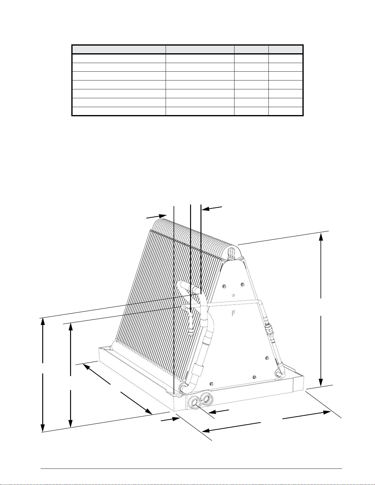
Figure 5. C8DA Coil Dimensions
2 1/2”
W
19 1/2”
1 3/8” 1”
12 1/8”
14 1/2”
H
Table 1. Coil Specifications
C8DA- 01830 036 042
NominalCapacity(BTUH) 18,000-30,000 36,000 42,000
NominalAirow(CFM) 600-1,000 1,200 1,400
W - Width (in.) 181/8 181/8 181/8
H-Height(in.) 18 18 243/4
Connection - Liquid Line (in.) 3/8 3/8 3/8
Connection - Suction Line (in.) 3/4 3/4 3/4
InstalledOriceSize(in.) .061 .067 .071
NOTES:
1. Individualrestrictorsareavailablebypartnumber-PN664***(where***representsthesize).
Example:664103isarestrictor0.103indiameter.
2. RefertosalesspecicationsheetsforListed/Certiedcombinationsofequipmentandrequiredaccessories.
3. RefertothecurrentAHRIdirectoryforcertiedratingsofsplitsystems.
COIL SPECIFICATIONS & DIMENSIONS

7
Specications&illustrationssubjecttochangewithoutnoticeorincurringobligations.
O’Fallon,MO|PrintedinU.S.A.(02/12) 709279A (Replaces7092790)
INSTRUCTIONSWITHTHE EQUIPMENT OWNER.
Questo manuale è adatto per i seguenti modelli
3
Indice
Altri manuali Nordyne Attrezzature industriali


