
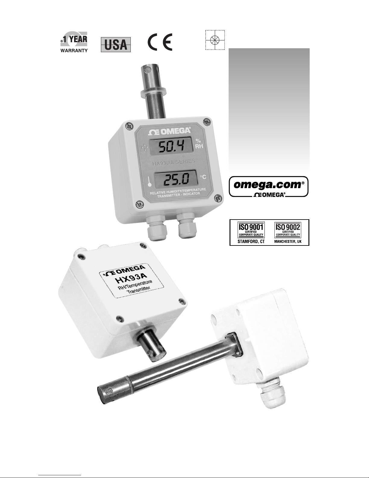
Omega Engineering RH/Temperature Transmitter HX93A Manuale utente
MADE IN
Shop online at

Servicing North America:
USA: One Omega Drive, Box 4047
ISO 9001 Certified Stamford CT 06907-0047
Tel: (203) 359-1660 FAX: (203) 359-7700
e-mail: [email protected]
Canada: 976 Bergar
Laval (Quebec) H7L 5A1, Canada
Tel: (514) 856-6928 FAX: (514) 856-6886
e-mail: [email protected]
For immediate technical or application assistance:
USA and Canada: Sales Service: 1-800-826-6342 / 1-800-TC-OMEGA®
Customer Service: 1-800-622-2378 / 1-800-622-BEST®
Engineering Service: 1-800-872-9436 / 1-800-USA-WHEN®
TELEX: 996404 EASYLINK: 62968934 CABLE: OMEGA
Mexico: En Espan˜ol: (001) 203-359-7803 e-mail: [email protected]
Servicing Europe:
Benelux: Postbus 8034, 1180 LA Amstelveen, The Netherlands
Tel: +31 (0)20 3472121 FAX: +31 (0)20 6434643
Toll Free in Benelux: 0800 0993344
e-mail: [email protected]
Czech Republic: Frystatska 184, 733 01 Karvina´, Czech Republic
Tel: +420 (0)59 6311899 FAX: +420 (0)59 6311114
France: 11, rue Jacques Cartier, 78280 Guyancourt, France
Tel: +33 (0)1 61 37 2900 FAX: +33 (0)1 30 57 5427
Toll Free in France: 0800 466 342
e-mail: [email protected]
Germany/Austria: Daimlerstrasse 26, D-75392 Deckenpfronn, Germany
Tel: +49 (0)7056 9398-0 FAX: +49 (0)7056 9398-29
Toll Free in Germany: 0800 639 7678
e-mail: [email protected]
United Kingdom: One Omega Drive, River Bend Technology Centre
ISO 9002 Certified Northbank, Irlam, Manchester
M44 5BD United Kingdom
Tel: +44 (0)161 777 6611 FAX: +44 (0)161 777 6622
Toll Free in United Kingdom: 0800-488-488
e-mail: [email protected]
OMEGAnet®Online Service Internet e-mail
www.omega.com [email protected]
It is the policy of OMEGA to comply with all worldwide safety and EMC/EMI regulations that
apply. OMEGA is constantly pursuing certification of its products to the European New Approach
Directives. OMEGA will add the CE mark to every appropriate device upon certification.
The information contained in this document is believed to be correct, but OMEGA Engineering, Inc. accepts
no liability for any errors it contains, and reserves the right to alter specifications without notice.
WARNING: These products are not designed for use in, and should not be used for, human applications.

TABLE OF
CONTENTS
HX93A, HX93DA SERIES
RH/Temperature Transmitter
i
Section Page
1. General Description .................................................................... 1
2. Unpacking .................................................................................... 1
3. Theory of Operation ................................................................... 2
4. Mounting ..................................................................................... 3
5. Electrical Connections ................................................................ 4
6. Current Transmitter Wiring Examples .................................... 4
7. Voltage Transmitter Wiring Examples .................................... 5
8. Relative Humidity Output Calculations ................................ 5
9. RH Measured Vs Output Reading ........................................... 6
10. Temperature Output Calculations .......................................... 6
11. Calibration ................................................................................... 7
12. Calibration Procedure For HX93AC, HX93DA Series
Relative Humidity Adjustment ................................................ 7
13. Calibration Procedure For HX93AC, HX93DA Series
Temperature Adjustment ......................................................... 8
14. Calibration Procedure For HX93AV
Relative Humidity Adjustment ................................................ 9
15. Calibration Procedure For HX93AV
Temperature Adjustment ........................................................ 10
15A, Display Scaling For HX93DA Series ...................................... 11
16. Maintenance .............................................................................. 12
17. Specifications ............................................................................. 12
18. General Specifications .............................................................. 13

FIGURES HX93A, HX93DA SERIES
RM/Temperature Transmitter
ii
Figure Page
Figure 1 Basic Transmitter Set-up
With Current Loop Output .............................................. 2
Figure 2 Wall Mount Model Dimensions ...................................... 3
Figure 3 Duct Mount And Remote Probe
Model Dimensions ............................................................ 3
Figure 4 Current Transmitter Wiring Example
(4 - 20 mA) .......................................................................... 4
Figure 5 Voltage Transmitter Wiring Example ............................ 5
Figure 6 HX93AC Calibration Procedure
Relative Humidity Adjustment ...................................... 7
Figure 7 HX93AC Calibration Procedure
Temperature Adjustment ................................................ 8
Figure 8 HX93AV Calibration Procedure
Relative Humidity Adjustment ...................................... 9
Figure 9 HX93AV Calibration Procedure
Temperature Adjustment .............................................. 10
Figure 10 Transmitter Lid Rear View ............................................ 11
1
HX93A, HX93DA SERIES
RH/Temperature Transmitter
1
1. General Description
The OMEGA®HX93A and HX93DA Series Relative Humidity/
Temperature Transmitter’s provide a linearized and temperature
compensated output signal of 4 to 20 mA or 0 to 1 Vdc depending upon
the model selected for both relative humidity and temperature
measurement. The output signals have been calibrated and scaled 0 to
100% for Relative Humidity and –20 to 75ºC for temperature. A thin film
polymer capacitor senses relative humidity while an 100 ohm RTD
measures temperature, both are protected by a stainless steel filter that is
easily removed for cleaning. The Nema rated polycarbonate enclosure and
cable entry connection provides weathertight protection. Screws are
provided for mounting via internal holes inside the enclosure. The
HX93DA Series has dual built-in indicators for humidity and temperature.
2. Unpacking
Remove the packing list and verify that you have received all your
equipment. If you have any questions about the shipment, please call
our Customer Service Department at:
1-800-622-2378 or 203-359-1660. On the web you can find us at:
When you receive the shipment, inspect the container and equipment
for any signs of damage. Note any evidence of rough handling in
transit. Immediately report any damage to the shipping agent.
The carrier will not honor any damage claims unless all shipping material is
saved for inspection. After examining and removing contents, save packing
material and carton in the event reshipment is necessary.
The following items are supplied in the box with your HX93A transmitter.
• This Manual, # M0933A (1 ea.)
• #6 Wall Anchor and #6 Mounting Screw (2 ea.)
• Dewpoint Card (1 ea.)
Additional Transmitter Models Available
Model Description
HX92AC Wall mount RH transmitter (4 to 20 mA Output)
HX92AV Wall mount RH transmitter (0 to 1 Vdc Output)
HX92AC-D Duct mount RH transmitter (4 to 20 mA Output)
HX92AV-D Duct mount RH transmitter (0 to 1 Vdc Output)
continued on next page
NOTE
2
HX15AV-W Wall mount “High Ambient Temperature” application
RH/Temperature transmitter (dual 0 to 1 Vdc Output)
HX15AC-W Wall mount “High Ambient Temperature” application
RH/Temperature transmitter (dual 4 to 20 mA Output)
HX15AV-D Duct mount “High Ambient Temperature” application
RH/Temperature transmitter (dual 0 to 1 Vdc Output)
HX15AC-D Duct mount “High Ambient Temperature” application
RH/Temperature transmitter (dual 4 to 20 mA Output)
3. Theory of Operation
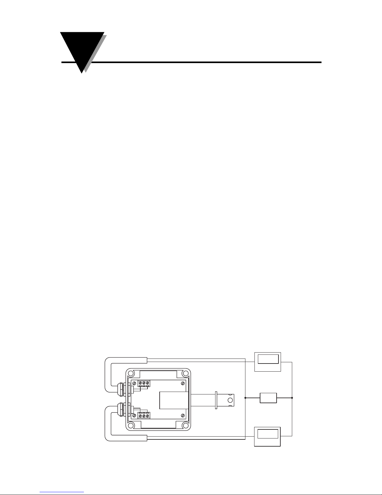
A 4-20 mA loop is a series loop in which a transmitter will vary the
current flow depending on the input to the transmitter. In the HX93A
and the HX93DA Series the amount of current allowed to flow in the
loop will vary depending on the relative humidity or temperature being
measured by the sensor(s). Some advantages of a current output over a
voltage output is that the signal measured is less susceptible to electrical
noise interference and the loop can support more than one measuring
instrument as long as the maximum loop resistance is not exceeded.
A typical application utilizing a current loop will normally consist of a
power supply, the transmitter and a meter, recorder or controller to
measure the current flow. The loop resistance in the sum of the
measuring instruments and wire used. The maximum allowable loop
resistance for the HX93A or HX93DA to function properly is found by
using the following formula:
For HX93A Rmax = (power supply voltage – 6 volts) ÷ .02 amps
EXAMPLE: (When using a 24 Vdc power supply).
Rmax = (24 – 6) ÷ .02 amps = 900 ohms max loop resistance
For HX93DA Rmax = (power supply voltage – 12 volts) ÷ .02 amps
EXAMPLE: (When using a 24 Vdc power supply).
Rmax = (24 – 12) ÷ .02 amps = 600 ohms max loop resistance
Figure 1 - Basic Transmitter Set-up With Current Loop Output
TB1
TB2
45%RH
24V
23°C
DPi8 Panel Meter
PSU-93
+
+
+–
–
–
DPi8 Panel Meter
3HX93A, HX93DA SERIES
RH/Temperature Transmitter
continued from page 1
3
Complimentary Instruments
Power Supply, OMEGA®Part No.: PSU-93
Csi32 Series Panel Meters and Controllers
Recommended Accessories
Shielded Transmitter Cable, OMEGA®Part No.: TX4-100 (100 ft)
RH Calibration Kit, OMEGA®Part No.: HX92-CAL
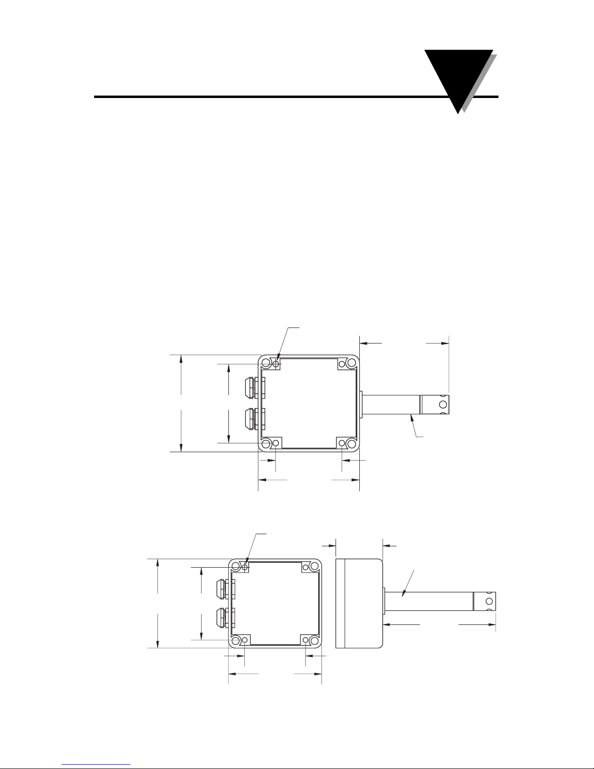
4. Mounting
OMEGA’s HX93A and HX93DA transmitter’s are designed for either
wall, duct or remote probe mounting depending upon model. Plastic
wall anchors and mounting screws are included for wall mounting and
remote probe models. A duct mounting kit is included with duct
mount models.
Figure 2 - Wall Mount Model Dimensions, mm (inches)
Figure 3 - Duct Mount & Remote Probe Model Dimensions, mm (inches)
DIMENSIONS mm (in.)
4.3 (.17)
MOUNTING
HOLE 63.5 (2.15)
ø15.8(ø.625)
49.8 (1.96)
79.8 (3.14)
95.3 (3.25) 69.9
4
HX93A, HX93DA SERIES
RH/Temperature Transmitter
DIMENSIONS mm (in.)
4.3 (.17)
MOUNTING
HOLE
95.3 (3.25) 69.9 (2.75)
79. (3.14)
49.8 (1.96)
55 (2.17)
16 (.62) DIA
127 (5.0)
4
5. Electrical Connections
All electrical connections and wiring should be performed by a suitably
trained professional only.
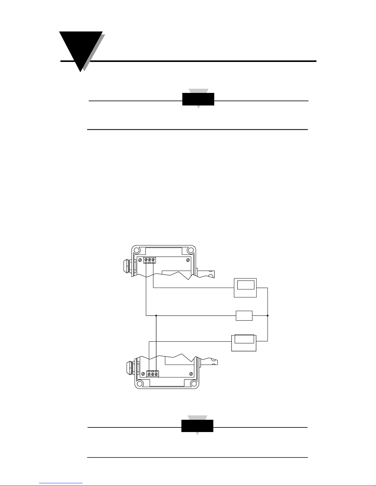
Models: HX93AC, HX93AC-D, HX93AC-RP1, HX93DAC, HX93DAC-
D,HX93DAC-RPI (Current Output)
TB1 - Relative Humidity TB2 - Temperature
1. + Power Supply 1. + Power Supply
2. No Connection 2. No Connection
3. 4-20 mA Output 3. 4-20 mA Output
6. Current Transmitter Wiring Examples
For current output models (4 – 20 mA)
Figure 4 - Current Transmitter Wiring Example, (4 - 20 mA)
All electrical connections and wiring should be performed by a suitably
trained professional only.
CAUTION
CAUTION
TB1
TEMPERATURE OUTPUT
RELATIVE HUMIDITY OUTPUT
DPi8 Panel Meter
45%RH
DPi8 Panel Meter
23°C
24V
PSU-93
21
TB2
3
1
32
+–
+
+–
–
5HX93A, HX93DA SERIES
RH/Temperature Transmitter
5
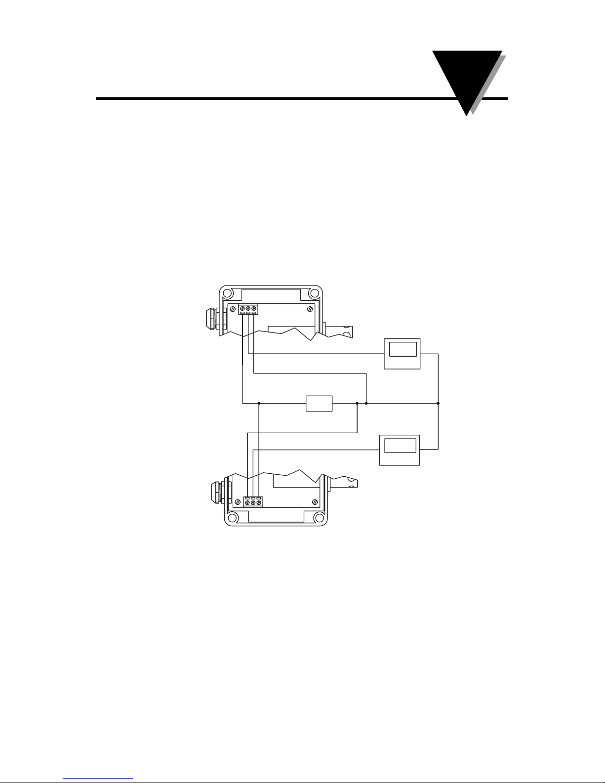
Models: HX93AV, HX93AV-D HX93AV-RP1 (Voltage Output)
TB1 - Relative Humidity TB2 - Temperature
1. + Power Supply 1. + Power Supply
2. + Output 2. + Output
3. - Power Supply 3. - Power Supply
7. Voltage Transmitter Wiring Examples
For voltage output models (0 to 1 Vdc)
Figure 5 - Voltage Transmitter Wiring Example
8. Relative Humidity Output Calculations
To calculate % Relative Humidity by measuring the current or voltage
output use the following formulas.
For current output:
% RH = (Current measured in miliamps – 4) ÷ .16
EXAMPLE: (11.04 mA – 4) ÷ .16 = 44% RH
For voltage output:
% RH = (Voltage measured in volts x 100)
EXAMPLE: .44 x 100 = 44% RH
2
31
2
13
RELATIVE HUMIDITY OUTPUT
TB1
TEMPERATURE OUTPUT
TB2
DPi8 Panel Meter
45%RH
PSU-93
DPi8 Panel Meter
24V
23°C
+
+
–
–
+–
7
HX93A, HX93DA SERIES
RH/Temperature Transmitter
6
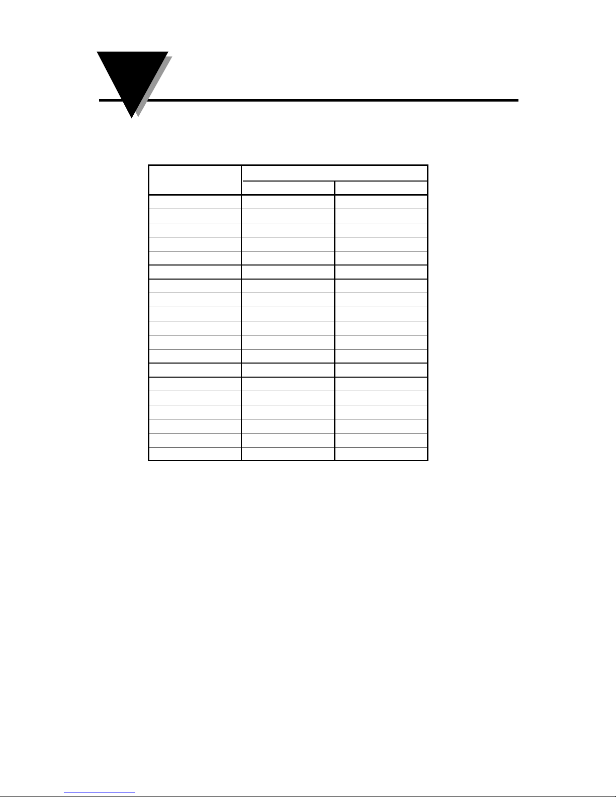
9. RH Measured Vs Output Reading
10. Temperature Output Calculations
To calculate Temperature by measuring the current or voltage output
use the following formulas.
For Current output in ºC (-20 to 75ºC)
ºC = (Output measured in miliamps – 4) ÷ .1684 - 20 = ºC
EXAMPLE: (12.0 mA – 4) ÷ .1684 - 20 = 27.5ºC
For Current output ºF (-4 to 167ºF)
ºF = (Output measured in miliamps – 4) ÷ .0935 - 4 = ºF
EXAMPLE: (12.0 mA – 4) ÷ .0935 - 4 = 81.6ºF
For Voltage output in ºC (-20 to 75ºC)
ºC = (Output measured in volts ÷ .010526) - 20 = ºC
EXAMPLE: (0.50 Vdc ÷ .010526) - 20 = 27.5ºC
For Voltage output ºF (-4 to 167ºF)
ºF = (Output measured in volts ÷ .005848) - 4 = ºF
EXAMPLE: (0.50 Vdc ÷ .005848) - 4 = 81.5ºF
% Relative Output
Humidity Current (mA) Voltage (Vdc)
5 4 0.8 .05
10 5.6 .10
15 6.4 .15
20 7.2 .20
25 8.0 .25
30 8.8 .30
35 9.6 .35
40 10.4 .40
45 11.2 .45
50 12.0 .50
55 12.8 .55
60 13.6 .60
65 14.4 .65
70 15.2 .70
75 16.0 .75
80 16.8 .80
85 17.6 .85
90 18.4 .90
95 19.2 .95
9HX93A, HX93DA SERIES
RH/Temperature Transmitter
Questo manuale è adatto per i seguenti modelli
3
Indice
Altri manuali Omega Engineering Trasmettitore

Omega Engineering
Omega Engineering ULTRASONIC LEVEL TRANSMITTER LVU-90 Manuale utente

Omega Engineering
Omega Engineering HX94 Manuale utente

Omega Engineering
Omega Engineering PHTX-11 Manuale utente

Omega Engineering
Omega Engineering HX92B Series Manuale utente

Omega Engineering
Omega Engineering TX801D RTD SERIES Manuale utente

Omega Engineering
Omega Engineering DPG1000L Manuale utente

Omega Engineering
Omega Engineering CYTX231 Series Manuale utente

Omega Engineering
Omega Engineering OS100E Series Manuale utente

Omega Engineering
Omega Engineering TX801TC SERIES Manuale utente

Omega Engineering
Omega Engineering TX801R Manuale utente


